
 Inggris
 中文简体
中文简体 Русский
 Español
 Português
 Türkçe
 العربية
 Deutsch
 Polski
 Italiano
 Français
 한국어
한국어 ไทย
ไทย Tiếng Việt
 日本語
日本語





























Ruang Uji Semprot Garam Komposit
Pengguna manual
berlaku LISUN Model: YWX/Q-010X,YWX/Q-016X,YWX/Q-020X,YWX/Q-250X
1. Membuka Kemasan dan Mengenal Peralatan
1.1 Spesifikasi Teknis Utama
|
LISUN Pilih Model |
YWX/Q-250X |
YWX/Q-750X |
YWX/Q-010X |
YWX/Q-016X |
YWX/Q-020X |
|
Dimensi Studio |
900 600 × × 500 |
1100 750 × × 500 |
1200 800 × × 500 |
1600 1000 × × 600 |
2000 1000 × × 600 |
|
Dimensi Kotak Luar |
2160 1100 × × 1300 |
2360 1250 × × 1300 |
2460 1300 × × 1350 |
2860 1500 × × 1450 |
3260 1500 × × 1450 |
|
Volume Laboratorium |
270L |
412L |
480 L |
960L |
1200 L |
|
Kapasitas Tangki Air Garam |
25 L |
30L |
30L |
35L |
40L |
|
Kapasitas Tangki Air Murni |
30L |
35L |
35L |
40L |
50L |
|
Sumber Daya listrik |
Arus bolak-balik tiga fasa 380 V/50 Hz (60 Hz tersedia berdasarkan permintaan) |
||||
|
10.0 kW |
12.0 kW |
12.5 kW |
16.0 kW |
18.5 kW |
|
|
Cara Membuka Tutupnya |
Manual Lid Opening |
Pegas Gas Baja Tahan Karat |
Silinder |
||
|
Kisaran Suhu Laboratorium |
15 ° C – 65 ° C |
||||
|
Saturated Drum Temperature Range |
RT (Room Temperature) ~ 70°C |
||||
|
Kelembaban relatif |
30%–98% RH (±3%, adjustable; see the “Temperature and Humidity Control Range” chart) |
||||
|
Tingkat Deposisi Semprotan Garam |
1–2 mL/80 cm²/h |
||||
|
Metode tes |
Programmable Spray, Damp Heat, Drying, Standard Climate |
||||
1.2 Membuka Kemasan dan Memeriksa Isinya
1.2.1 Membuka Kemasan dan Pemeriksaan Visual
When unpacking the equipment, handle it gently to avoid any impact on the main unit. After unpacking, first inspect the equipment casing, the glass door of the mist chamber, the touchscreen, and other components for any damage, deformation, or scratches.
Periksa semua sambungan peralatan (sambungan daya, saluran masuk udara, saluran keluar, saluran pembuangan, dll.) untuk memastikan semuanya dalam kondisi baik dan tidak longgar, tersumbat, atau rusak.
If you discover that the equipment or any accessories are damaged or deformed, do not power on the device; kontak LISUN Layanan pelanggan segera.
1.2.2 Tipe host
1 main unit of a Composite Salt Spray Test Chamber.
1 kompresor udara. Catatan: Ini dapat dibeli dari LISUN atau diperoleh secara independen. Jika diperoleh secara independen, lihat spesifikasi berikut: kapasitas tangki udara 55 L; laju aliran udara 0.6 m³/menit; tekanan maksimum: 0.8 MPa. Kompresor udara harus dilengkapi dengan pemisah minyak-air untuk mencegah minyak dan uap air dalam udara terkompresi masuk ke saluran udara peralatan, yang dapat menyebabkan penyumbatan nosel atau korosi komponen.
1.2.3 Bahan Habis Pakai dan Aksesoris
① Graduated cylinder; ② Sample holder, V-notch, and O-shaped rod; ③ Test salt: analytically pure sodium chloride, 500 g × 2; once used up, you may purchase more on your own or contact LISUN Customer Service; ④ Spare quartz glass nozzles.

Tautan unduhan untuk manual pengguna digital, kartu garansi, dan dokumen lainnya telah dikirimkan kepada Anda melalui email. Silakan unduh sesegera mungkin. Jika Anda melewatkan email tersebut, jangan ragu untuk menghubungi kami untuk meminta tautan unduhan lagi.
1.3 Deskripsi Struktur Peralatan
1.3.1 Tampilan Depan Ruang Uji
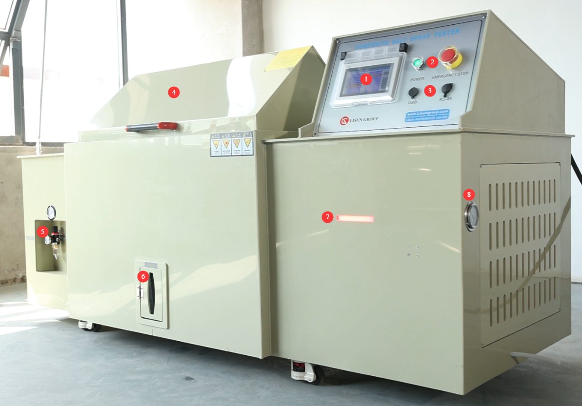
① Touchscreen; ② Power switch and emergency stop button; ③ USB port for exporting test curves; RS port (for backup); ④ Test chamber lid; ⑤ Air compressor connection and pressure regulator;⑥ Measuring cylinder, connected to the mist collector inside the test chamber; used when measuring rainfall. The number of funnels and measuring cylinders varies depending on the size of the test chamber; ⑦ Equipment status indicator light: red for alarms, yellow for standby, and green for operation; ⑧ Refrigerant pressure gauge.
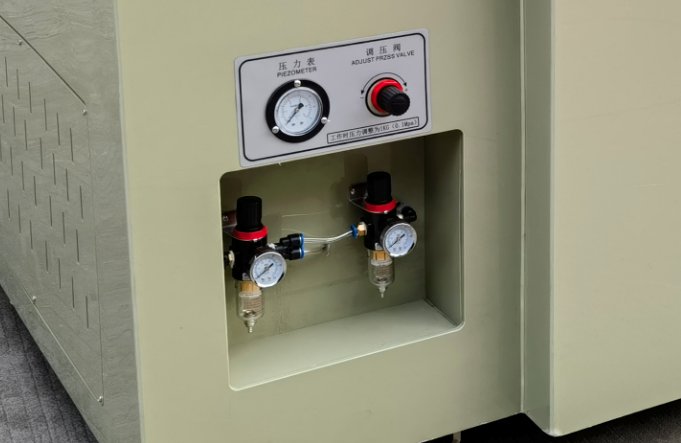
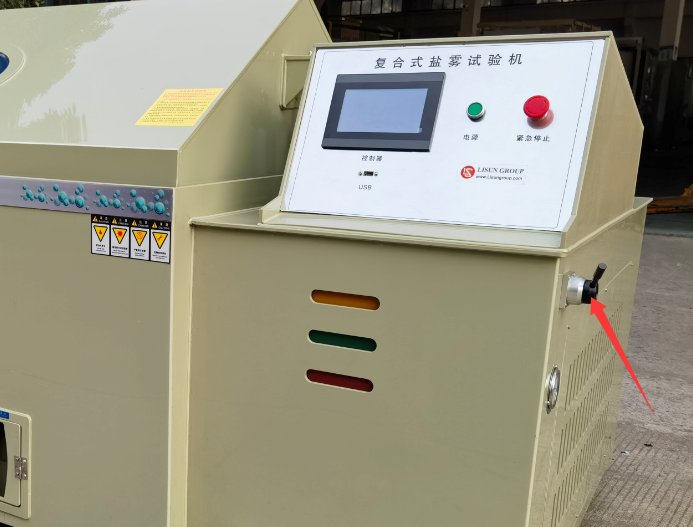
If your test chamber uses a pneumatic cylinder to open the lid, there will be an additional pressure regulator at the air compressor connection, and the unit will also have a handle for opening and closing the test chamber lid, as shown in the figure below:
1.3.2 Bagian Belakang Ruang Uji
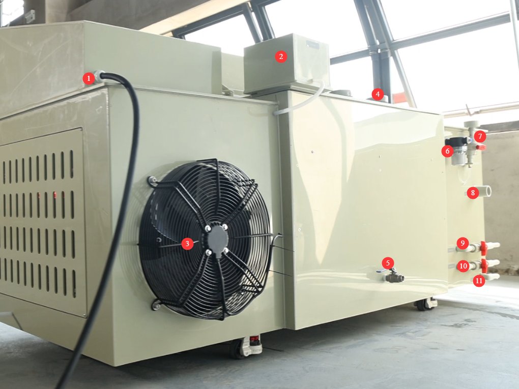
① Power cord; ② Gauze tray water tank; ③ Condenser exhaust fan; ④ Circulation fan (operates when controlling temperature and humidity); ⑤ Humidifier tray drain valve (remains closed during normal operation); ⑥ Pure water tank automatic refill port; ⑦ Saturation tank manual fill port;⑧ Mist exhaust port; ⑨ Brine tank drain pipe; ⑩ Pure water tank drain pipe; ⑪ Overflow port.
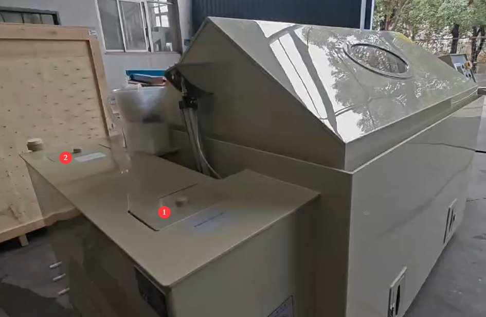
1.3.3 Side of the Test Chamber
① Brine tank; ② Pure water tank.
1.3.4 Di Dalam Ruang Uji (Ruang Kabut)
① Spray tower and nozzles; the number depends on the size of the test chamber; ② Brine level control device; ③ Temperature and humidity probes; brine hoses and saturated tank hoses—these hoses contain filters that need to be cleaned over time; ④ Mist collector; ⑤ Steam outlet for humidity testing;⑥ Fan outlet; ⑦ Air inlet for defogging—during defogging, compressed air from the air compressor enters the test chamber through this inlet; ⑧ Sealing water trough for the test chamber lid.
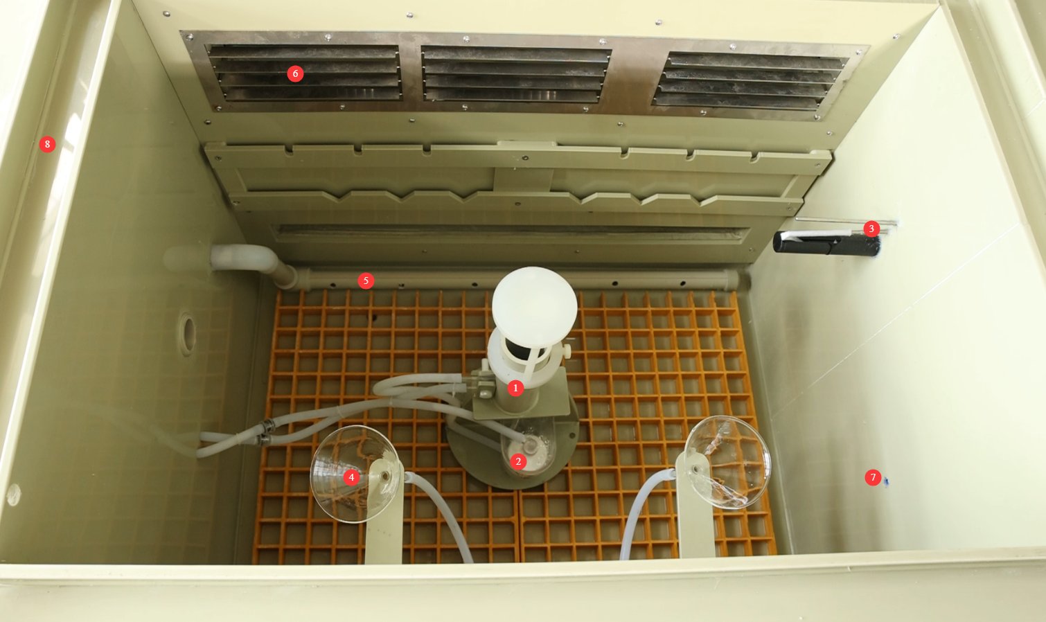
Note: If your test chamber uses a pneumatic cylinder to open the lid, you must turn on the power and the air compressor, and use the cylinder to open the lid before you can see inside the test chamber.
2. Tindakan Pencegahan Keamanan
2.1 Keamanan Listrik
2.1.1 Koneksi Daya
A 380V three-phase, five-wire power supply must be used, and the power rating must be matched to the specific model. The wire specifications for the corresponding equipment models must meet the following requirements: YWX/Q-250X ≥ 2.5 mm²; YWX/Q-750X, YWX/Q-010X ke YWX/Q-016X ≥ 4.0 mm²; YWX/Q-020X ≥ 6.0 mm². A dedicated circuit must be used for power supply, and it is recommended to install a separate circuit breaker.
2.1.2 Spesifikasi Pembumian
Grounding must be performed in accordance with the standards for three-level grounding systems, with a grounding resistance of ≤50 Ω; a dedicated grounding wire must be used to connect to the ground.
It is strictly prohibited to connect grounding wires to gas lines, non-metallic water pipes, heating pipes, or other flammable or explosive facilities to avoid the risk of electric shock or fire.
2.1.3 Kontraindikasi untuk Prosedur
Before connecting, servicing, or replacing parts on the equipment, you must disconnect the power supply before proceeding.
Jangan menyentuh konektor daya, layar sentuh, atau komponen listrik lainnya dengan tangan basah. Jaga agar area di sekitar perangkat terbebas dari genangan air untuk mencegah sengatan listrik.
If any abnormalities occur while the equipment is in operation—such as electrical leakage, unusual noises, or smoke—immediately disconnect the power supply and contact a professional for repair; do not attempt to disassemble the equipment yourself.
2.2 Keselamatan Operasional
2.2.1 Test Specimen Restrictions
This device is intended only for testing non-flammable, non-explosive, and non-radioactive solid or flexible materials (such as metal coatings, plastic parts, electronic component housings, etc.).
If the sample contains volatile components (such as organic solvents or corrosive gases), you must consult the equipment compatibility instructions in advance or conduct a preliminary test with a small sample to confirm that there are no safety risks (such as corrosion of equipment components or the generation of toxic gases). Otherwise, do not place the sample in the equipment.
2.2.2 Menghubungkan Pipa Knalpot dengan Benar
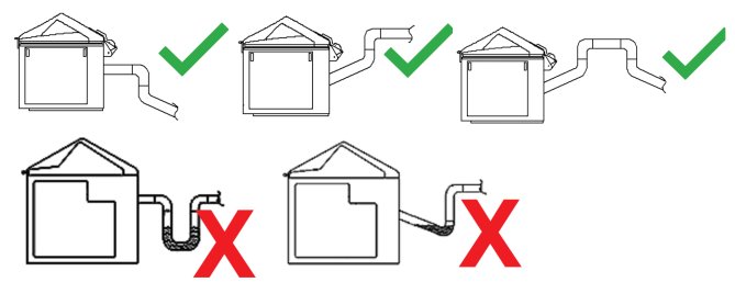
Salt fog is corrosive; the exhaust pipe must be connected to the outdoors or a dedicated drainage system. It must not be discharged indoors or connected to a standard sewer system.
The mist exhaust pipe must remain unobstructed, free of kinks or blockages, and must not include a P-trap; otherwise, salt spray condensate will accumulate inside the pipe, blocking the exhaust channel and affecting test results and equipment safety. See the diagram below:
2.2.3 Perilaku yang Dilarang
While the equipment is in operation, non-professionals are prohibited from disassembling or repairing it. In the event of a malfunction, contact customer service or follow the instructions of a technician.
If the equipment triggers an alarm, immediately stop the test and troubleshoot the problem (see “Chapter 6: Troubleshooting and Resolution of Common Problems”). Do not force the equipment to restart; operating it before the problem is resolved may cause further damage to the equipment.
Do not open the test chamber lid until the test is complete and the defogging process has finished, to prevent direct contact between the salt spray and human skin.
Do not disassemble core components such as nozzles, temperature probes, heating elements, and liquid level sensors without authorization. Do not modify the equipment’s electrical, pneumatic, or structural systems. Failure to comply will void the equipment’s warranty and may result in safety incidents.
2.3 Keselamatan Lingkungan
2.3.1 Persyaratan Instalasi
Suhu lingkungan: 5–25°C. Hindari suhu yang terlalu tinggi, karena dapat memengaruhi stabilitas kontrol suhu ruang uji, dan suhu yang terlalu rendah, karena dapat memengaruhi efisiensi pemanasan.
Kelembaban relatif: ≤85% RH. Lingkungan harus kering untuk mencegah korsleting pada komponen listrik peralatan yang disebabkan oleh kelembapan.
Persyaratan Lain: Tidak ada sinar matahari langsung (untuk mencegah fluktuasi suhu di ruang semprot garam); tidak ada medan elektromagnetik yang kuat (seperti yang berasal dari transformator tegangan atau motor listrik besar, untuk menghindari gangguan pada sistem kontrol); tidak ada arus udara yang kuat (seperti aliran udara langsung dari ventilasi pendingin udara, yang dapat memengaruhi distribusi semprotan garam); kisaran tekanan atmosfer: 86–106 kPa.
2.3.2 Persyaratan Ruang
The equipment must be placed on a level surface; use a level to ensure the unit is stable (tilting may cause uneven salt spray distribution and liquid leaks).
Allow sufficient space around the equipment: ≥1500 mm on the left, right, and rear sides (to facilitate piping and cable connections, liquid refills, and maintenance), and ≥2000 mm at the front (to allow access to the control panel door and touchscreen).
2.4 Lainnya
Untuk hal-hal yang tidak tercakup dalam panduan ini, harap berhati-hati atau hubungi kami.
3. Persiapan Sebelum Operasi
3.1 Sambungan Saluran Kabel
3.1.1 Koneksi Kabel Daya
Lihat 2.1.
3.1.2 Sambungan Pipa Knalpot
Gunakan selang pembuangan yang disediakan oleh LISUN. If you provide your own exhaust hose, please use a hose with an inner diameter of 50 mm and connect it as described in Section 2.2.2.
3.1.3 Sambungan Pipa Pembuangan
For the brine tank water supply line, the purified water tank drain line, and the overflow outlet, use non-metallic tubing (such as PPR tubing) with an inner diameter of 20 mm. Connect one end to the drain port on the back of the unit and the other end to the sewer line. The tubing must be installed at a slope to ensure proper drainage.
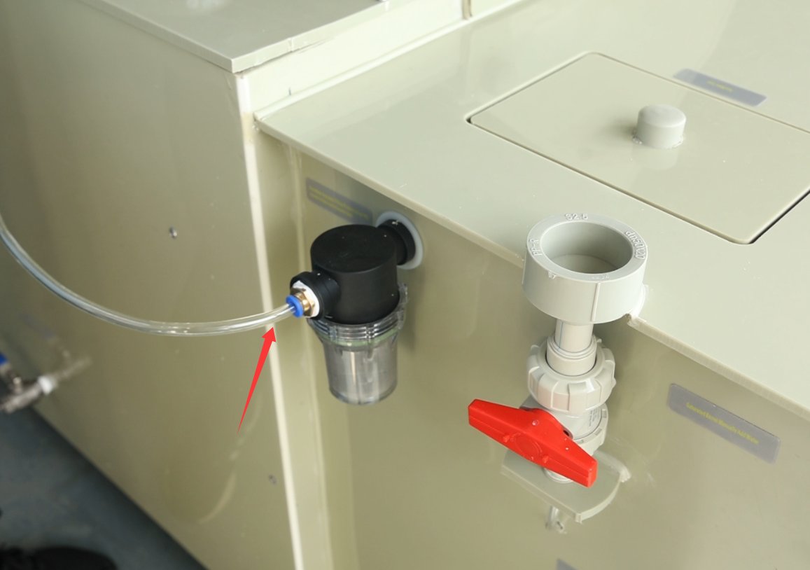
3.1.4 Connection of the Automatic Water-Filling Port on the Pure Water Tank
Connect to a purified water source under pressure using an 8mm-diameter water tube (water quality must be pH 6.5–7.5; do not use tap water or bottled water to prevent scale buildup), The inlet pressure must be ≥0.1 MPa. Keep the valve open at all times to automatically fill the purified water tank, which will then automatically replenish the humidifier chamber and the saturation tank.
3.1.5 Sambungan Kompresor Udara dan Penyesuaian Tekanan Masuk
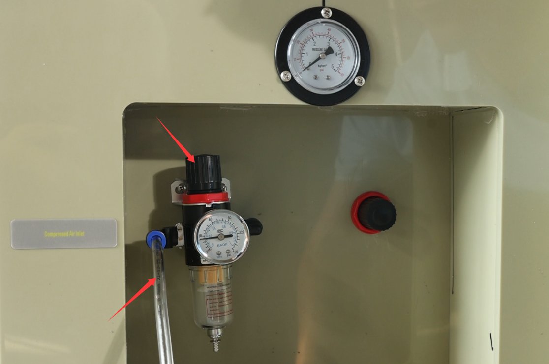
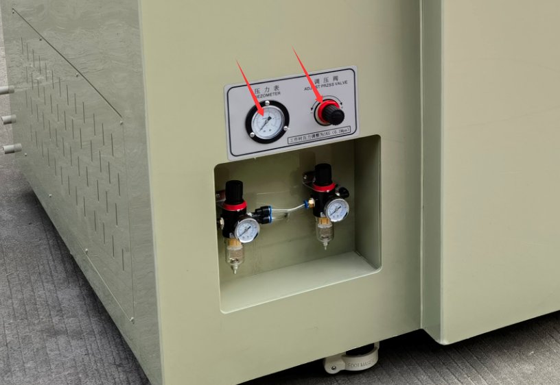
Gunakan selang udara berdiameter 8 mm, sambungkan salah satu ujungnya ke saluran keluar kompresor udara dan ujung lainnya ke saluran masuk udara di bagian belakang perangkat. Atur kenop yang ditunjukkan pada gambar di bawah untuk mengatur tekanan udara ke 0.2 MPa untuk penyemprotan.
Jika ruang semprot garam Anda menggunakan silinder pneumatik untuk membuka tutupnya, akan ada dua regulator tekanan, seperti yang ditunjukkan pada gambar di bawah ini: ① Yang pertama memasok udara ke silinder dan harus diatur ke 0.4 MPa. ② Yang kedua untuk semprotan dan harus diatur ke 0.2 MPa.
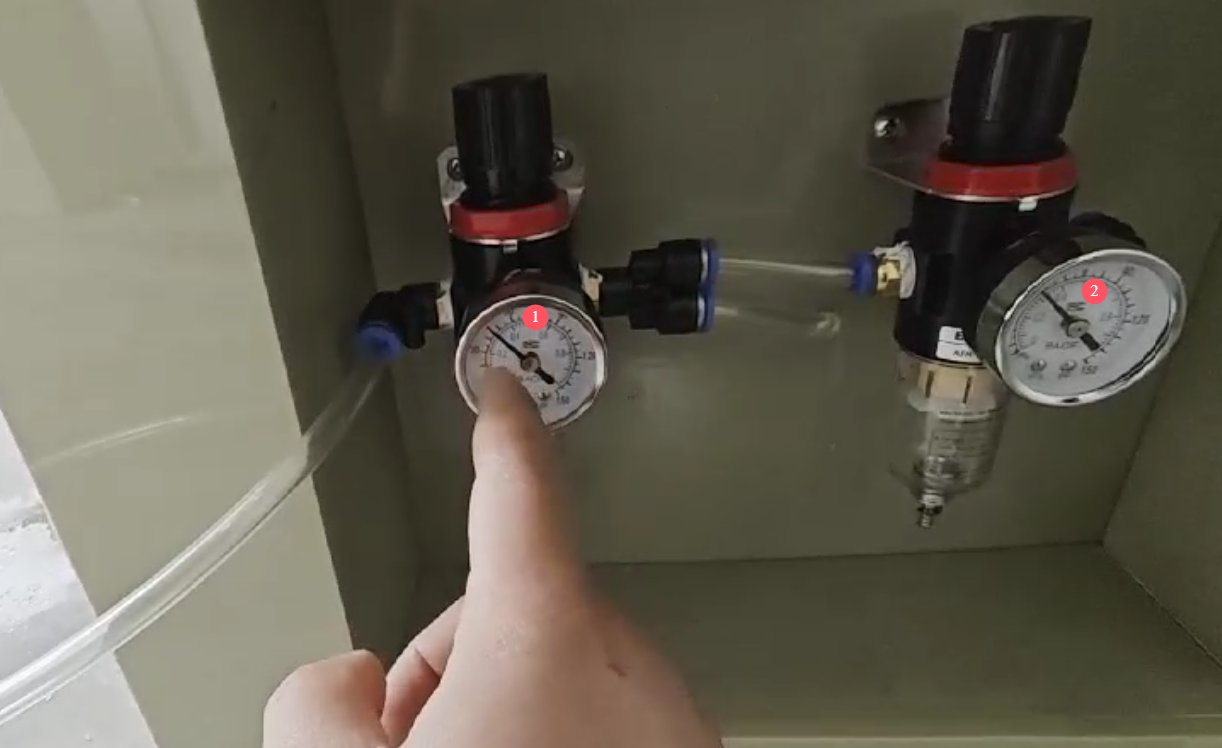
Setelah melakukan penyesuaian, pantau sistem dan pastikan tekanan udara tetap stabil; tekanan udara yang tidak stabil dapat memengaruhi kinerja penyemprotan.
3.2 Checking the Status of the Test Chamber
3.2.1 Membersihkan Ruang Uji
During transportation, it is inevitable that debris or dust will enter the test chamber. Before using the equipment for the first time, please clean the interior of the test chamber, the saltwater tank, the pure water tank, the gauze tray water tank, and other components with clean water. Once everything has been thoroughly cleaned and the cleaning water has been drained, ensure that all drain valves on the equipment are closed.
3.2.2 Starting Up the Test Chamber
When the test chamber is first turned on, a low-water alarm may sound; the alarm will clear once the water reservoir is fully refilled.
3.3 Menambahkan Air
3.3.1 Manual Water Filling of the Saturation Tank
Open the red valve at the manual fill port on the saturated tank and pour in purified water directly (do not use tap water or bottled water to prevent limescale buildup) until the tank is full.
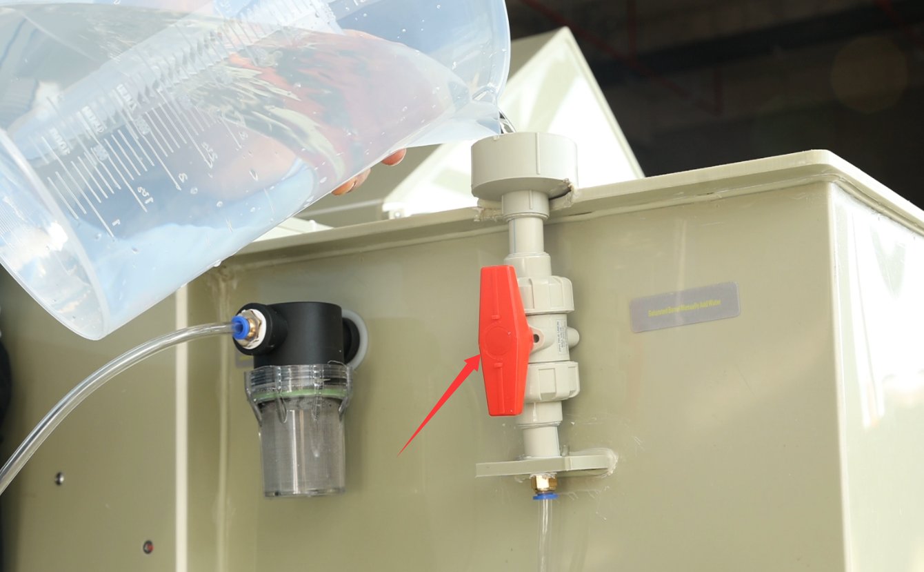
Setelah menambahkan air secara manual, pastikan untuk menutup katup; jika tidak, air bertekanan tinggi akan menyembur keluar selama pengujian.
If water is not added manually, the system will automatically replenish water from the purified water tank when the saturation tank runs low after the unit is turned on or during testing.
3.3.2 Filling the Gauze Trough Water Tank
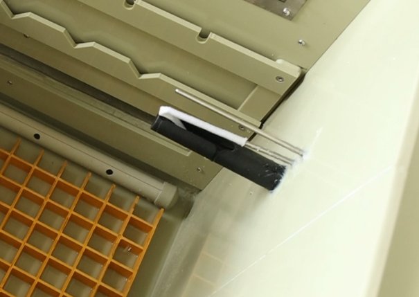
Add an adequate amount of pure water. This is used to moisten the gauze on the humidity probe and requires very little water. During long-term continuous testing, it is generally not necessary to refill the water. If the water level is low, the program will sound an alarm.
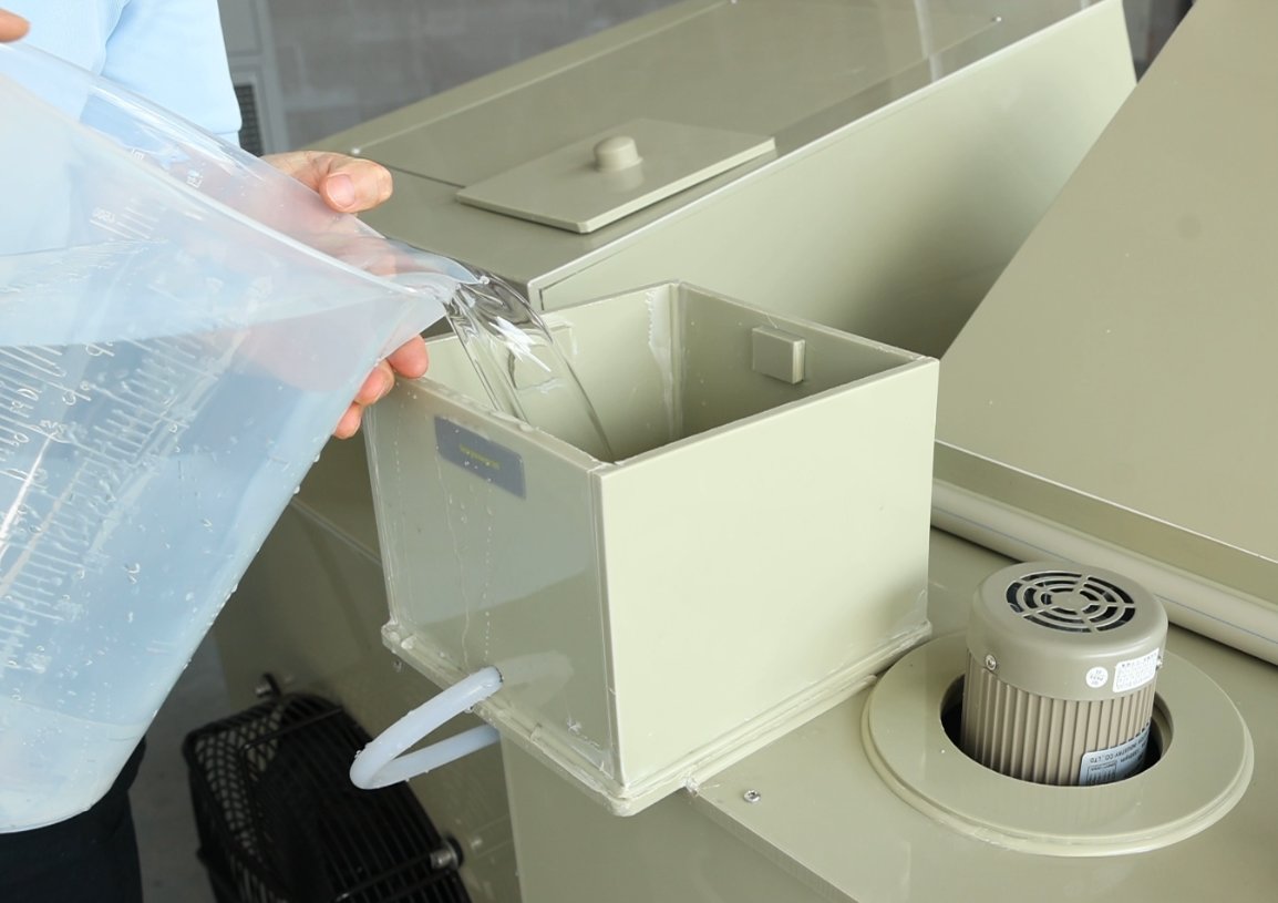
After adding water, it will automatically flow into the gauze reservoir of the humidity probe inside the test chamber. One end of the gauze—at least 50 mm long—should be slipped over the humidity probe, while the other end should be submerged in the reservoir. Ensure that the entire length of the gauze is thoroughly moistened.
3.3.3 Mengisi Palung Penyegelan dengan Air
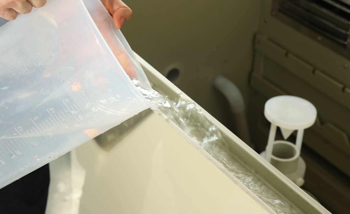
A sealing water trough is installed around the perimeter of the test chamber lid. Fill the trough with clean water until the water level is 2–3 cm above the bottom of the trough to ensure that the test chamber remains airtight after the lid is closed, preventing salt spray from leaking through gaps in the lid during the test.
3.4 Persiapan dan Injeksi Larutan Garam
3.4.1 Selection and Preparation of Saltwater Concentration
Sesuai dengan persyaratan standar pengujian, pilih jenis semprotan garam yang sesuai dan siapkan larutannya. Jenis-jenis umum adalah sebagai berikut:
|
Jenis-jenis Semprotan Garam |
Standar yang berlaku |
Metode Persiapan |
Penting Catatan |
|
Uji Semprot Garam Netral (NSS) |
GB/T 10125, ISO 9227 |
500 g analytically pure sodium chloride + 9500 mL purified water; stir until the sodium chloride is completely dissolved, resulting in a 5% solution |
Sodium chloride must be completely dissolved, with no precipitate; purified water must meet the Grade 1 standards specified in GB/T 6682. |
|
Semprotan Garam Asam (AASS) |
GB/T 10125, ISO 9227 |
Tambahkan asam asetat glasial secara perlahan ke dalam larutan NSS, dan gunakan pH meter (atau kertas pH dengan akurasi 0.1) untuk menyesuaikan pH hingga 3.0–3.1. |
Glacial acetic acid is corrosive; wear gloves and safety goggles, and add it slowly in drops to avoid splashing. |
|
Uji Semprot Garam yang Dipercepat Tembaga (CASS) |
GB/T 10125, ISO 9227 |
Tambahkan 0.26 g/L tembaga(II) klorida anhidrat ke dalam larutan NSS; aduk hingga larut, kemudian panaskan hingga sekitar 50°C untuk menghilangkan karbon dioksida dari larutan; setelah dingin, sesuaikan pH hingga 3.0–3.1. |
Tembaga klorida harus ditimbang dengan akurat; saat memanaskan, berhati-hatilah agar larutan tidak meluap. |
3.4.2 Injeksi Air Garam
Open the fill port on the brine tank and slowly pour the prepared brine into the tank, taking care to prevent the solution from splashing and corroding the equipment surface.
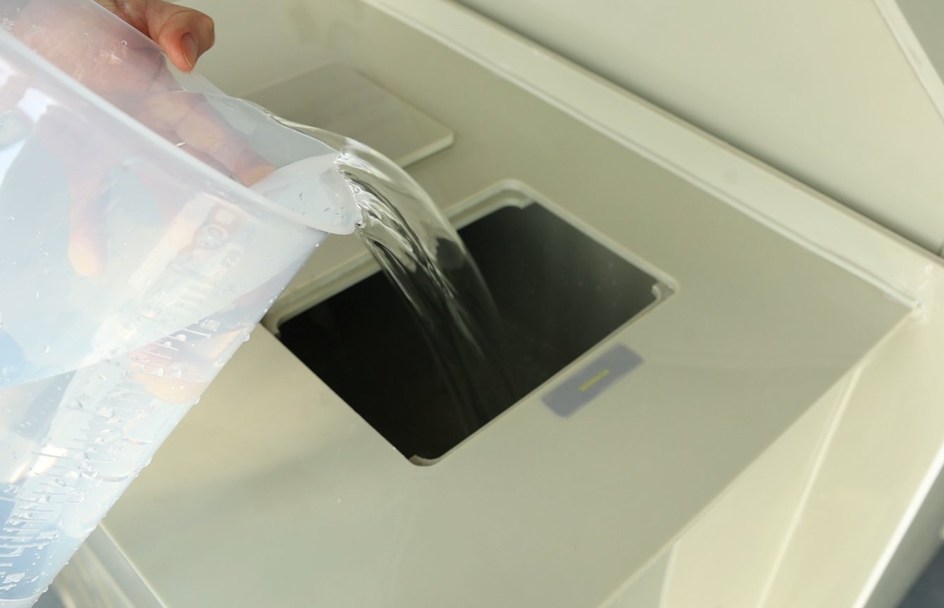
Observe the touchscreen; when the low-salt-water indicator on the salt water tank disappears, it means the salt water has reached the minimum operating level. However, if a long-term test is required (e.g., exceeding 24 hours), you may continue to fill the salt water tank until it is full (without exceeding the overflow port) to reduce the number of times you need to refill the salt water during the test. Approximately 12 liters of brine is sufficient to power one spray tower for 24 hours of continuous spraying.
3.5 Persiapan dan Pemuatan Sampel
3.5.1 Pembersihan Sampel
Before testing, clean the sample surface to remove contaminants such as oil, dust, and fingerprints: Gently wipe the surface with a lint-free cotton swab dipped in anhydrous ethanol, or rinse with purified water and allow it to air dry. Avoid excessive wiping, which could damage the sample’s surface coating (such as electroplated or painted layers).
If there is any temporary protective coating on the sample surface (such as a protective film or rust-preventive paper), it must be completely removed to ensure that the sample surface comes into full contact with the salt spray.
3.5.2 Perlindungan Tepi
If the sample has cut edges, drilled holes, or marked areas (non-test areas), they must be sealed with heat-resistant, salt-spray-resistant paint or tape to prevent galvanic corrosion in these areas, which could affect the accuracy of the test results.
Harus dipastikan terlebih dahulu bahwa bahan penyegel tidak bereaksi dengan larutan semprot garam dan tidak akan mencemari area pengujian sampel.
3.5.3 Pemilihan Pemegang dan Penempatan Sampel
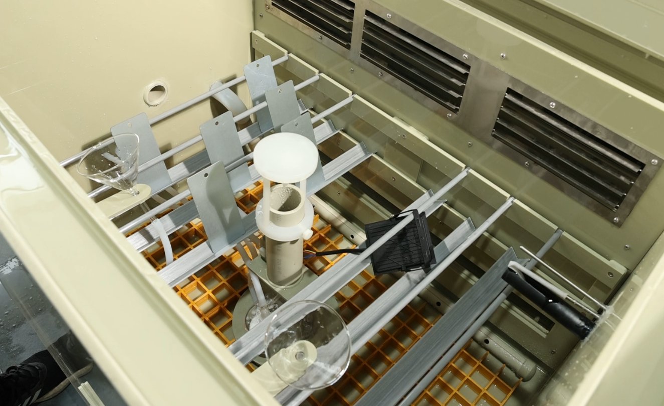
Choosing a Holder: Select a holder based on the sample’s size and shape—small samples can be suspended using round or triangular holders, while large or flat samples can be placed directly on the yellow mesh divider at the bottom of the mist chamber.
Persyaratan Tampilan:
Spesimen pelat logam standar harus ditempatkan pada sudut 15–25° (sudut dapat disesuaikan menggunakan penyangga) sehingga permukaan uji spesimen sejajar dengan arah aliran semprotan garam, memastikan cakupan yang seragam oleh semprotan garam;
Sufficient spacing must be maintained between samples (at least 1.5 times the largest dimension of the sample) to prevent the samples from coming into contact with one another or obstructing the salt spray, and salt spray condensation from one sample must not drip onto another sample;
The total volume of the sample must not exceed 3/5 of the chamber volume to avoid disrupting air circulation within the chamber, which could result in uneven temperature and salt spray distribution.
Kecuali sekat dan tempat sampel, sampel tidak bersentuhan dengan komponen lain di dalam ruang uji.
3.6 Penyesuaian Tekanan Semprotan
For instructions on using the touchscreen, please refer to Chapter 4.
Close the test chamber lid. Go to the “Operation Settings” screen on the touchscreen, select “FIX” mode, and disable the “Fixed Value Standby” function. Go to the “Monitoring Screen,” select only “Salt Spray” as the operating mode, start the test, and begin spraying immediately.
Adjust the pressure regulating valve shown in the figure below so that the spray pressure gauge reads 1 kg/cm² (0.1 MPa). Observe the spray pattern from the nozzles inside the spray chamber: the spray should form a fine, uniform mist with no water droplets or interruptions, and the spray range of the spray tower (if present) should cover the entire spray chamber.
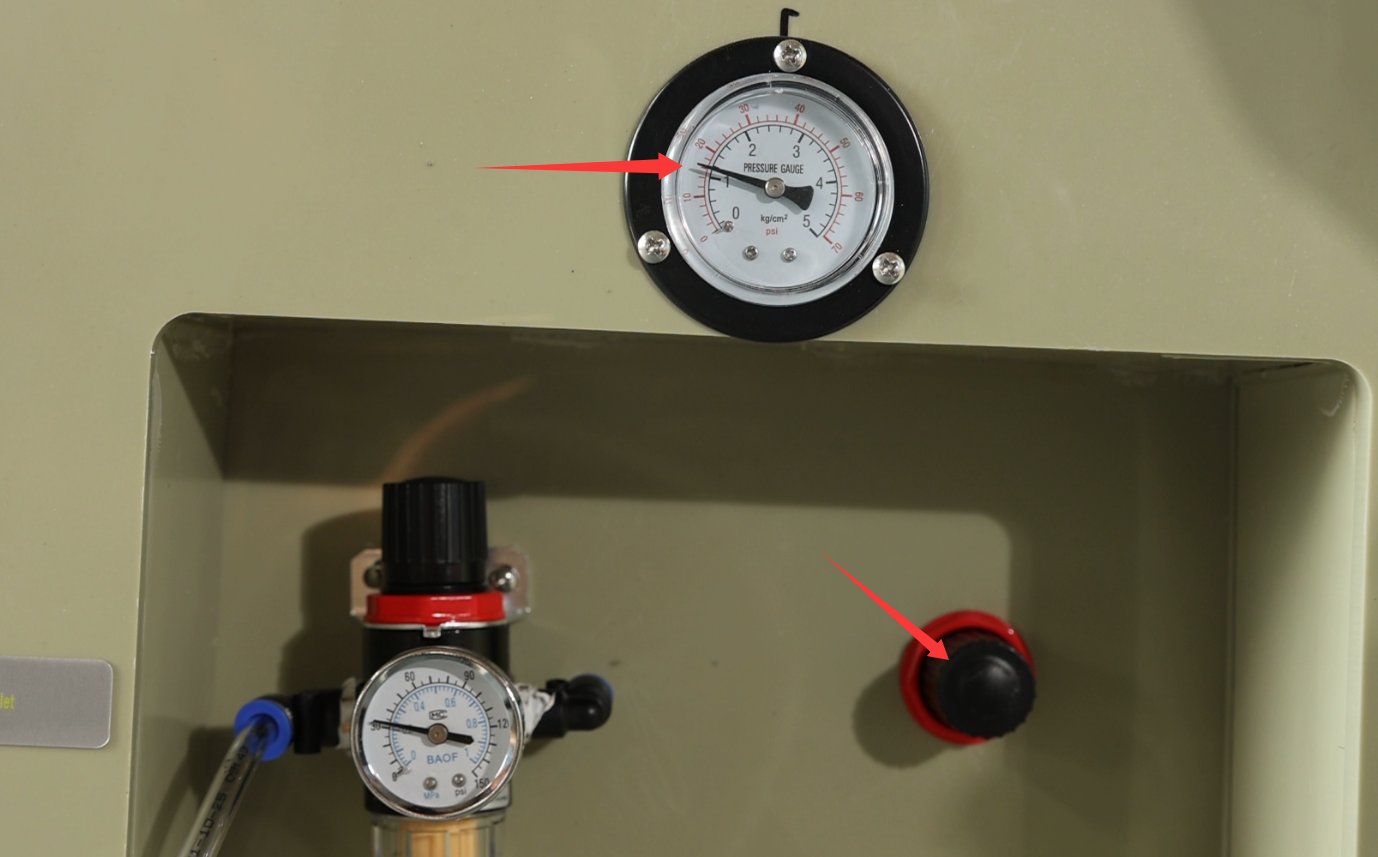
If your test chamber uses a pneumatic cylinder to open the lid, the spray pressure regulator and spray pressure gauge are located as follows:
After pre-spraying for 5 to 10 minutes, verify that the spray is uniform, with no water droplets and no interruptions in the spray pattern.
4. Prosedur Pengujian (Operasi Layar Sentuh Utama)
Touchscreen Main Menu Screen:
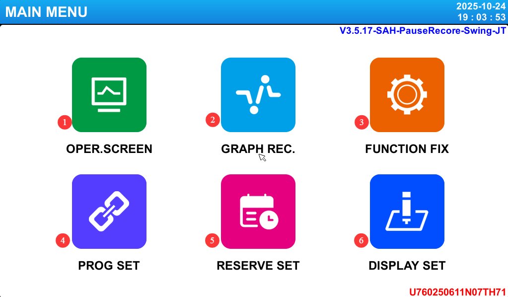
|
Project |
Nama |
Note |
|
① |
Rekaman Pengawasan |
Displays real-time operating data, fault information, and more. |
|
② |
Tampilan Melengkung |
View test curves; data backup is supported. |
|
③ |
Pengaturan Operasi |
Select test mode (fixed value/program), power-off mode, etc. |
|
④ |
Pengaturan Program |
Edit a multi-segment test program. |
|
⑤ |
Pengaturan Janji Temu |
Set the scheduled start time and the current time. |
|
⑥ |
Tampilan Pengaturan |
Change the language, adjust the screen backlight timeout, and more. |
4.1 Introduction to the Operation Settings Screen
Buka layar “Pengaturan Operasi”:
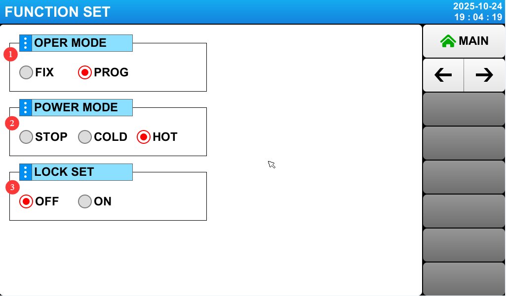
|
Project |
Nama |
Note |
|
① |
Operasi Mode |
Select either the FIX test or the PROG test. |
|
② |
Power-Off Mode |
Configure power-up operations in the event of a power outage. ☞ Stop: The operation that restores the system to the “Stop” state when power is restored after a power outage during operation . ☞ Cold Start: The operation that restarts the system when power is restored after a power outage during operation. ☞ Hot Start: The operation that restores the system to its pre-outage state when power is restored after a power outage during operation. |
|
③ |
Mengunci |
When the lock is set to “On,” none of the PARAMETER settings can be used. |
Go to page 2 of the “Operation Settings” screen:
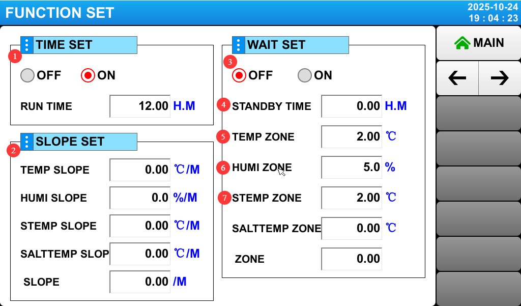
|
Project |
Nama |
Note |
|
① |
Fixed-Value, Fixed-Time Operasi |
Set the runtime; this applies only when operating at a fixed value. If set to 0, you’ll need to click “Stop” manually. |
|
② |
Fixed Slope |
Unless otherwise specified, do not modify this setting; simply use the default value of 0, and the device will operate at an automatic slope. Setting any other value may cause the device to malfunction. |
|
③ |
Fixed-Value Wait Pengaturan |
Standby Function and Standby Parameter Settings. If this function is enabled, the test timer will not start until the device reaches the target value (for salt spray tests, spraying will not begin until the target temperature is reached). ☞ Example: Set the temperature to 60°C, select “On” for Standby, set the temperature range to 1.00, and set the standby time to 1.00. Timing begins when the measured temperature reaches 60±1°C. If the target value is not reached within 1 hour, the test timer will automatically start. |
|
④ |
Waktu menunggu |
Set the maximum duration for “fixed-value wait.” |
|
⑤ |
Temperature Zones in the Test Chamber |
If the setting is 2—that is, when the actual temperature differs from the target temperature by 2°C—the target temperature is considered to have been reached. |
|
⑥ |
Humidity Zone of the Test Chamber |
If the setting is 5—meaning that when the actual humidity differs from the target humidity by 5%—the target humidity is considered to have been reached. |
|
⑦ |
Saturated Zone Temperature Range |
If the setting is 2—that is, when the actual temperature differs from the target temperature by 2°C—the target temperature is considered to have been reached. |
4.2 Introduction to the Appointment Settings Screen
Buka layar “Pengaturan Penjadwalan”:
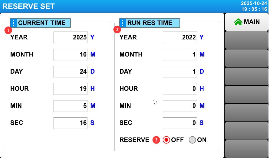
|
Project |
Nama |
Note |
|
① |
Waktu saat ini |
Displays or sets the current time. |
|
② |
Waktu perjanjian |
You can set an appointment time. |
|
③ |
Pengaturan Janji Temu |
If the scheduling setting is enabled, the device will automatically run the selected test at the scheduled time. |
4.3 Introduction to Display Settings
Go to “Display Settings”:
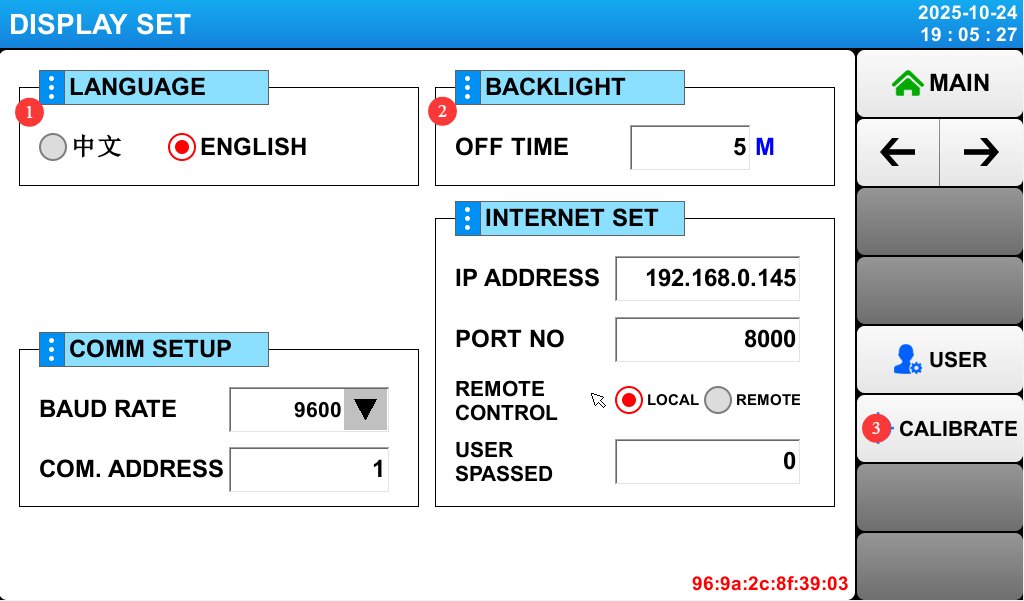
|
Project |
Nama |
Note |
|
① |
Beralih Bahasa |
You can switch the display language between Chinese and English. |
|
② |
Backlight Duration |
You can set the touchscreen backlight timeout. |
|
③ |
Kalibrasi Sentuh |
If the touchscreen is not responding accurately, enter Calibration mode. Contact LISUN Customer Service for assistance. |
4.4 Uji Kalibrasi (FIX)
4.4.1 Pendahuluan tentang Layar Uji Kalibrasi
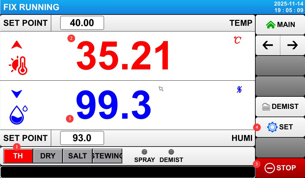
Go to the “Operation Settings” screen, select “FIX” for “Operation Mode,” and then go to the “Monitoring Screen.”
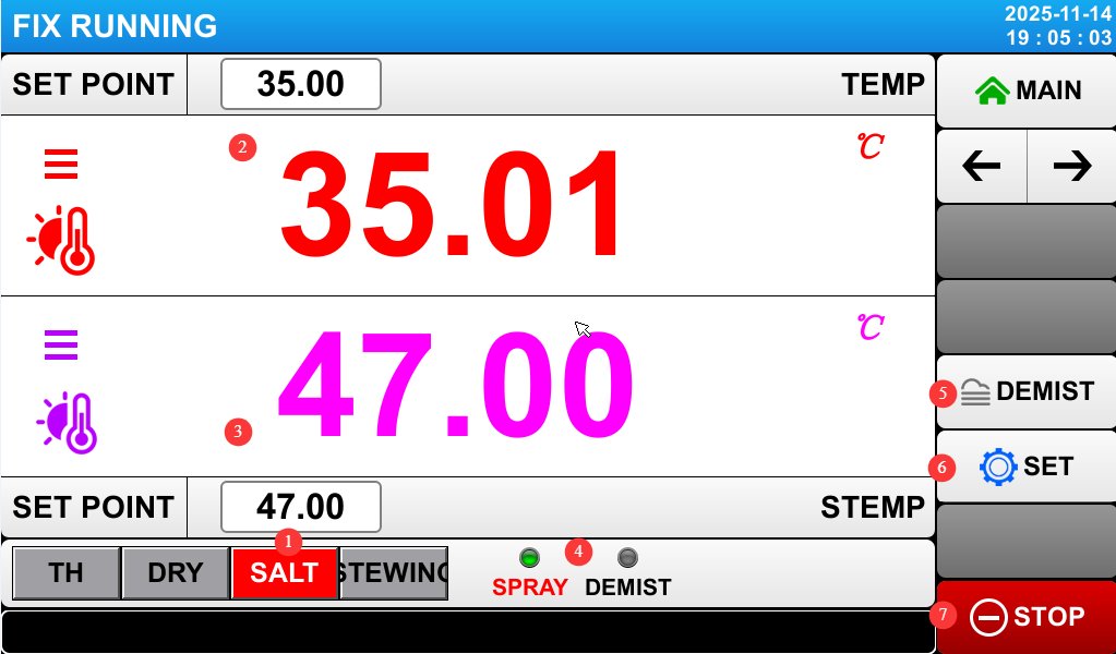
|
Project |
Nama |
Note |
|
① |
Selecting a Salt Spray Test |
In the salt spray test interface, temperature, humidity, and drying tests cannot be performed. |
|
② |
Temperature of the Test Chamber (Fog Chamber) |
Displays the current test chamber temperature; you can set the desired test chamber temperature. The default setting is 35°C (the standard temperature for NSS/AASS testing). If you need a different temperature, you can enter it using the touchpad (the range is typically 10–60°C). |
|
③ |
Saturated Drum Temperature |
Displays the current saturation temperature; you can set the desired saturation temperature value. The default setting is 47°C (to ensure saturated air humidity and prevent spray cooling), which should be 10–15°C higher than the test chamber temperature. |
|
④ |
Spray and Demist Modes |
Menampilkan status penyemprotan dan penghilang kabut saat ini. |
|
⑤ |
Manual Defogging |
Press this button to activate the defogging function; compressed air will enter the test chamber to quickly remove fog. |
|
⑥ |
Fixed-Value Test Settings |
Click to open the fixed-value test settings screen. |
|
⑦ |
Jalankan tombol |
Click to start or stop the current test. |
|
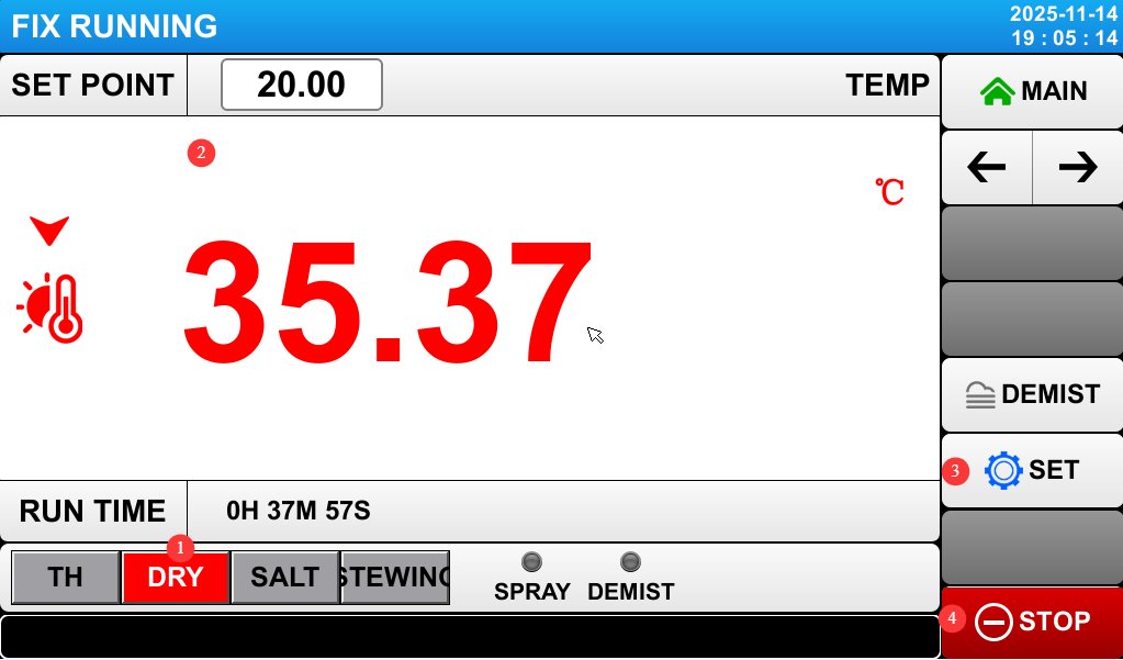
Project |
Nama |
Note |
|
① |
Select Temperature and Humidity Testing |
Salt spray and drying tests cannot be performed in the temperature and humidity test interface. |
|
② |
Suhu Ruang Uji |
Displays the current temperature of the test chamber; you can set the desired temperature for the test chamber. |
|
③ |
Kelembaban Ruang Uji |
Displays the current humidity level in the test chamber; you can set the desired humidity level for the test chamber. |
|
④ |
Fixed-Value Test Settings |
Click to open the fixed-value test settings screen. |
|
⑤ |
Tombol Jalankan |
Click to start or stop the current test. |
|
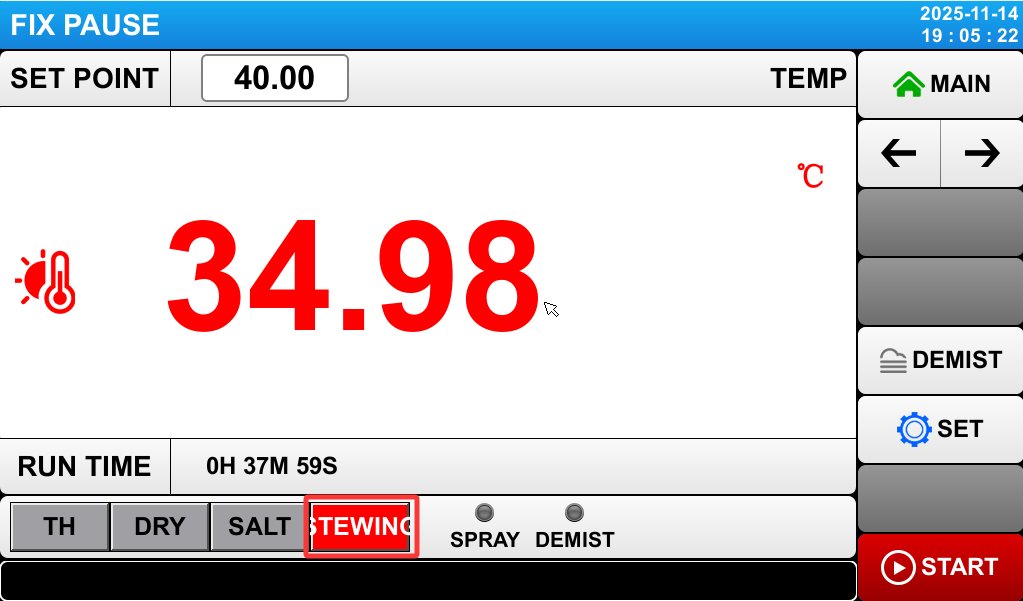
Proyek |
Nama |
Note |
|
① |
Select Drying Test |
In the drying test interface, salt spray and temperature/humidity tests cannot be performed. |
|
② |
Suhu Ruang Uji |
Displays the current temperature of the test chamber; you can set the desired temperature for the test chamber. |
|
③ |
Fixed-Value Test Settings |
Click to open the fixed-value test settings screen. |
|
⑤ |
Jalankan tombol |
Click to start or stop the current test. |
If you select the “static” test, the test chamber will remain completely still; once the test begins, the samples remain stationary inside the test chamber.
4.4.2 Introduction to the Fixed-Value Test Settings Screen
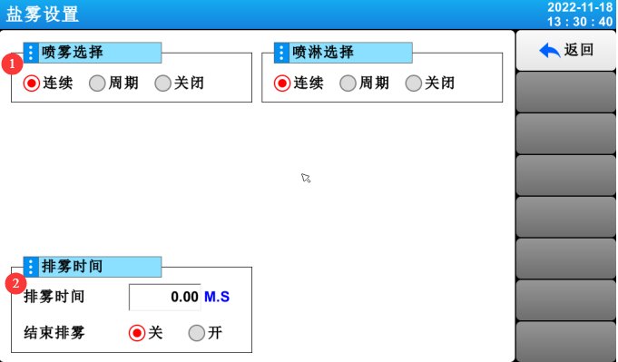
On the “Monitoring Screen” of the calibration test, click “Settings” to open the parameter settings screen:
|
Project |
Nama |
Note |
|
① |
Opsi Semprotan |
Continuous, Cyclic, Off. |
|
② |
Defogging Time |
Enable the “End Defogging” function and enter the defogging time; the system will then automatically perform defogging once the salt spray test is complete. If the “End Defogging” function is enabled, manual defogging is no longer required. |
4.5 Program Testing (Multi-Mode Automatic Switching)
Go to the “Operation Settings” screen, select “Program (PROG)” under “Operation Mode,” and then go to the “Program Settings” screen:
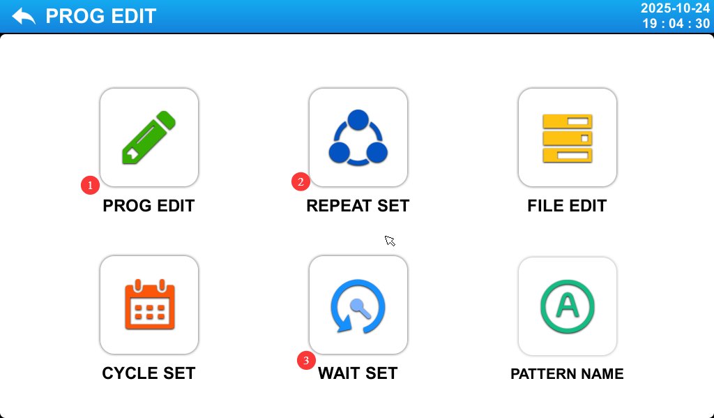
|
Project |
Nama |
Note |
|
① |
Pengeditan Program |
Edit the program number, name, test segment number, and other parameters. |
|
② |
Pengaturan Perulangan |
Loop testing mode for editing programs. |
|
③ |
Standby Settings |
Wait Function and Wait Parameter Settings. |
4.5.1 Introduction to the Program Editor Screen
Buka layar “Editor Program”:
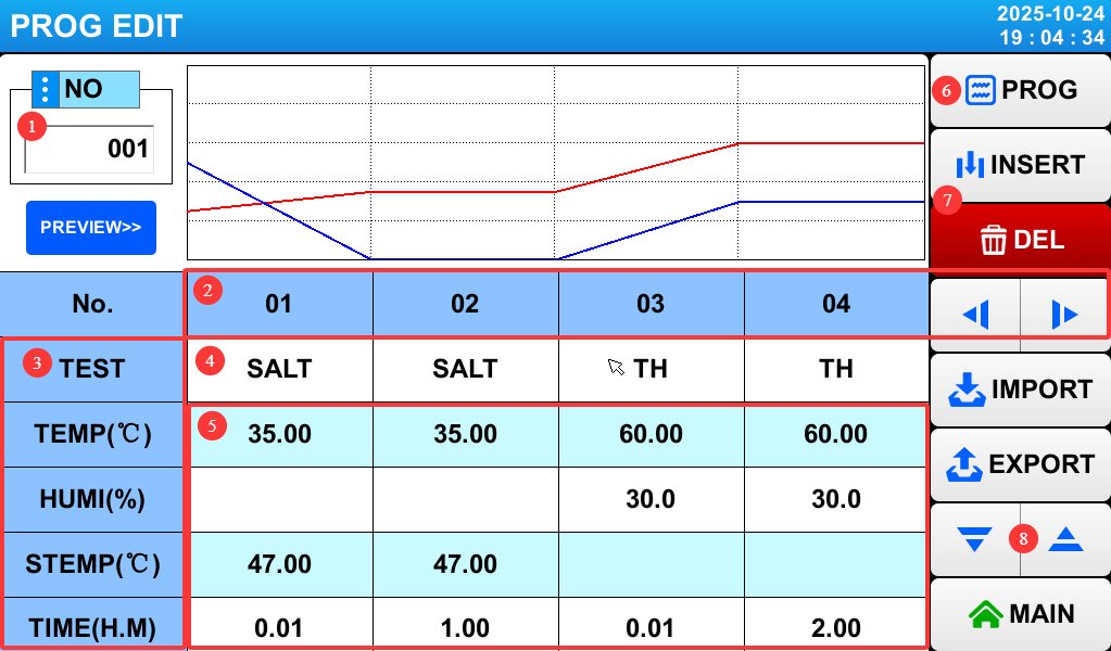
|
Project |
Nama |
Note |
|
① |
Nomor Program |
Enter the program number; up to 120 programs are supported. Be sure to avoid duplicating existing program numbers. |
|
② |
Test Segment Number |
Click the left and right arrow buttons on the right to switch to other test sections. |
|
③ |
uji Produk |
From top to bottom, in order: test mode, test chamber temperature, test chamber humidity, saturated bucket temperature, and test duration. |
|
④ |
Mode Tes |
Click to set the mode for the corresponding test section: Temperature and Humidity (TH), Salt Spray (SALT), Dry (DRY), or Stewing (STEWING). |
|
⑤ |
Pengaturan Parameter Pengujian |
For temperature and humidity (TH), set the chamber temperature and humidity; for salt spray (SALT), set the chamber temperature and the saturated bucket temperature; for drying (DRY), set the chamber temperature; For the Stewing (STEWING) test, none of these parameters need to be set . Test Duration Settings: With the same temperature and humidity settings, you must configure two consecutive test segments. The first segment is a transition phase and should be set to 1 minute (the actual duration may exceed 1 minute; the test chamber has a wait function that will reach the set temperature as quickly as possible and then automatically advance to the next segment). The second segment is the actual test duration. |
|
⑥ |
Click to return to the program settings screen. |
|
|
⑦ |
Click to insert or delete a test section. |
|
|
⑧ |
Press the up and down arrow keys to access the settings for other test items. |
Press the “Down” arrow key to access the “Spray” and “Defrost” settings screen:
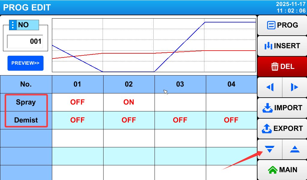
The spray function does not need to be enabled during the transition phase, temperature and humidity testing, drying testing, or static testing; simply set it to OFF. The spray function must be enabled—that is, set to ON—only during the actual salt spray test phase.
A defogging test segment can be added at an appropriate point, such as after each salt spray test segment. Set the test mode to “Stewing” and set the “Defogging” function to ON. Set the duration of the defogging test segment to 5 minutes.
4.5.2 Introduction to the Loop Settings Screen
Go to the “Cycle Settings” screen:

|
Project |
Nama |
Note |
|
① |
Pemilihan Program |
Select the currently set program number. |
|
② |
Jumlah siklus |
Indicate whether the current program should perform a loop. If a loop is not needed, simply enter 1—this means the program will run once. |
|
③ |
Program Links |
If you want this program to automatically connect to another program for testing after it finishes running, enter the corresponding program number; if not, simply enter 0. |
|
④ |
Siklus Parsial |
Loop sequence settings: If you want to test segments 1 through 2 of this program twice and segments 3 through 4 three times, set the three fields in the first column to 1, 2, and 2, respectively.and set the three windows in the second column to 3, 4, and 3, respectively. This means that the sequence of segments throughout the entire test program will be 1, 2, 1, 2, 3, 4, 3, 4, 3, 4, 5…, and so on. If this function is not needed, simply set all windows to 0. |
|
⑤ |
Click to return to the program settings screen. |
4.5.3 Introduction to the Standby Settings Screen
Wait Function and Wait Parameter Settings. If this function is enabled, the test timer will not start until the device reaches the target value (for salt spray tests, spraying will not begin until the test reaches the target temperature).
Go to the “Standby Settings” screen:
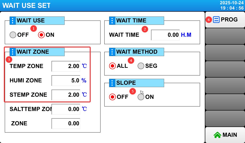
|
Project |
Nama |
Note |
|
① |
Wait Function |
Please set this to ON to enable the standby feature. |
|
② |
Waktu menunggu |
Set the maximum wait time. |
|
③ |
Waiting Range |
From top to bottom, in order: test chamber temperature, test chamber humidity, and saturated bucket temperature. |
|
④ |
Menunggu konfigurasi |
Just select “All,” and the wait function will be enabled for all test segments. |
|
⑤ |
Slope Mode |
Unless otherwise specified, please do not modify this setting; simply use the default value of 0, and the device will operate at the automatic slope. Setting any other value may cause the device to malfunction. |
|
⑥ |
Click to return to the program settings screen. |
4.5.4 Running the Program Test
Return to the “Monitoring Screen”:
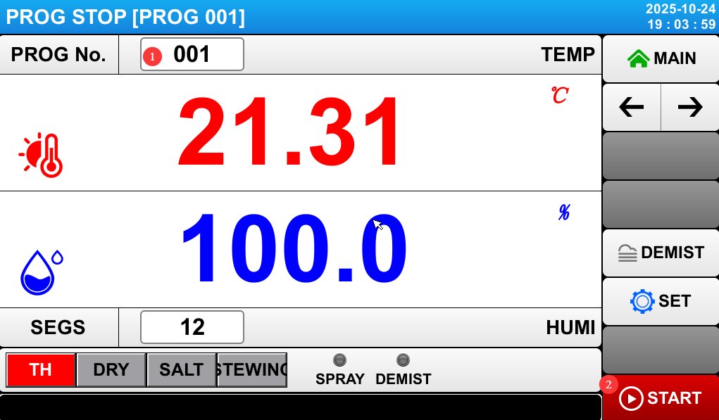
|
Project |
Nama |
Note |
|
① |
Pemilihan Program |
Enter the program number you want to run. |
|
② |
Run |
Click to start or stop the process. |
4.6 Memantau Proses Pengujian
4.6.1 Temperature and Humidity Monitoring
Monitor the temperature of the test chamber, the humidity inside the test chamber, and the temperature of the saturation chamber displayed on the touchscreen in real time. For temperature and humidity testing, the test chamber temperature will rise slowly to the target temperature, followed by the humidity slowly reaching the target level, after which the system will stabilize; For salt spray testing, both the chamber temperature and the saturated bucket temperature will gradually reach their target values simultaneously and then stabilize; for dry testing, the chamber temperature will gradually reach its target value and then stabilize. If temperature or humidity readings are abnormal, stop the test and refer to Chapter 6 for troubleshooting.
4.6.2 Pemantauan Permukaan Air
Pure Water Tank: Keep the water supply valve open at all times; the tank will automatically replenish the humidification chamber and the saturation tank. Humidification Chamber: Used for humidity testing, located inside the test chamber; no inspection is required. It is automatically replenished from the pure water tank without the need for manual intervention. Saturation Tank: If the water level drops to the alarm threshold, the system will automatically refill from the purified water tank. During refilling, the test will automatically pause temporarily and resume automatically once refilling is complete, requiring no manual intervention;
Brine Tank: The brine in the brine tank is used for spray testing and will be consumed; please refill it as described in Section 3.4.2. Gauze Tray Water Tank: The water in this tank is not consumed, and if the equipment is placed on a level surface, the water will not leak out, so refilling is generally not necessary.
4.6.3 Pemantauan Penyemprotan
Observe the spray pattern through the glass door of the mist chamber to ensure that the spray is uniform and uninterrupted. If any abnormalities are detected (such as a decrease in spray volume or water dripping from the nozzle), pause the test to check whether the nozzle is clogged or whether the air pressure is stable.
4.6.4 Perekaman Data
Record the test duration, laboratory temperature, laboratory humidity, saturated bucket temperature, brine level, and spray status every 2 to 4 hours; you can also export all historical data after the test is complete.
4.7 End of Test and Shutdown
4.7.1 Spray Shut-off and Defogging
Timed End: If a test duration has been set, the device will automatically stop spraying when the time elapses and enter the defogging mode (if the “End Defogging” function is enabled). Once defogging is complete, the touchscreen will display “Test Complete.”
Manual Stop: If you need to stop the test early, tap the “Stop” button on the touchscreen. The equipment will stop spraying, and you can choose whether to activate the defogging function (tap the “Manual Defogging” button). Once the salt fog has been expelled from the fog chamber, turn off the “Manual Defogging” button before proceeding with subsequent operations.
If a defogging test segment is configured in the program test, manual defogging is not required after the program test is complete.
4.7.2 Pengorganisasian Data dan Pengambilan Sampel
Data Organization: Record the total test duration, actual temperature curves, and any anomalies (such as mid-test water replenishment or alarms); export and save historical data; and organize the test record forms.
Removing the Sample: After the defogging process is complete, let the sample stand for 5 minutes. Wear acid- and alkali-resistant gloves, open the chamber door, and carefully remove the sample (taking care to prevent salt deposits from falling off the sample’s surface). Place the sample on a clean tray and label it with the relevant information (such as the test number and test duration).
4.7.3 Pemutusan Peralatan
Matikan kompresor udara atau lepaskan selang saluran masuk udara, dan matikan daya ke ruang uji.
5. Pemrosesan Pasca-Tes
5.1 Persiapan Sampel
5.1.1 Pembersihan dan Pengeringan Sampel
Pembersihan: Sesuai dengan persyaratan standar pengujian, bilas permukaan sampel secara perlahan dengan air murni (atau air suling) pada suhu ≤38°C untuk menghilangkan endapan garam yang tersisa. Hindari pembilasan yang terlalu kuat, karena dapat merusak produk korosi sampel (seperti lapisan karat atau lapisan oksidasi); Jika diizinkan oleh standar, sejumlah kecil deterjen netral (seperti sabun cuci piring) dapat digunakan untuk menghilangkan endapan garam yang membandel, diikuti dengan pembilasan menyeluruh dengan air murni.
Pengeringan: Setelah dicuci, gunakan kapas bersih dan bebas lemak atau kertas saring untuk menyerap kelembapan dari permukaan sampel, atau letakkan sampel di dalam lemari pengering berventilasi pada suhu ruangan (tanpa panas) untuk dikeringkan dengan udara. Hindari sinar matahari langsung atau pengeringan suhu tinggi untuk mencegah perubahan kondisi permukaan sampel.
5.1.2 Evaluasi Sampel
Inspeksi Visual: Periksa permukaan sampel untuk melihat tanda-tanda karat, perubahan warna, pengelupasan lapisan, penggelembunggan, dll. Catat area yang terkena korosi dan tingkat keparahan korosi (misalnya, ringan, sedang, parah). Ambil foto untuk perbandingan di masa mendatang.
Performance Testing: Depending on the purpose of the test, conduct follow-up performance tests on the samples (such as adhesion testing, impact resistance testing, and electrical performance testing) to evaluate the impact of salt spray corrosion on the samples’ performance, and compile an evaluation report.
5.2 Pembersihan Peralatan
5.2.1 Membersihkan Ruang Kabut
Bilas dinding bagian dalam ruang kabut, menara semprot, pengumpul kabut, dan sekat jaring dengan air murni untuk menghilangkan endapan garam dan kerak yang tersisa. Untuk noda membandel, gosok perlahan dengan sikat berbulu lembut yang dicelupkan ke dalam deterjen netral, lalu bilas hingga bersih dengan air murni.
Cleaning the Temperature Probe: Wipe the temperature probe with a soft cloth to remove any salt spray that has accumulated on it.
Cleaning the Humidity Sensor Gauze: If the gauze is soiled, remove it, clean it, and then reinsert it. If the gauze loses its ability to absorb moisture, it may cause abnormal humidity readings. Generally, replace the gauze every three months (use 100% cotton or medical-grade non-woven gauze).
5.2.2 Membersihkan Tangki Saturasi
Before cleaning, first close the automatic refill valve on the purified water tank, then drain the water from the tank. Open the drain valve on the saturation tank (located at the bottom of the test chamber), drain out any remaining water, close the drain valve, and then fill the tank with a 5% citric acid solution. Let it soak for 20–30 minutes (to remove scale from the inner walls of the tank), then drain the solution and rinse the tank 2–3 times with purified water to ensure no citric acid residue remains.
Cleaning the saturated tank liquid level sensor: Wipe the sensor probe with a soft cloth dipped in purified water to remove scale and ensure accurate liquid level detection.
5.2.3 Membersihkan Tangki Air Garam dan Nozel
Brine Tank: Rinse the inner walls of the tank with purified water to remove any residual brine and sediment. If there are salt crystals, soak the tank in warm water, then scrub them off. After rinsing thoroughly, let the tank air dry.
Nozzle Cleaning: Remove the nozzle and gently clear the small holes in the nozzle with a fine copper wire (diameter ≤ 0.5 mm), taking care not to apply excessive force that could damage the nozzle; Soak the nozzle in a 5% citric acid solution for 15 minutes to remove scale, then rinse thoroughly with purified water. Allow it to air dry before reinstalling (ensuring the small holes in the glass tube of the nozzle are aligned); If the nozzle is cracked, the orifice is deformed, or it fails to spray properly even after cleaning, replace it with a spare nozzle.
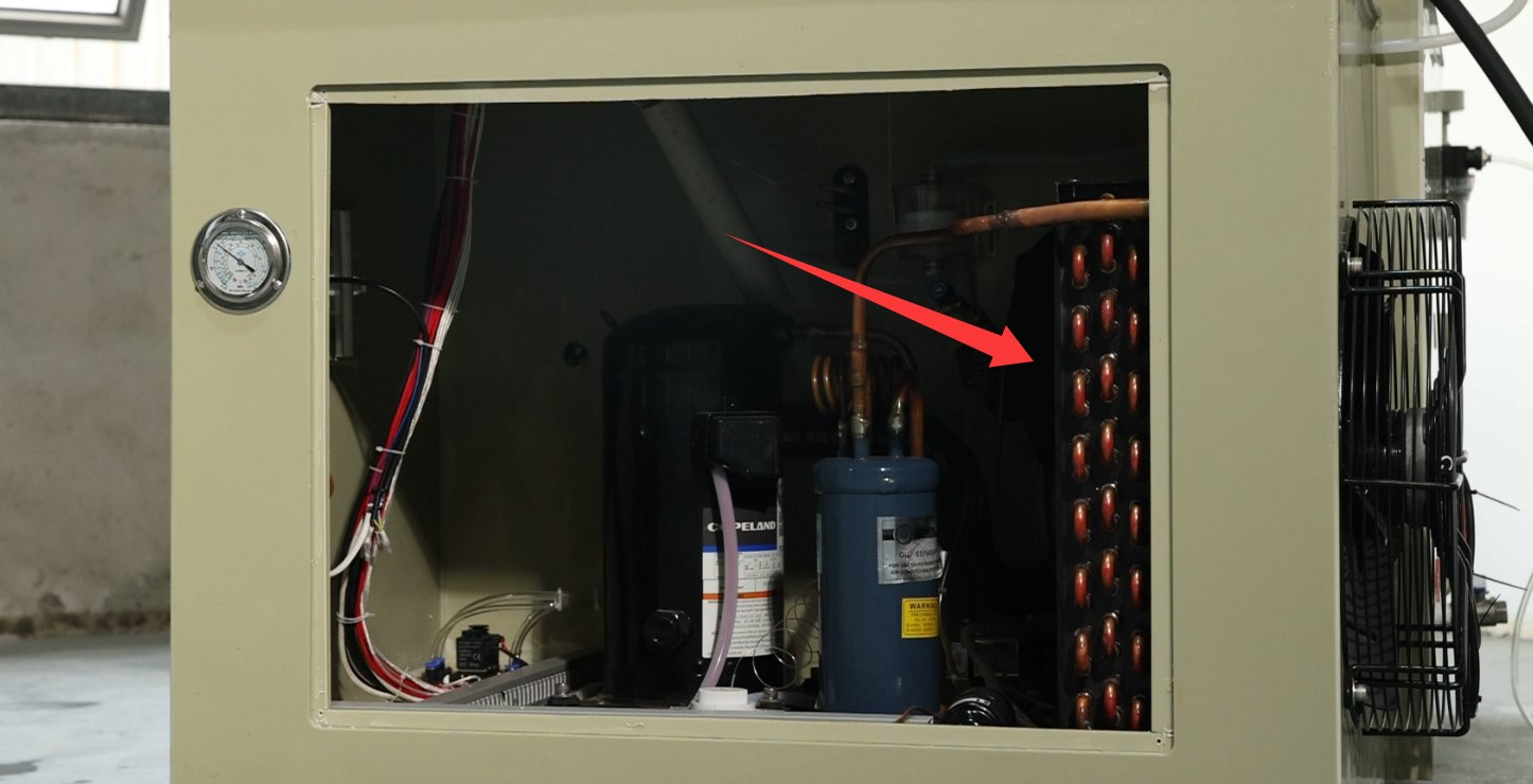
5.2.4 Sistem Pendingin
Use an air gun to remove dust and debris from the condenser fins, as shown in the figure below:
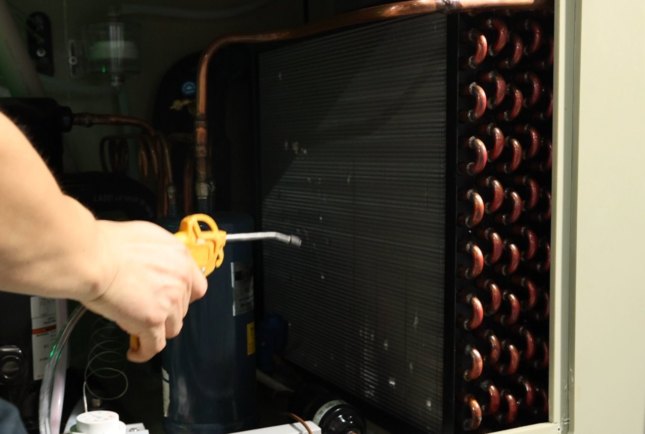
Check the refrigerant pressure (≥12 kg during operation) and top it off promptly if it is low.
5.3 Persyaratan Penyimpanan Jangka Panjang
5.3.1 Persiapan Sebelum Penyimpanan
Jika peralatan tidak akan digunakan dalam jangka waktu lama (lebih dari 1 bulan), lakukan langkah-langkah berikut:
Shut off water, electricity, and air: Disable the automatic refill function of the purified water tank; disconnect the equipment from the power source; disconnect the air hose from the air compressor; and turn off the air compressor’s power;
Thoroughly clean the equipment: Clean the fog chamber, saturation tank, brine tank, and nozzles according to the steps in “5.2 Equipment Cleaning” to ensure no salt residue remains;
Drain all liquids: Open all drain valves to remove any residual water from the components, and use compressed air to dry the interior (to prevent moisture and rust);
Melindungi Komponen: Tutupi peralatan dengan penutup debu untuk mencegah debu masuk.
5.3.2 Pemeliharaan Selama Penyimpanan
Kondisi penyimpanan harus memenuhi persyaratan yang ditentukan dalam Bagian 2.3.1;
Power on once a month: Turn on the power to the equipment and let it run for 30 minutes (no need to add water or brine) to prevent electrical components (such as capacitors and contactors) from deteriorating;
Lakukan pemeriksaan sebulan sekali: Buka penutup debu dan periksa bagian dalam peralatan untuk melihat adanya karat atau jamur; jika ditemukan, segera bersihkan dan keringkan. Periksa selang untuk melihat tanda-tanda penuaan dan pastikan sambungannya aman.
6. Mengatasi Masalah Umum
If the device malfunctions, please refer to the following common issues and troubleshooting steps:
|
Masalah umum |
Kemungkinan penyebab |
Prosedur |
|
Ruang Kabut / Tangki Saturasi Tidak Dipanaskan |
1. Level cairan tidak mencukupi; 2. Elemen pemanas terbakar; 3. Pengontrol suhu rusak; 4. Sensor suhu rusak |
1. Top off the fluid until the alarm clears; 2. Disconnect the power supply and check the resistance of the heating element (normally several tens of ohms); if it is burned out, replace it; 3. Restart the equipment; if there is still no response, contact customer service to have the controller repaired; 4. Check the probe wiring; if damaged, replace it. |
|
Tidak disemprot |
1. Larutan garam tidak cukup; 2. Nosel tersumbat; 3. Kebocoran udara (misalnya, selang udara terputus, katup solenoid rusak); 4. Penyesuaian tekanan udara yang tidak tepat |
1. Refill with saline solution; 2. Clean the nozzle (see 5.2.3); 3. Check the air tube connections and replace any damaged solenoid valves; 4. Readjust the air pressure (0.2 MPa at the back, 1 kg/cm² at the front) |
|
The temperature cannot reach the setpoint |
1. Daya elemen pemanas tidak mencukupi; 2. Sensor ketinggian cairan tidak berfungsi (tampilan ketinggian cairan tidak normal); 3. Suhu lingkungan terlalu rendah; 4. Segel pintu kurang rapat. |
1. Check the heating element’s wattage and replace it with a compatible one; 2. Clean or replace the liquid level sensor; 3. Adjust the ambient temperature (e.g., turn up the heat); 4. Check the water level in the sealing tank and top it off to the standard level. |
|
Pengukur tekanan depan tidak dapat disetel ke pembacaan yang lebih tinggi. |
1. Katup pengisian air manual pada tangki tekanan tidak tertutup; 2. Selang udara nosel longgar atau retak; 3. Katup solenoid semprot rusak. |
1. Tutup katup pengisian air manual; 2. Ganti atau sambungkan kembali selang udara; 3. Ganti katup solenoid. |
|
Humidity Display Error |
Humidity sensor gauze malfunction; 2. Humidifier water tank malfunction |
Clean or replace the gauze; 2. Remove the rear panel from the inner compartment and check the condition of the humidifier water tray. |