Inggris
 中文简体
中文简体 Русский
 Español
 Português
 Türkçe
 العربية
 Deutsch
 Polski
 Italiano
 Français
 한국어
한국어 ไทย
ไทย Tiếng Việt
 日本語
日本語





























Ruang Uji Penuaan Lampu Xenon
Pengguna manual
berlaku LISUN models: XD-150LS
1. Pemahaman Dasar tentang Peralatan
1.1 Spesifikasi Teknis Utama
| LISUN Pilih Model | XD-150LS | XD-010LS | XD-010LF |
| Dimensi Kabinet | |||
| Inner Chamber Dimensions (Depth × Width × Height) | 500 × 600 × 500 mm | 1000 × 1000 × 1000 mm | |
| Dimensions (Depth × Width × Height) | 1030 × 1130 × 1900 mm | 1730 × 1430 × 2100 mm | |
| In-Chamber Sample Test Rack | Flat-bed type: Plate dimensions 460 × 550 mm | Flat-plate type: Plate dimensions 960 × 960 mm | Rotary drum type: Holds 66 standard samples, each measuring 190 × 70 mm |
| Suhu | |||
| Temperature Range Inside the Chamber | RT–80°C | ||
| Suhu Papan Tulis | 45 – 85 ° C | ||
| Kelembaban | |||
| kelembaban Rentang | 20–95% R. H. | ||
| Penerangan | |||
| Intensitas Radiasi Lampu Xenon | 0.30–0.57 W/m² (at 340 nm), adjustable; 0.66–1.22 W/m² (at 420 nm), adjustable; 35–70 W/m² (300–400 nm), adjustable;300–1200 W/m² (300–800 nm), adjustable | ||
| Spectral Wavelengths of Xenon Light | 280-800 nm | ||
| Probe Iradiasi | Irradiance measurement range: 0.1–5000 W/m²; Accuracy: ±5%; Repeatability: ±1%; Cosine characteristic: f2′ ≤ 4%; Response time: 1 second | ||
| Spesifikasi Filter | Boric Acid Glass Filters | Complete Set of Filters | |
| Xenon Lamp Cooling Methods | Berpendingin udara | Water-cooled (includes a chiller and water purifier) | |
| Alat penyiram | |||
| Watering Time | 1–999 menit (dapat disesuaikan) | ||
1.2 Membuka Kemasan dan Memeriksa Isinya
1.2.1 Membuka Kemasan dan Pemeriksaan Visual
When unpacking the equipment, handle it gently to avoid scratching the exterior with sharp tools. After unpacking, first inspect the exterior of the main unit to ensure there are no visible deformations, dents, or peeling paint, and that the panel instruments and buttons are not damaged or loose. If you find that the device or any accessories are damaged or deformed, do not power it on. Contact LISUN Layanan pelanggan segera.
1.2.2 Tipe host
1 XD Series Xenon Lamp Aging Test Chamber.
1.2.3 Bahan Habis Pakai dan Aksesoris
Open the spare parts box. Standard spare parts include: ① humidification tube, ② solid-state relay, ③ T33 filter, ④ gauze for the humidity probe.
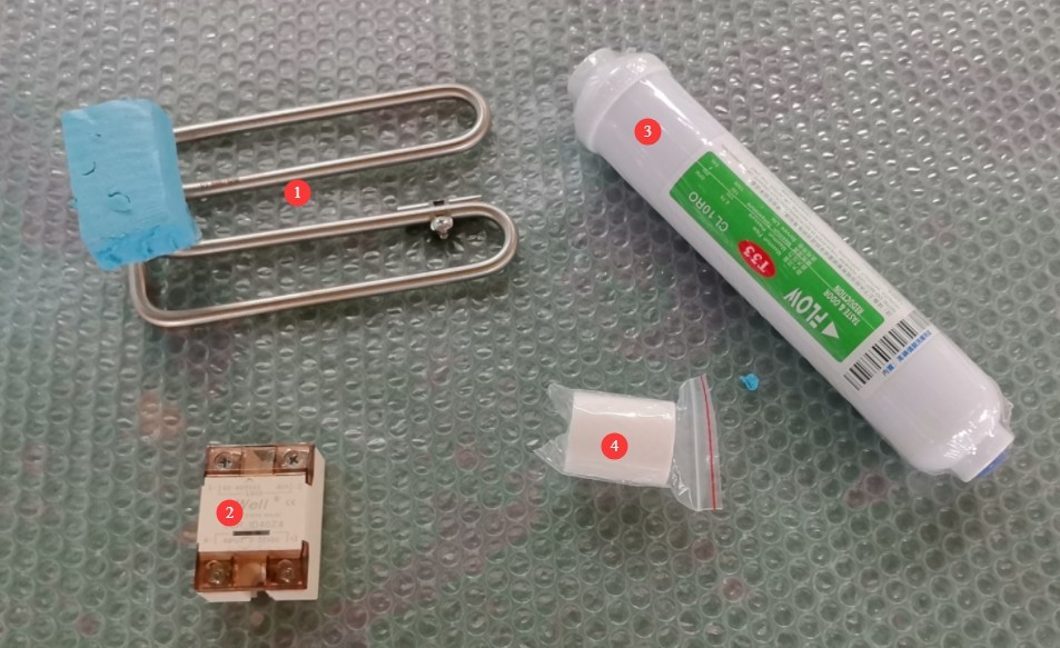
Gambar 1
Tautan unduhan untuk manual pengguna digital, kartu garansi, dan dokumen lainnya telah dikirimkan kepada Anda melalui email. Silakan unduh sesegera mungkin. Jika Anda melewatkan email tersebut, jangan ragu untuk menghubungi kami agar dapat menerima tautan unduhan lagi.
1.3 Deskripsi Struktur Peralatan
Front of the test chamber: ① Touchscreen; ② Power switch and emergency stop button; ③ Communication port, used for exporting test curves, etc.;④ Test chamber door; ⑤ Sample shelf, with Optical Fibers and a blackboard also mounted on the shelf (please take care to avoid and protect the Optical Fibers and blackboard when working inside the chamber); ⑥ Spray system and xenon lamp at the top; ⑦ Manual water-filling drawer; ⑧ Water level viewing window.
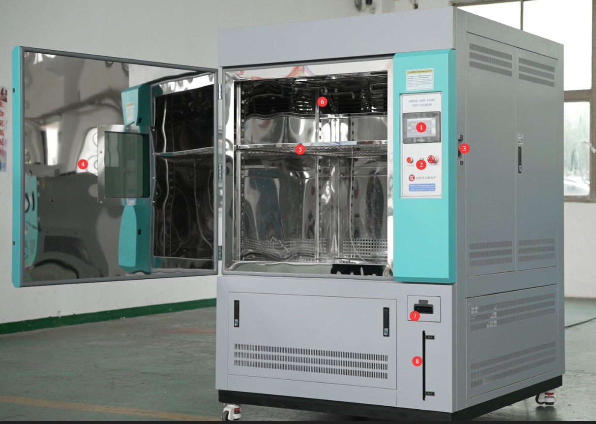
Gambar 2
Locations of the temperature and humidity sensors inside the test chamber: ① Temperature sensor; ② Humidity sensor and humidity sensor water tray.
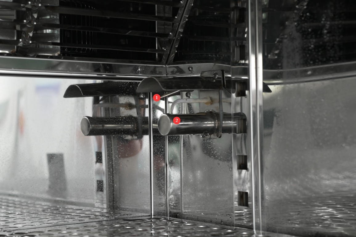
Gambar 2.1
Rear of the test chamber: ① Power circuit breaker; ② Compressor refrigerant pressure gauge; ③ Water tank drain; ④ Humidifier (boiler) drain; ⑤ Power cord; ⑥ Automatic water refill port (functions the same as the water-filling drawer on the front of the test chamber; one is for manual refilling, and the other is for automatic refilling).
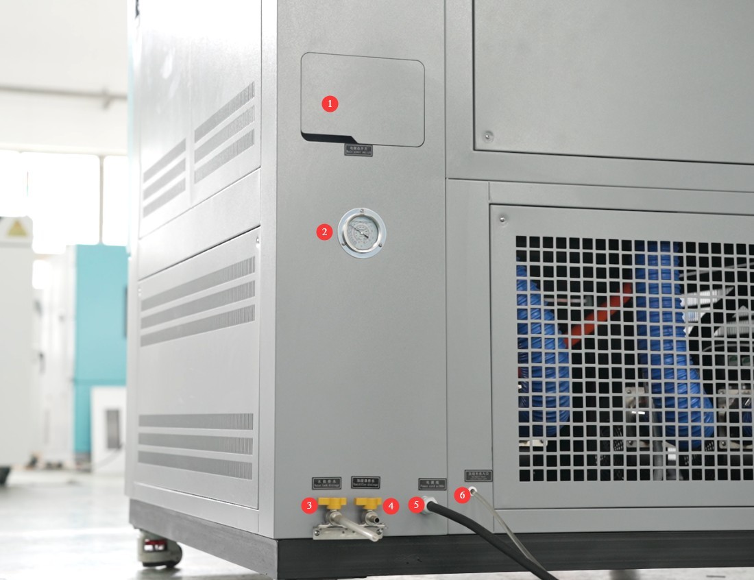
Gambar 3
Note: Connect the water pipes marked ③ and ④ to the drain. If the equipment will not be used for an extended period, drain all water from the interior.
2. Tindakan Pencegahan Keamanan
2.1 Keamanan Listrik
2.1.1 Koneksi Daya
The equipment must be powered by a dedicated circuit with a three-phase, five-wire configuration rated at AC 380 V, 50 Hz (or 60 Hz, optional). Multiple units must not share a single power source to prevent voltage drops that could cause abnormal equipment performance or failure-induced shutdowns. Before connecting the power supply, ensure the power is turned off. When wiring, strictly distinguish between the live wires (L1, L2, L3), neutral wire (N), and ground wire (PE). The wiring sequence must comply with the requirements of the equipment’s electrical schematic; reversing the live and neutral wires is strictly prohibited.
The equipment is equipped with a phase sequence protector. After wiring, check the phase sequence status before applying power: If the “Normal” green light on the phase sequence protector is on, it indicates that the power supply and wiring are correct; if any other light is on, check the power supply voltage, frequency, or phase sequence accordingly. If there is a phase sequence issue, simply swap the positions of the two adjacent live wires (L1 and L2) and check again.

Gambar 4
2.1.2 Spesifikasi Pembumian
The equipment must be properly grounded. The grounding terminal is located on the back of the equipment; the grounding wire must have a cross-sectional area of at least 4 mm², and the grounding resistance must be 50 Ω or less (to be verified using a Grounding Resistance Tester).
Do not connect the ground wire to gas lines, non-metallic water pipes (such as PVC pipes), or other non-dedicated grounding devices; if connecting to a metal water pipe, ensure that the pipe is grounded and has no anti-corrosion insulation.
2.1.3 Kontraindikasi untuk Prosedur
Before connecting wires, performing maintenance, or replacing parts, you must turn off the main circuit breaker on the back of the equipment and disconnect the external power supply. Verify that there is no residual voltage before proceeding.
Do not touch the power switch, touchscreen, or terminal blocks with wet hands to avoid electric shock; do not place water cups or damp items near the equipment to prevent liquids from seeping into the electrical control cabinet.
Do not place any foreign objects (such as tools or paper) inside the electrical control cabinet to prevent dust or foreign objects from causing short circuits or damaging components.
Do not plug in or unplug power cords or signal cables while the equipment is running, to prevent short circuits that could damage the controller or electrical components.
2.2 Keselamatan Operasional
2.2.1 Persyaratan Spesimen Uji
It is strictly prohibited to store flammable or explosive substances (such as alcohol, gasoline, and paint thinners), toxic substances (such as chemicals and corrosive reagents), or highly corrosive substances (such as acid and alkali solutions) in this equipment, which is not equipped with explosion-proof devices. Improper storage may result in fire or explosion.
If the test specimen generates heat (such as a component with an electrical function), an external power source must be used; do not connect it directly to the device’s power port to avoid overloading the device’s circuitry.
Test specimens (such as coated samples) must be allowed to air-dry outside the chamber beforehand to remove any residual impregnating material. Do not place specimens containing liquid directly into the chamber, as this may cause liquid to drip onto the heating elements or sensors, resulting in malfunctions.
2.2.2 Keselamatan Operasional
While the equipment is in operation, non-professionals are prohibited from disassembling or repairing any components (including the electrical control cabinet, xenon lamp tubes, nozzles, sensors, etc.). If maintenance is required, the machine must be shut down and the power disconnected, and the work must be performed by personnel authorized by the manufacturer.
Avoid opening the chamber door as much as possible during operation: Under high-temperature (≥60°C) or high-humidity (≥80% RH) conditions, opening the door may cause hot, humid air to rush out, resulting in burns; If you must open the door, first shut down the unit, wait until the temperature drops below 50°C and the humidity drops below 60% RH, and then slowly open the door while wearing heat-resistant gloves.
Do not set the temperature, humidity, or light intensity beyond the equipment’s rated range (e.g., the temperature must not exceed RT–95°C; refer to Section 1.1, “Core Parameters,” for specific values). Setting values outside this range may result in the burnout of heating elements, damage to xenon lamps, or deterioration of test specimens.
Test specimens must be placed evenly inside the chamber; overcrowding is prohibited: Leave a space of at least 5 cm between the specimens and the chamber walls, as well as between the specimens themselves, to ensure smooth circulation of hot air and prevent localized overheating that could lead to testing data discrepancies.
If the equipment triggers an alarm (e.g., overtemperature, sensor failure), immediately shut down the machine, check the error code (see Section 6.1, “Troubleshooting”), and restart the machine only after the problem has been resolved. Do not force the machine to continue operating while the alarm is active.
2.2.3 Perilaku yang Dilarang
Do not remove the nozzle, temperature/humidity sensors, or heating elements without authorization during operation. Modifying the equipment will void the warranty and may result in safety incidents.
There are strict operating guidelines for xenon lamps: The interval between each start-up and the next must be at least 5 minutes; frequent start-stop cycles are prohibited (to prevent shortening the lamp’s lifespan or causing it to shatter). After the test is complete, wait for the xenon lamp to cool down gradually (10 minutes); do not turn off the power immediately.
Do not touch the touchscreen with hard objects (such as screwdrivers) to prevent scratches or malfunctions; do not wipe the touchscreen or the device casing with organic solvents such as alcohol or gasoline; clean with a dry cloth instead.
2.3 Keselamatan Lingkungan
2.3.1 Persyaratan Instalasi
The equipment must be placed in an air-conditioned room, with the ambient temperature maintained between 5 and 25°C (do not exceed 30°C to prevent overloading of the refrigeration system), relative humidity below 85%, and no direct sunlight (to prevent aging of the enclosure and internal temperature fluctuations).
The installation environment must be well-ventilated and low in dust, and must be located away from flammable or explosive gases (such as natural gas and liquefied petroleum gas) and corrosive gases (such as laboratory exhaust fumes) to prevent component corrosion or the risk of fire.
Do not pile up clutter (such as cardboard boxes or reagent bottles) around the equipment; ensure proper airflow to facilitate heat dissipation (especially for the condenser in the refrigeration system).
2.3.2 Persyaratan Ruang
A clearance of at least 1500 mm must be maintained between the equipment enclosure and the wall, as well as surrounding equipment (such as other test chambers or cabinets), to ensure that the side and rear panels can be opened for maintenance without impeding heat dissipation.
Allow at least 2000 mm of space in the direction the equipment door opens to prevent it from colliding with other objects when opened and to ensure easy access for loading and unloading test specimens.
2.3.3 Penempatan Horizontal
The equipment must be placed on a level surface and calibrated using a level: Place the level on a flat surface on top of the equipment and ensure that the bubble is centered. Note: The following types of legs are adjustable to ensure the test chamber is level:
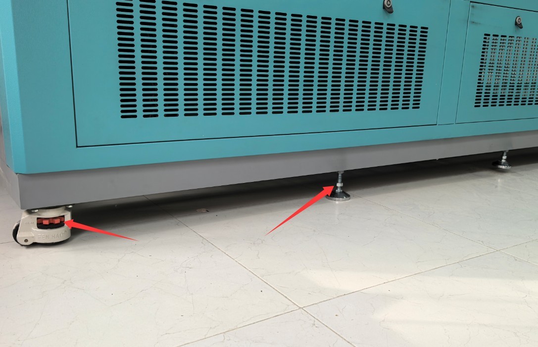
Gambar 4.1
If the equipment is tilted, this may result in: ① Water leakage from the tank; ② Uneven hot air circulation, leading to deviations in test data; ③ Stress on the refrigeration system piping, increasing the risk of leaks; ④ Uneven alignment of the test chamber door.
2.4 Lainnya
Untuk hal-hal yang tidak tercakup dalam panduan ini, harap berhati-hati atau hubungi kami.
3. Persiapan Sebelum Ujian
3.1 Filling the Water Tank (See Section 1.3 for the locations of the various components)
Before adding water, check whether the drain valve on the water tank is in the “closed” position (the valve is closed when it is parallel to the tank body and open when it is perpendicular); if the drain valve is not closed, close it immediately to prevent water leakage from the tank;
Open the device’s water-filling drawer and check inside the drawer and the water tank (to inspect the water tank, you’ll need to open the bottom panel on the right side of the device) for any debris or standing water (clean the inside of the water tank before first use); if the automatic water refill port is connected to a water source, the tank will be refilled automatically;
The water tank is located as shown in the figure below:
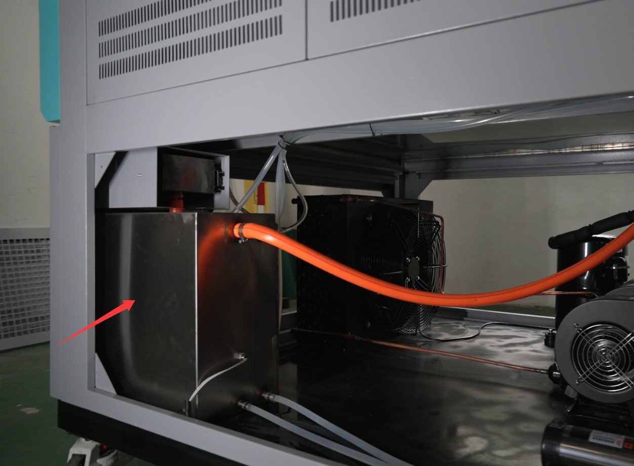
Gambar 5
The water tank must be filled with purified water (do not use tap water or bottled water, to prevent limescale from clogging the humidifier or corroding the water lines). When filling the tank, check the water level markings until the water reaches the “MAX” line (do not exceed this level to prevent overflow). Close the water tank drawer after filling;
3.2 Starting Up The Xenon Lamp Aging Test Chamber
Verify that the external power supply and ground connection are correct, close the equipment door, and close the main circuit breaker on the back of the equipment (flip it upward to the “ON” position).
Press the “Power” button on the control panel, and after 5 seconds, the meter will automatically return to the main screen.
After powering on, check the instrument for any alarm messages (such as “Low Water Level” or “Sensor Failure”). If an alarm occurs, first refer to Chapter 7 for troubleshooting (e.g., add water, check sensor wiring); if no alarm is present, the unit enters standby mode, and you can proceed with parameter settings.
After startup, the water pump will automatically supply water to the humidification system. After 5–10 minutes, check the water level in the humidity sensor’s water tray (the gauze wrapped around the humidity sensor must be completely saturated) and check the water level in the humidification boiler (open the right-side panel of the unit to verify), ensuring that the heating element inside the boiler is completely submerged in water(to prevent dry heating).
The location of the humidifying boiler is shown in the figure below:
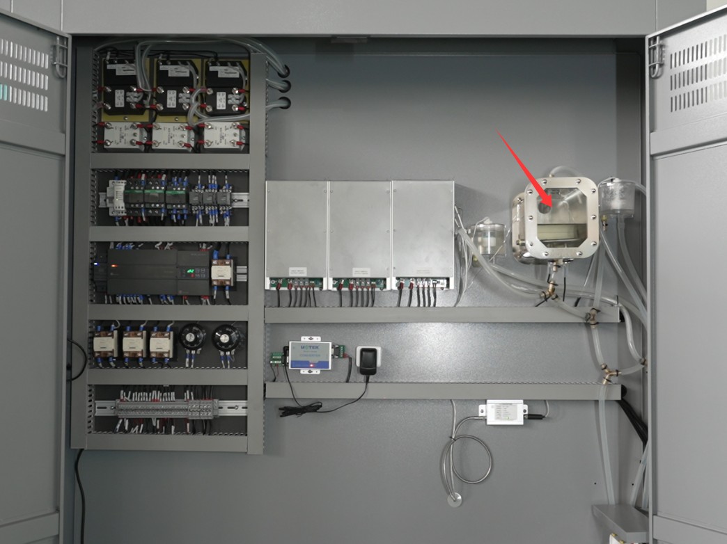
Gambar 6
3.3 Prosedur Penempatan Sampel
3.3.1 Contoh Penempatan
Open the test chamber door, adjust the height of the interior shelves, and place the test specimens evenly on the shelves: ① Do not cover the temperature/humidity probes (especially the gauze covering the humidity probe, which must remain exposed); ② Do not cover or obstruct the Optical Fibers or the blackboard; ③ Avoid touching the xenon lamp, air ducts, or spray nozzles.
3.3.2 Menutup Pintu Kabinet
Gently push the cabinet door to ensure it fits snugly against the weatherstripping, leaving no gaps (if there are any gaps, check whether the door has sagged or the weatherstripping has deteriorated; make minor adjustments to the door hinges or clean the weatherstripping).
After closing the door, make sure the latch is securely engaged to prevent the door from opening unexpectedly during operation.
4. Operating the Touchscreen Program for Xenon Lamp Aging Tests
4.1 Pengaturan Operasi
Buka layar “Pengaturan Operasi”:
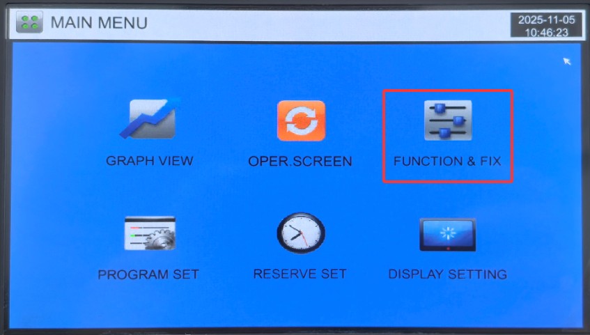
Gambar 7
The following parameters can be configured: ① Operating mode selection: choose between “Fixed-Value Operation (FIX)” or “Programmed Operation (PROG)”; ② Spray parameters: spray duration and interval time; ③ End settings: whether to automatically return to room temperature after the test; if so, please also set the room temperature range;④ Operating parameters and on/off settings for the three xenon lamps: Do not modify these parameters, and keep the switches for the three lamps on the right in the “on” position (red indicates “on”); ⑤ Channel selection: Before testing, you must correctly select the required channel, as the maximum illuminance value varies for each channel.
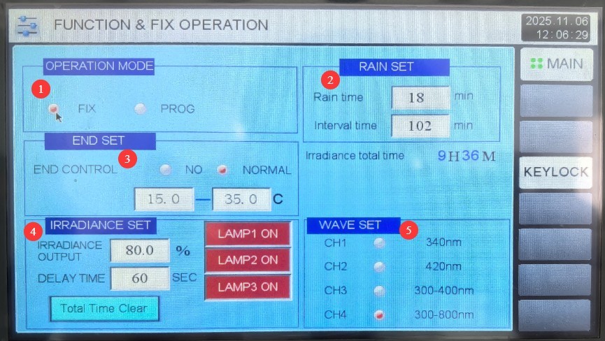
Gambar 8
4.2 Pengaturan Janji Temu
Buka layar “Pengaturan Penjadwalan”:
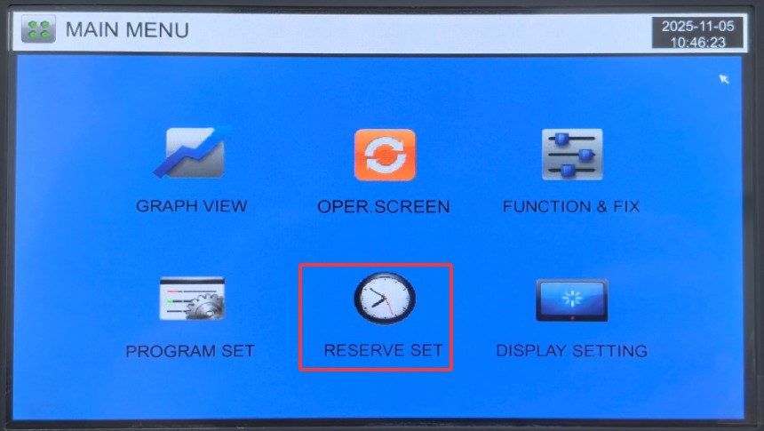
Gambar 9
The left column displays the current time, and the right column allows you to enter the scheduled time; the test chamber will then automatically begin the shock test at the scheduled time:
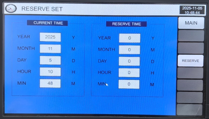
Gambar 10
4.3 Pengaturan Tampilan
Buka layar “Pengaturan Tampilan”:
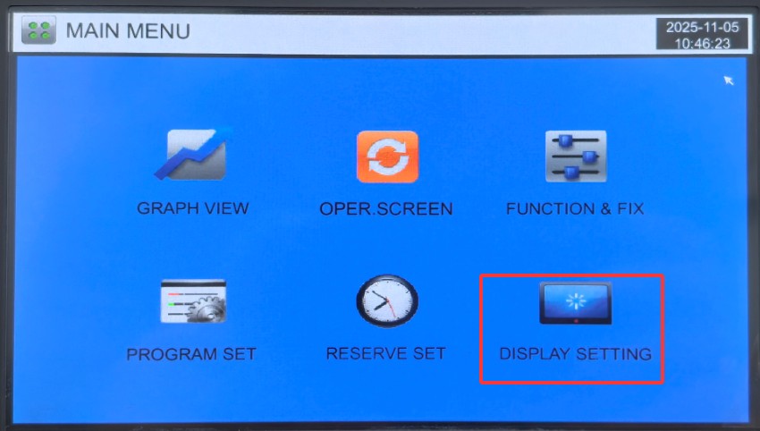
Gambar 11
You can configure the display language, the startup method after an unexpected power outage (Stop: After a power outage during operation, the system returns to the “Stop” state when power is restored; Cold Start: After a power outage during operation, the system restarts from the first segment and resumes operation when power is restored; Hot Start: The operation where, after a power outage during operation, the system continues from the stage it was in before the outage and restores the status to the state prior to the power outage when power is restored.), backlight duration, etc.:
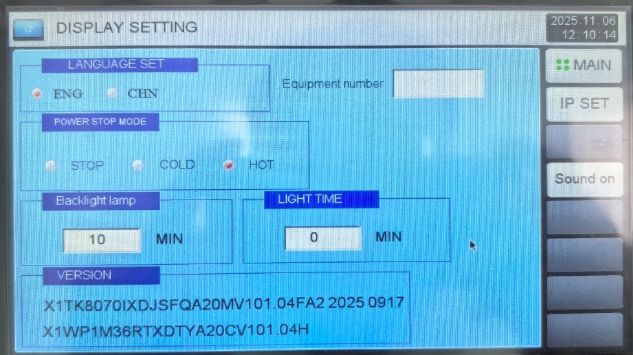
Gambar 12
4.4 Fixed-Value Operation (Single-Parameter Test)
Go to the “Operation Settings” screen, select the operation mode, and choose “Fixed-Value Operation (FIX).”
4.4.1 Pengaturan Parameter
Go to the “Monitoring Screen”:
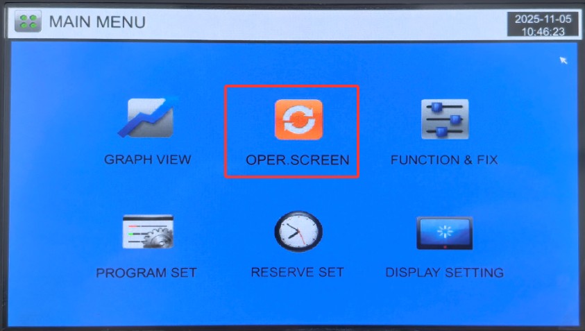
Gambar 12.1
Click “Settings” on the right:
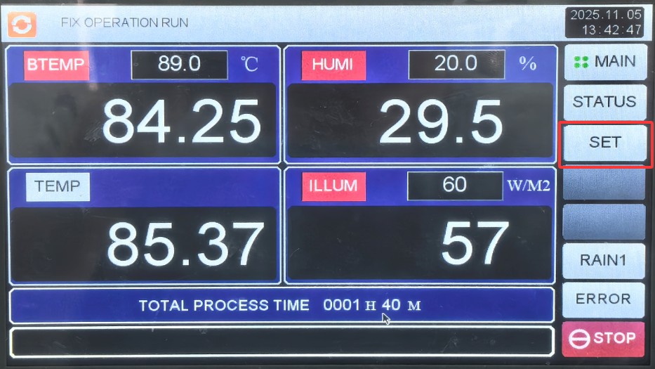
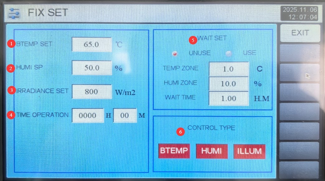
Gambar 13
① Blackboard temperature (unless otherwise specified, the test chamber temperature is uncontrollable; please set the blackboard temperature, and the test chamber temperature will automatically adjust based on it); ② Test chamber humidity; ③ Light intensity; ④ Timer settings (enter the test duration; if set to 0, the test must be stopped manually);⑤ Wait setting: If the wait function is selected, the test chamber will not begin calculating the test time until it reaches the set temperature and humidity. If the wait function is required, you must also set the wait tolerance (the test is considered complete if the values fall within this tolerance range) and the wait time (if the test chamber has not reached the target temperature and humidity after this wait time has elapsed, it will automatically begin calculating the test time);⑥ Control Type Selection: Please select the control function type required for this constant-value test.
Gambar 13.1
4.4.2 Startup dan Operasi
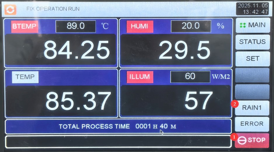
① Go to the “Monitoring Screen” and click “Run” in the lower-right corner. ② To activate the spray system simultaneously, click “Internal Spray” in the lower-right corner; the spray system will operate according to the parameters set in Section 4.1. Note: When the spray system is active, humidity testing and display results may be abnormal. Figure 14
4.5 Program Operation (Multi-Stage Parameter Cycle Test)
Go to the “Operation Settings” screen, select the operation mode, and choose “Program Run (PROG).”
4.5.2 Introduction to the Program Screen
Go to the “Program Group Settings” screen:
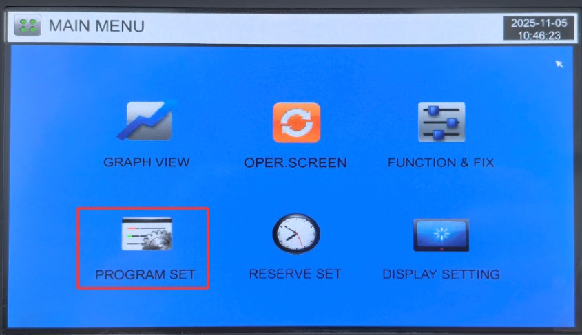
Gambar 15
① Set the program group number (1–100), ensuring it does not conflict with existing programs; ② Customize the program test name; you may use standard names for identification, such as Method A in Table B.2 of ISO 4892-2:2013; ③ Edit the program group; ④ Set the number of cycles; ⑤ Set the wait time.
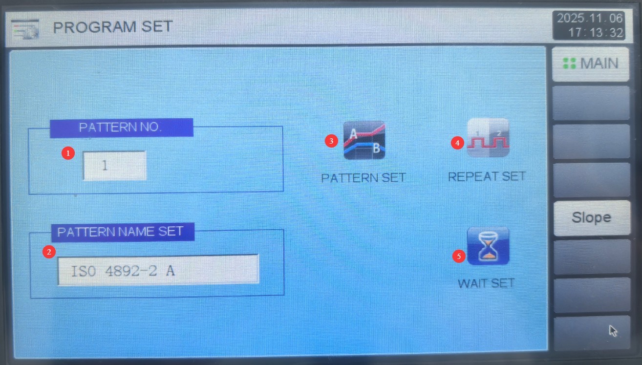
Gambar 16
The requirements of Method A in Table B.2 of ISO 4892-2:2013 are as shown in the figure below:
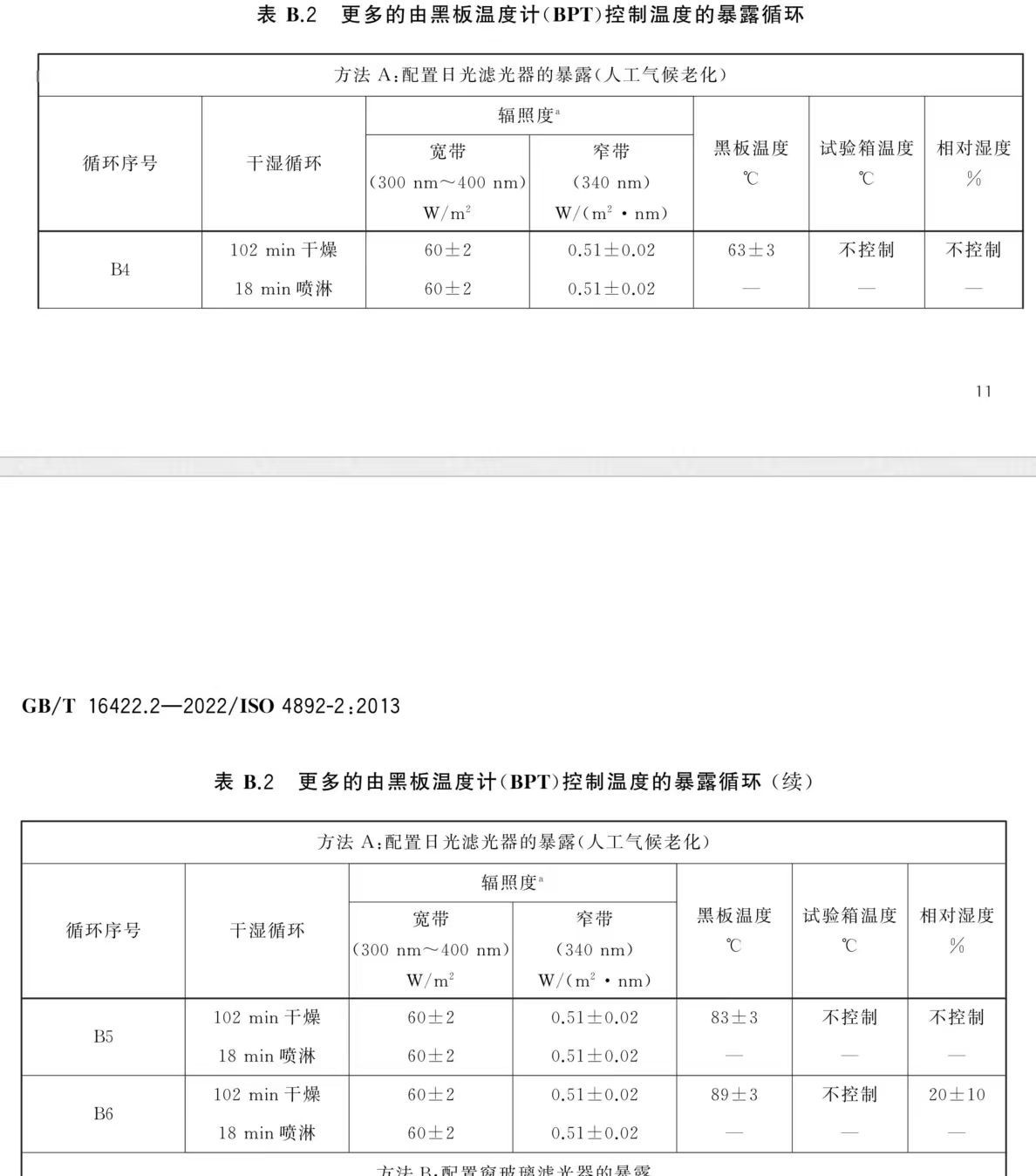
Gambar 16.1
4.5.2 Introduction to the Program Editor Screen
Go to the “Program Group Edit” screen. Edit the parameters for each test segment in the area shown in the figure below. Note: Each set of parameters must include the same two segments. The first segment is the transition segment—the time it takes for the device to reach that parameter—which should be set to 1 minute (the program has a wait function, so it will actually take longer than 1 minute; the device will reach the set parameter as quickly as possible and then automatically proceed to the next segment). The second segment is the actual test duration. Note: All parameters must be set in accordance with the standard requirements and cannot be set arbitrarily:
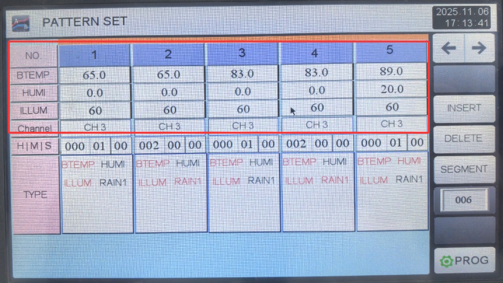
Gambar 17
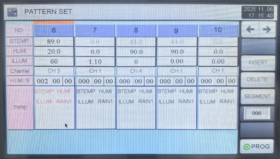
Gambar 17.1
Click the blank area indicated by the arrow below each test segment in the image below. The left sidebar will display the function buttons shown in the image. If a test segment requires a specific function, toggle it to green; if a test segment does not require certain functions, toggle it to white:
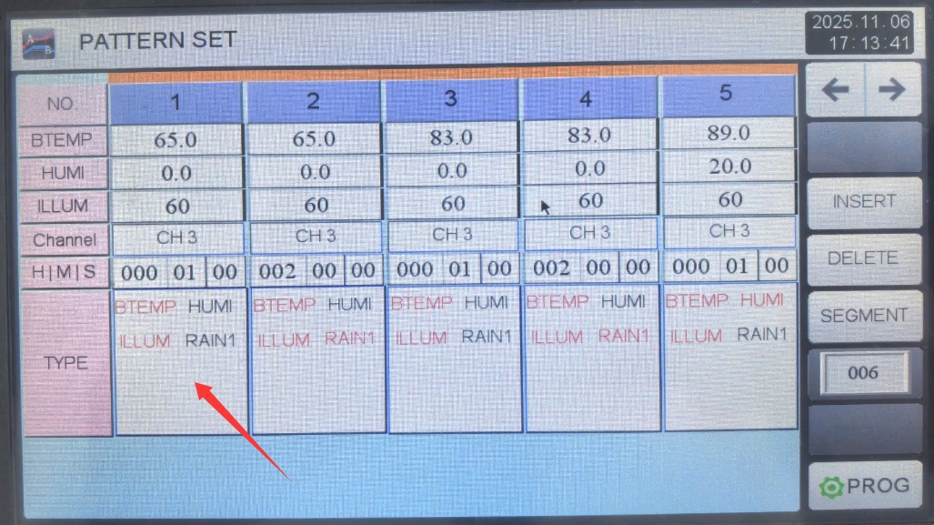
Gambar 18
After editing the program set, be sure to enter the number of program segments you want to run in the input box shown in the figure below. For example, if you enter 006, only the first 6 segments will be executed when the program runs.
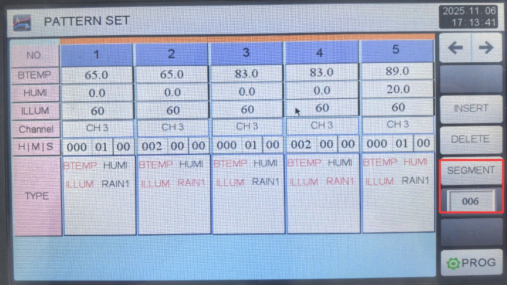
Gambar 19
For example, if you need to perform the complete Method A test specified in Table B.2 of ISO 4892-2:2013, you must set up six segments. Stages 1 and 2 are B4, with a total duration of 2 hours of drying and spraying, illuminance of 60 at 300 to 400 nm (either this or an illuminance of 0.51 at 340 nm may be selected), and a black panel temperature of 63; Stages 3 and 4 are B5, with a total duration of 2 hours of drying and spraying, illuminance of 60 at 300 to 400 nm, and a black panel temperature of 83; Stages 5 and 6 are B6, with a total duration of 2 hours for drying and spraying, illuminance of 60 at 300–400 nm, and a blackboard temperature of 89; relative humidity is 20.
4.5.2 Introduction to the Cycle Settings Screen
Go to the “Loop Settings” screen. ① Loop Count: Indicates whether the current program should run in a loop. If not required, enter 1; the program will then run once and terminate. ② Program Link Settings: If you want the program to automatically link to another program for testing after it completes, enter the corresponding program number; if not required, enter 0.③ Segment Loop Settings: If you want segments 1 through 2 of this program to be looped twice and segments 3 through 4 to be looped three times, set the three windows in the first column to 1, 2, and 2, respectively; and set the three windows in the second column to 3, 4, and 3, respectively. This means the sequence of segments throughout the entire program will be 1, 2, 1, 2, 3, 4, 3, 4, 3, 4, 5…, etc. If this function is not needed, set all windows to 0.
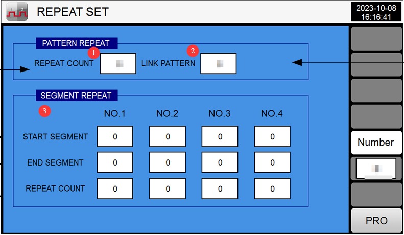
Gambar 20
4.5.3 Introduction to the Wait Settings Screen
Go to the “Wait Setting” screen. ① Under normal circumstances, select “All,” which enables the wait function for all segments;② Wait Range: For example, if the wait range temperature is set to 0.5 and the target temperature for the transition stage is set to 50 degrees Celsius, when the chamber temperature reaches a range between 49.5 and 50.5 degrees Celsius, it is deemed to have reached the target temperature, and the system will proceed to the next stage;③ Wait Time: You can set the maximum wait time as needed. For example, if the wait time is set to 2 hours, and the parameters still do not reach the target value after the unit has waited for 2 hours, it will automatically proceed to the next stage.
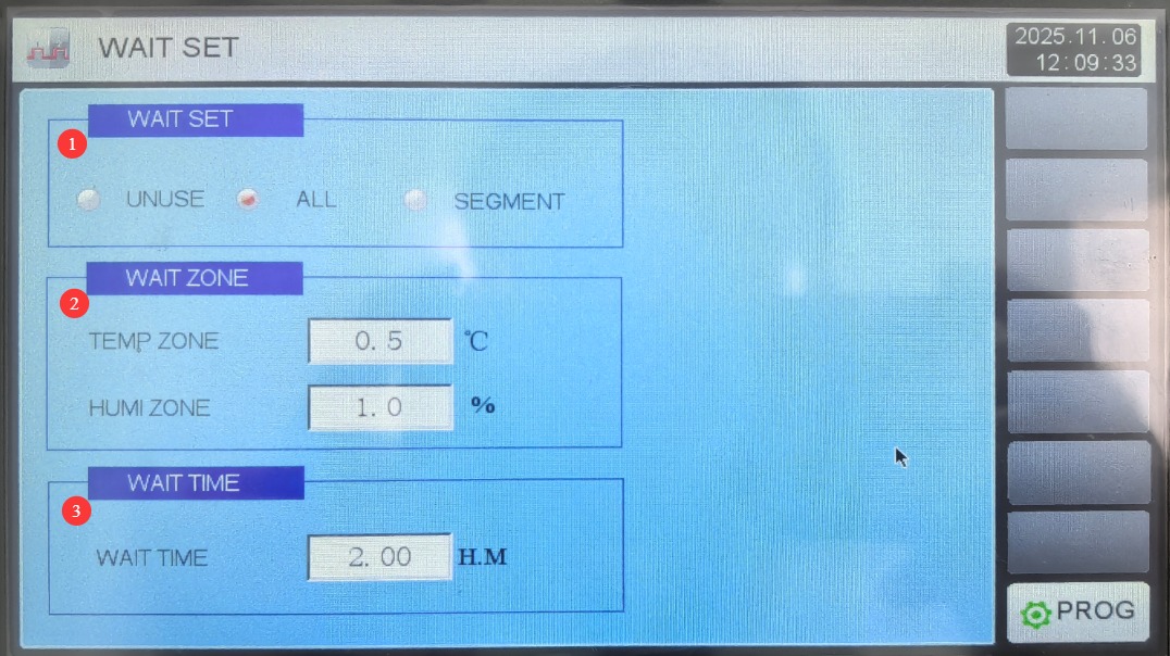
Gambar 21
4.5.4 Starting Up and Running
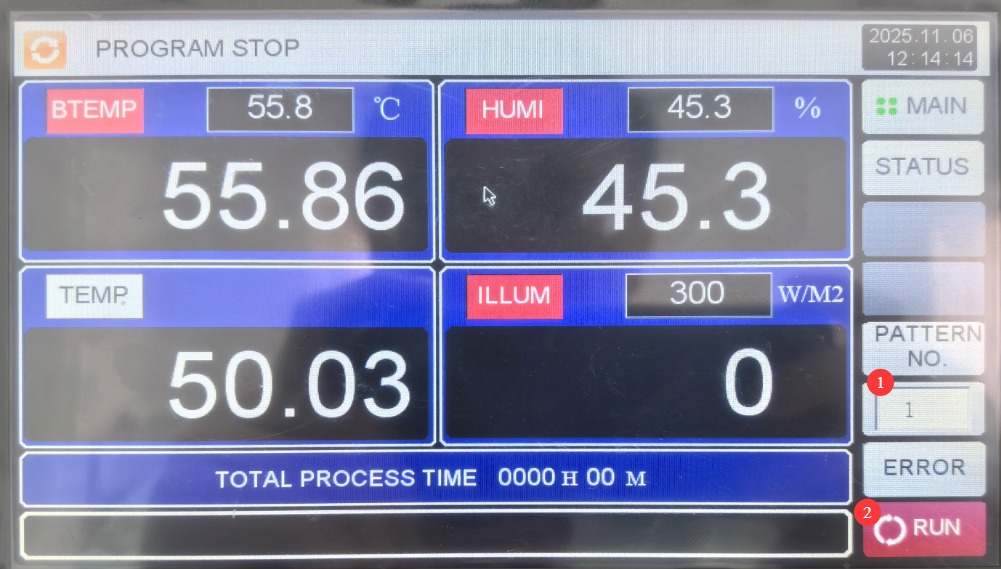
① Go to the “Monitoring Screen” and enter the program group number you want to run; ② Click “Run.”
Gambar 22
4.6 Pelaksanaan dan Pemantauan Program
4.6.1 Pemantauan Kesalahan Secara Real-Time
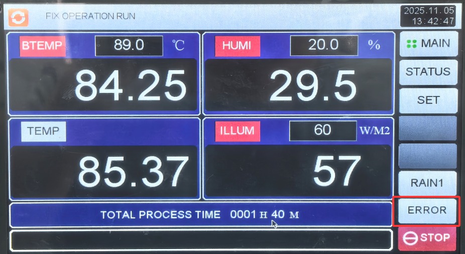
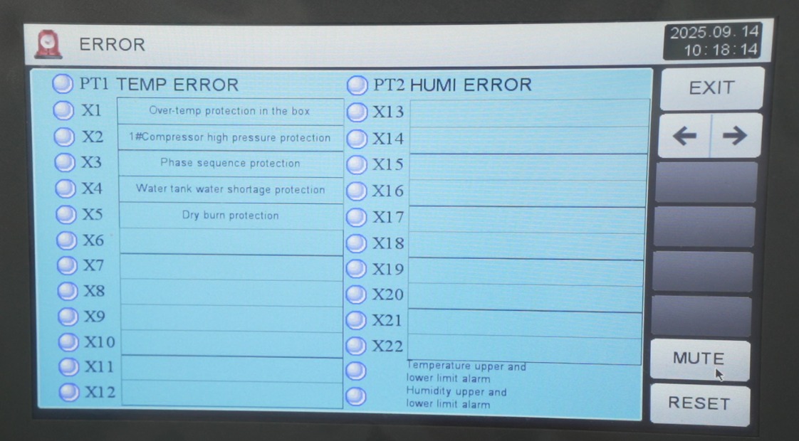
If a malfunction occurs during operation, the device will automatically redirect to the error page. Please refer to Chapter 7 for troubleshooting instructions.
Gambar 22.1
Gambar 22.2
4.6.2 Melihat Kurva Uji
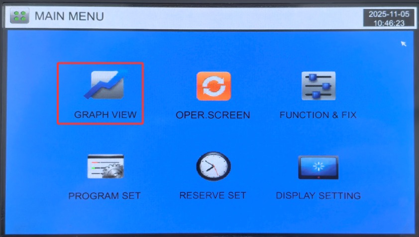
Go to the “Curve Display” screen to view current and historical test curves and export them to a USB drive.
Gambar 23
5. Prosedur Pasca-Ujian
5.1 Equipment Cooling
After the test is complete, the equipment will automatically display the message “Test Complete.” Do not turn off the power immediately; leave it on for 10 minutes (this is a delayed cooling protection feature for the xenon lamp to prevent damage to the lamp tube caused by rapid cooling after high temperatures).
During the cooling process, observe the instrument display: the xenon lamp indicator changes from “on” to “off,” the fan continues to run, and the temperature gradually drops to room temperature (≤40°C).
5.2 Shutting Down the Equipment
Once cooling is complete, press the power switch button on the control panel to turn off the instrument’s power; then turn off the power circuit breaker on the back of the device (flip it down to “OFF”); finally, turn off the external power switch.
If the device will not be used for an extended period (more than one week), unplug the power cord, open the drain valve on the water tank, and drain any remaining water from the tank (to prevent bacterial growth or limescale buildup).
5.3 Cleaning the Interior of the Cabinet
Once the temperature inside the chamber has dropped to room temperature, open the chamber door, remove the test specimen, and record its condition.
Wipe down the interior of the chamber with a dry cloth (paying special attention to the drip tray and air outlet), and thoroughly dry any remaining water to prevent humidity deviations during the next test. If there are any stains left on the test specimens, clean them with a dry cloth dipped in a small amount of alcohol (use this only on the stainless steel interior), then dry them with a dry cloth.
Check the gauze on the humidity probe: If it is dirty or has hardened, replace it with a new piece of gauze; if it is clean, it can be saved for the next use.
Close the cabinet door and cover the equipment with a dust cover (if available) to prevent dust from entering.
6. Pemeliharaan dan Perawatan Peralatan Harian
| Siklus Pemeliharaan | Proyek Pemeliharaan | Persyaratan Pemeliharaan |
| Before each test / As needed | Humidity Sensor Gauze | Check for hardening or dirt; replace immediately if any abnormalities are found. |
| Water Level (Water Tank, Humidifier) | If the water level in the tank is ≥ “MIN,” the water level in the humidifier covers the humidification tube. | |
| Over-Temperature Protector | Check the setpoint (test temperature + 20°C) to ensure there is no deviation. | |
| Cleaning the Inner Pot | Wipe away dust and standing water from the inner pot, leaving no stains behind | |
| Pompa air | Before starting operation, listen for any unusual noises; the absence of noise is considered normal. | |
| Cleaning the Humidifier Tubes | Check the humidifier tube for scale; if any is present, clean it with a citric acid solution. | |
| Bulanan | Door Weatherstripping | Check for signs of wear and tear or air leaks (use your hand to feel for airflow around the door seal). |
| Deep Cleaning of the Humidifier Tubes | Remove the humidifier tube and use a soft-bristled brush to clean limescale from the inside walls. | |
| Setiap tiga bulan | Calibration of Over-Temperature Protectors | Calibrated using a standard thermometer; setpoint deviation ≤ 1°C |
| Cleaning the Inside of the Water Tank | Empty the tank, rinse the inside with clean water, wipe it dry, and refill it with water. | |
| Inspeksi Sistem Air | Check that the drainpipe is clear and free of blockages (you can test this by running clean water through it). | |
| Setiap enam bulan | Cleaning the Electrical Control Cabinet | After turning off the power, use compressed air to blow out the dust from inside the cabinet; ensure there are no foreign objects. |
| Cleaning the Housing | Wipe the casing with a dry cloth to remove dust and grease. |
7. Pemecahan Masalah dan Penyelesaian Masalah Umum
7.1 Program Errors
| Kode Pemecahan Masalah | Kemungkinan penyebab | Prosedur |
| X1 Over-Temperature Protection | 1. The set temperature exceeds the upper limit | 1. Reset the over-temperature protection dial by turning it; 2. Reset the temperature |
| Kompresor X2 No. 1 Tekanan Berlebih | 1. Poor heat dissipation from the condenser; 2. Excessive refrigerant; 3. Water-cooled unit not turned on; 4. Blockage in the piping system | 1. Air-cooled: Clean dust from the condenser; Water-cooled: Turn on the water-cooling unit; 2. Check the refrigerant pressure and purge any excess; 3. Use a multifunction gauge to check the suction pressure, and replace the capillary tube and dry filter. |
| X3 Phase Sequence Error | 1. Check whether the phase sequence matches the wiring inside the enclosure. | 1. Swap the positions of the first and third live wires. |
| X4 Low Coolant Level | Low Water Level in the Tank | Check the water lines to ensure the water supply is working properly, or add water manually. |
| X5 Dry-Burn Protection | 1. Water shortage in the tank 2. Low water level in the boiler 3. Clogged water pipe | Check the water lines to ensure the humidification system is receiving a normal water supply. |
7.2 Control-Related Faults
| Gejala Kesalahan | Kemungkinan penyebab | Prosedur |
| Controller buttons do not work / Touchscreen is unresponsive | 1. Touchscreen calibration error; 2. Internal contact issues with the buttons; 3. Controller software malfunction. | 1. Go to [Display Settings] → [Touchscreen Calibration], turn off the power, press the touchscreen, and then turn the power back on to enter the calibration page and recalibrate; 2. If calibration does not resolve the issue, contact the manufacturer to replace the buttons or the touchscreen; 3. Restart the device; if the problem persists, the manufacturer will need to reflash the firmware. |
| The controller has no display | 1. The power is not turned on; 2. The instrument’s power module is damaged; 3. The circuit board is faulty. | 1. Check whether the main circuit breaker and the heating circuit breaker are closed, and whether the power cord is securely plugged in; 2. If there is still no display after turning on the power, contact the manufacturer to replace the power module; 3. If the module is functioning properly, the circuit board needs to be replaced. |
| Communication Error (PLC Not Responding) | 1. The communication cable between the touchscreen and the PLC is loose; 2. The communication cable is broken; 3. The PLC module is malfunctioning. | 1. Turn off the power and reconnect the communication cable (RS-485 cable) securely; 2. Check the communication cable for breaks; if any are found, replace it; 3. If the wiring is correct, contact the manufacturer to have the PLC module inspected. |
7.3 Operational Faults
| Gejala Kegagalan | Kemungkinan penyebab | Prosedur |
| Unusual noises during equipment operation | 1. Loose fan blades (interior fan or condenser fan); 2. Unit not level (level deviation > 1°); 3. Friction between the fan and the air duct. | 1. After shutting down the unit, use a wrench to tighten the fan blade mounting screws; 2. Level the unit using a level, and place shims under the casters to ensure it is level; 3. Adjust the position of the duct to increase the clearance between the fan and the duct to prevent friction. |
| Trouble with the Box Door / Hard to Open | 1. Abnormal pressure inside the cabinet (high pressure in high-temperature, high-humidity conditions, making it difficult to close; low pressure in low-temperature conditions, making it difficult to open); 2. The door sags (loose hinges); 3. Foreign objects are stuck in the door hinges. | 1. Difficulty closing: Wait for the pressure to equalize before closing the door; difficulty opening: Open the door slowly to allow air to enter and equalize the pressure (this is normal);2. Tighten the door hinge screws and adjust the door position to ensure proper alignment; 3. Remove any foreign objects (such as dust or sample residue) from the hinges. |
| The device won’t start | 1. Missing phase or insufficient voltage in the power supply; 2. Over-temperature protector triggered (setpoint too low); 3. Low water level alarm not cleared; 4. Door not closed properly (door switch not triggered). | 1. Check the power supply phase sequence and voltage (AC 380 V ± 5%); 2. Reset the over-temperature protector (press the reset button on the protector) and set the new value (test temperature + 20 °C);3. Refill the water tank with purified water to the MAX water level to clear the alarm; 4. Close the chamber door again and ensure the door switch is triggered (the display shows “Door Closed”). |
| The temperature won’t go up / won’t go down | Cannot heat up: 1. The heating circuit breaker is not closed; 2. The heating element is damaged; 3. The fan is not running (poor hot air circulation); Cannot cool down: 1. The chiller has not started (the chiller circuit breaker is not closed);2. Refrigerant leak; 3. Ambient temperature too high (>25℃). | Failure to cool: 1. Close the heating circuit breaker; 2. Use a multimeter to check the resistance of the heating element (a normal reading indicates it is functioning; infinite resistance indicates a failure and requires replacement);3. Check the fan power supply; replace the fan (if it is not spinning); Fails to cool: 1. Close the chiller circuit breaker; 2. Contact the manufacturer to check the refrigerant pressure; if there is a leak, repair it and recharge the refrigerant; 3. Turn on the air conditioner to lower the ambient temperature to ≤25°C. |
| The air conditioner does not dehumidify when it’s cold. | 1. Frost buildup on the evaporator (caused by excessive humidity); 2. The dehumidifier fan is not running; 3. The humidity sensor is malfunctioning. | 1. Shut down the unit and restart it after the evaporator has defrosted (or activate the defrost function, if available); 2. Check the fan wiring and replace the fan (if it is not rotating); 3. Replace the humidity sensor and calibrate the humidity display. |
| The spray flow is not smooth / There is a leak | Water flow is not smooth: 1. Clogged nozzle (blocked by debris); 2. Low water pressure due to a leak in the water pipe; Leak: 1. Cracked nozzle; 2. Loose water pipe connection. | Water flow is not smooth: 1. Remove the nozzle and rinse it with clean water (or use a fine needle to clear the nozzle holes);2. Check the hose connection; tighten it or replace the O-ring; Leak: 1. Replace the cracked nozzle; 2. Tighten the hose connection; if the leak persists, replace the hose. |
| The xenon headlight won’t turn on | 1. The xenon lamp tube is damaged; 2. The xenon lamp power supply module is malfunctioning; 3. The startup interval is less than 5 minutes (protective mechanism). | 1. Turn off the power and replace the xenon lamp tube (this must be performed by a manufacturer-authorized technician to avoid electric shock); 2. Check the output voltage of the power module and replace the module (if there is no output); 3. Wait at least 5 minutes, then restart the xenon lamp. |
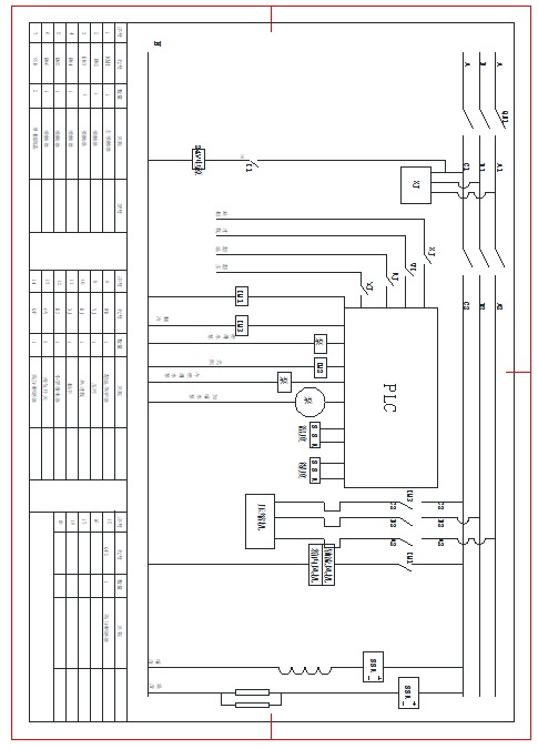
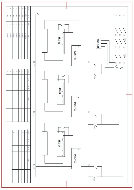
Lampiran: Diagram Rangkaian