
 Inggris
 中文简体
中文简体 Русский
 Español
 Português
 Türkçe
 العربية
 Deutsch
 Polski
 Italiano
 Français
 한국어
한국어 ไทย
ไทย Tiếng Việt
 日本語
日本語





























Alat Ukur Hipot AC / DC
Pengguna manual
berlaku LISUN Model: WB2681A
1. Membuka Kemasan dan Mengenal Perangkat Secara Dasar
1.1 Spesifikasi Teknis Utama
| Parameter Teknis | Note |
| Tegangan Isolasi | DC 250 V, DC 500 V, DC 1000 V (three settings available) |
| Turn-on Voltage Range | ±10% @ rated voltage |
| Perlawanan Isolasi | 0–1999 MΩ |
| Waktu Tes | 1–99 seconds or manual control |
1.2 Membuka Kemasan dan Memeriksa Aksesoris
1.2.1 Membuka Kemasan dan Pemeriksaan Visual
When unpacking the device, handle it gently to avoid scratching the exterior casing with sharp tools. After unpacking, first inspect the exterior of the device to ensure there is no visible deformation or dents, and that the buttons are not damaged or loose. If you notice any abnormalities with the device or its accessories, do not turn it on. Please contact us immediately.
1.2.2 Unit Utama dan Aksesoris
Pembawa acara: 1 WB2681A tuan rumah.
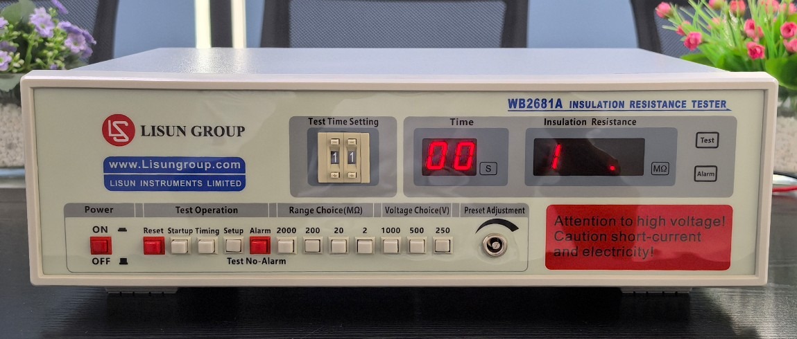
Gambar 1
Komponen utamanya adalah sebagai berikut:
| Jumlah | Note |
| ① | Kabel Listrik |
| ② | Test Object Connection Cable |
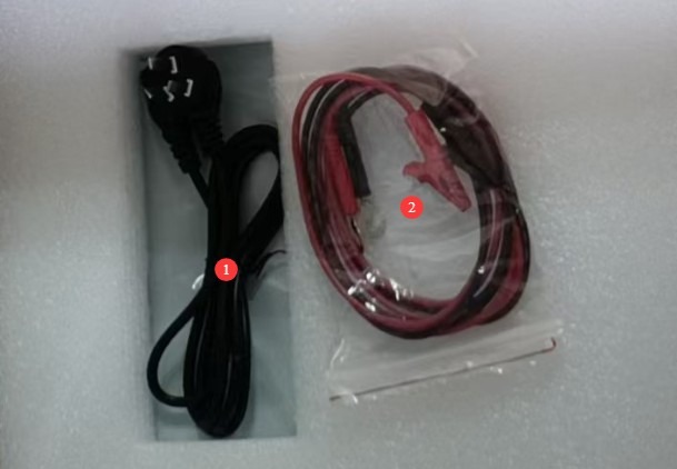
Gambar 2
Tautan unduhan untuk manual pengguna digital, perangkat lunak, kartu garansi, dan materi lainnya telah dikirim melalui email. Silakan unduh sesegera mungkin. Jika Anda melewatkan email tersebut, Anda dapat menghubungi kami untuk meminta tautan unduhan lagi.
2. Tindakan Pencegahan Keamanan
2.1 Keamanan Listrik
2.1.1 Persyaratan Catu Daya
Use a single-phase AC 220V ±10%, 50/60 Hz three-prong outlet; the ground prong must be connected to earth.
2.1.2 Persyaratan Pembumian
The instrument ground wire is reliably connected to the protective grounding conductor, and the protective grounding resistance is ≤4 Ω;
Jangan menghubungkan terminal keluaran ke sumber daya AC secara langsung untuk mencegah casing teraliri listrik.
2.2 Keselamatan Lingkungan
2.2.1 Persyaratan Suhu dan Kelembaban
Avoid using the device in environments where humidity exceeds 70% (without condensation) or temperatures fall outside the range of 0–35°C. The optimal operating temperature is 25±2°C.
2.2.2 Kontraindikasi Lingkungan
Lingkungan dengan medan magnet yang kuat dan medan listrik yang kuat;
Lingkungan yang mengandung gas atau cairan korosif;
Areas with flammable and explosive dust or hazardous materials;
Lingkungan dengan banyak debu, suhu dan kelembapan tinggi, serta sinar matahari langsung.
2.3 Keselamatan Operasional
The test circuit of the equipment can generate an output voltage of up to 1000 V DC. Once testing begins, do not touch the test circuit, the device under test, or the metal ends of the test leads with your hands. Do not short-circuit the test leads to prevent high-voltage electric shock;
It is strictly prohibited to perform insulation resistance tests on live circuits, equipment, or components; before testing, ensure that the test subject is completely de-energized and has been properly discharged;
Spesimen uji harus diletakkan di atas alas isolasi karet;
Operator wajib mengenakan sarung tangan karet berinsulasi;
Operator harus memiliki tangan yang kering dan tidak boleh mengenakan perhiasan logam apa pun; makan atau minum dilarang selama pengujian untuk mencegah kecelakaan yang disebabkan oleh sengatan listrik;
Sebelum mengganti objek uji, Anda harus terlebih dahulu menghentikan pengujian dan memverifikasi bahwa tegangan keluaran perangkat adalah 0;
When multiple people are involved, clearly define roles and responsibilities, and confirm with each other before starting the test to avoid errors.
2.4 Lainnya
Untuk hal-hal yang tidak tercakup dalam panduan ini, harap berhati-hati atau hubungi kami.
3. Gambaran Umum Peralatan dan Pengkabelan
3.1 Pengenalan Panel Depan Peralatan
| Jumlah | Note |
| ① | Saklar daya |
| ② | Test time setting: two-digit dial code; test times can be set from 1 to 99 seconds; used in conjunction with a timer switch |
| ③ | Tampilan waktu pengujian, dalam detik. Catatan: Hanya tersedia saat sakelar pengatur waktu diaktifkan. |
| ④ | “The insulation resistance display shows the insulation resistance value of the test object during testing and the lower limit of the alarm resistance during setup. If the selected range is too small, an overflow indicator ‘1’ appears. If ‘1’ is still displayed at the maximum range, it indicates that the test object is open-circuited or that its resistance exceeds the device’s measurement range.” |
| ⑤ | Test Status Indicator: Test: Testing in progress; Alarm: Insulation resistance below threshold + buzzer alarm (long beep) |
| ⑥ | Reset button: Press to clear the alarm, end the test, and return the device to standby mode. |
| ⑦ | Tekan tombol Mulai untuk memulai pengujian; lampu indikator pengujian akan menyala. |
| ⑧ | Timer switch: Press to enable the timer; release to disable the timer. |
| ⑨ | Preset/Test Switch: Press to enter Preset mode and set the lower limit of the alarm resistance; push out to enter Test mode, where you can perform a formal test. |
| ⑩ | Alarm button: Press to enable the alarm (an alarm sounds when the insulation resistance falls below the lower limit); release to disable the alarm. |
| ⑪ | Range selection button, with four selectable ranges: 2 MΩ, 20 MΩ, 200 MΩ, and 2000 MΩ |
| 1 | Test voltage selection button: Three settings available—DC 250 V, 500 V, and 1000 V |
| ⑬ | Resistance Threshold Adjustment Knob: In the default setting, this knob adjusts the lower limit of the alarm resistance, in MΩ. |
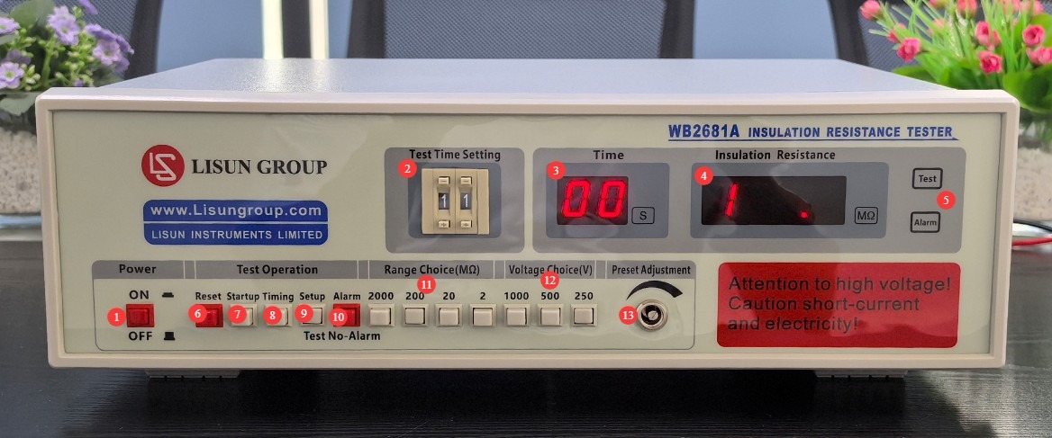
Gambar 3
3.2 Introduction to the Equipment Back Panel
| Jumlah | Note |
| ① | Power cord receptacle, with built-in fuse |
| ② | Connect the test leads to the resistor under test: use the red lead to connect to the high-voltage end of the device, and use the black lead to connect to the low-voltage end or ground of the device. |
| ③ | Ground terminal; connect to the shielding layer of the device under test (if any) |
| ④ | PLC output interface (expanded functionality) allows the device to be integrated with other equipment to form an interlocked system. “Start” and “Reset” are external passive normally open contact inputs, while “Test” and “Alarm” are passive normally open contact outputs from the device. |
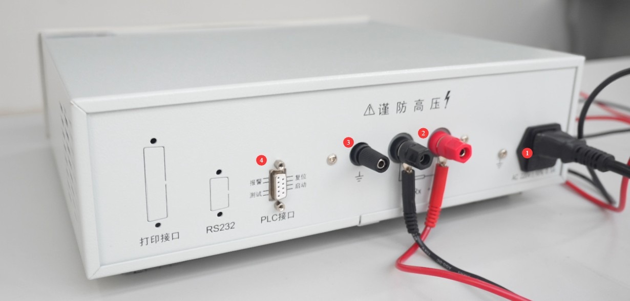
Gambar 4
4. Persiapan Sebelum Ujian
4.1 Equipment Warm-up
Turn on the device. At this point, the insulation resistance display window will show the overflow indicator “1,” and the test time display window will show “00.” Allow the device to warm up under no-load conditions for 15 minutes before proceeding with subsequent operations to ensure that the internal components are operating stably.
4.2 Persiapan Spesimen Uji
4.2.1 Power Interruption and Discharge
Ensure that the power supply to the device under test is completely disconnected. For devices under test that contain energy-storage components such as capacitors and inductors, perform a thorough short-circuit discharge to prevent residual voltage from damaging the equipment or causing electric shock.
4.2.2 Surface Cleaning and Treatment
Wipe away any dust, oil, or water from the test area of the test object to ensure that its surface is dry and clean. This prevents surface contaminants from causing low insulation resistance readings, which could lead to incorrect results.
4.2.3 Menghubungkan Objek Uji
Identify the high-voltage end and low-voltage end/ground end of the device under test, and determine whether there are any polarity requirements for the connections; check that the device under test has no physical damage or broken wires and is in a normal, ready-to-test condition; make the connections as described in Section 3.2.
5. Prosedur Uji
5.1 Basic Test Parameter Settings
5.1.1 Selection of Test Voltage
Based on the type of test object and the standard requirements (see Appendix), press the test voltage selection button on the front panel to select the appropriate setting for 250 V, 500 V, or 1000 V DC, ensuring that the voltage setting matches the requirements for the test object.
5.1.2 Selection of Measurement Range
Based on the estimated insulation resistance value of the test object, press the range selection button on the front panel to select the appropriate range (2 MΩ, 20 MΩ, 200 MΩ, or 2000 MΩ). If no estimated value is available, select the highest range first, then adjust it based on the test results.
5.2 Setting the Lower Limit for the Alarm Resistance (Optional)
Press the Preset/Test switch on the front panel. The device will then enter the alarm value setting mode, and the insulation resistance display window will show the set value.
Press the start button; the test indicator light will turn on, simulating the test condition. Use a small screwdriver to slowly adjust the resistance threshold knob and observe the changes in the value displayed in the insulation resistance window until the displayed value matches the lower limit of the alarm resistance specified by the standard or test requirements.
After calibration is complete, press the Reset button to pop up the Preset/Test switch, and the device will return to test standby mode; press the Alarm button to enable the alarm function.
5.3 Timed Test Parameter Settings (Optional)
Press the timer switch on the front panel to enter timed test mode; the test time display window will enter the set value state.
Turn the test time setting DIP switch (two-position) to set the test duration to a value between 1 and 99 seconds, as required by the standard or test specifications. Observe the value displayed in the test time window to confirm that it matches the set value.
If scheduled testing is not required, simply keep the timer switch in the “on” position; the test duration can then be controlled manually.
5.4 Uji Startup
Press the Start button on the front panel; the test indicator light will illuminate, high voltage will be output from the device’s test terminal, and the device will officially enter test mode:
Timed Mode: The test time display window begins a countdown, and the insulation resistance display window shows the insulation resistance value of the test object in real time; Manual Mode: The test time display window remains at “00,” and the insulation resistance display window shows the insulation resistance value of the test object in real time.
Warning: Do not touch the test object, test leads, or equipment terminals during testing to prevent electric shock from high voltage.
5.5 Ending the Test
5.5.1 Manual Reset Termination
Whether in timed or manual mode, if you need to terminate the test early, press the reset button on the front panel. The test indicator light will turn off, the high-voltage output will stop, the device will return to standby mode, and any alarms (if present) will be cleared simultaneously.
5.5.2 Automatic Alarm Termination
If the alarm function is enabled, when the insulation resistance of the test object falls below the preset lower limit, the alarm indicator light will illuminate, the device will emit a long audible alarm, and the test will automatically terminate while the high-voltage output stops.
5.5.3 Automatic Termination Upon Timer Expiration
In timed test mode, when the test timer counts down to “00,” the device automatically terminates the test, the test indicator turns off, and the high-voltage output stops. If the insulation resistance of the test object meets the requirements, no alarm will sound.
5.6 Interpretasi Hasil Tes
5.6.1 Penentuan Kesesuaian
Throughout the entire test, if the value displayed in the insulation resistance window remains stable and the insulation resistance of the test object is ≥ the standard requirement or the set lower alarm limit, the test object is deemed to have passed.
5.6.2 Penentuan Ketidaksesuaian
During testing, if the device triggers an alarm, the alarm indicator lights up, and the value displayed in the insulation resistance window is less than the set lower alarm limit, the test result is deemed unsatisfactory.
5.6.3 Determining Abnormalities in Range/Voltage Settings
After the test begins, the device emits an intermittent beep. The value displayed in the insulation resistance window is invalid, indicating a mismatch between the voltage range and the measurement range. Reset the device, adjust the ranges according to the standard requirements, and then retest;
After the test starts, if the insulation resistance display window shows the overflow indicator “1,” it means the range selected is too small. Reset the device, select a higher range, and retest.
6. Pemeliharaan dan Perawatan Peralatan Harian
6.1 Perawatan Rutin
Before turning on the power, inspect the equipment to ensure it is clean and undamaged, that the cables show no signs of aging or breakage, and that the connectors are secure; Check that the test object’s connecting cables are free of oxidation or burn marks; if any are present, wipe them with a specialized contact cleaner, and contact us to replace parts if necessary; after testing is complete, disconnect the power and wipe the device’s surface and the test area with an antistatic, dry cloth.
6.2 Penyimpanan Jangka Panjang
Saat perangkat tidak digunakan dalam jangka waktu lama, simpan di tempat yang kering dan berventilasi baik, jauhkan dari kelembapan dan sinar matahari langsung; lepaskan semua kabel, simpan aksesori secara terpisah, dan tutupi perangkat dengan kain anti debu; nyalakan perangkat selama 30 menit setiap bulan untuk mencegah kerusakan komponen elektronik internal.
7. Pemecahan Masalah dan Penyelesaian Masalah Umum
| Gejala Kesalahan | Kemungkinan penyebab | Prosedur |
| Perangkat tidak mau menyala | Kabel daya tidak terpasang dengan benar; sekring putus. | Check the power cord connections; check the fuse in the device’s power input port. If it is blown, replace it with a 5A fuse of the same model. |
| After turning on the computer, the screen flickers and the keys don’t respond. | Tegangan Catu Daya Tidak Stabil | Use a multimeter to measure the supply voltage and verify that it falls within the range of AC 220 V ± 10%. If the voltage is unstable, install a voltage regulator. |
| After the test starts, the device emits an intermittent beep. | The range setting is too high | Please reset the device, select a lower gear, and try again. |
| After the test started, the insulation resistance display window showed the overflow indicator “1.” | The selected range is too small | Reset the device, then select the high range and retest. If “1” is still displayed when the maximum range is selected, this indicates that the test circuit is open or that the resistance of the device under test is too high. |
| The values in the display window are fluctuating erratically | The operating environment may be subject to interference from strong magnetic fields or strong electric fields. | Keep away from environments with strong magnetic fields or strong electric fields. |
| Test results do not match the alarm status (test results are normal but an alarm is triggered; test results are abnormal but no alarm is triggered) | Incorrect sequence of operations for selecting the measurement range and setting thresholds | Please refer to Chapter 5. Be sure to select the measurement range before setting the threshold; otherwise, the threshold values will be unavailable. |
Appendix A: Insulation Resistance Test Requirements in Relevant Standards
| Nomor Standar | By Type of Electronic Product/System | Recommended Test Voltage (DC) | Insulation Resistance Requirements | Durasi Tes | Other Testing Requirements |
| GB 4706.1-2024/IEC 60335-1:2023 | Household and Similar Electrical Appliances | 250 V / 500 V | Basic insulation: ≥2 MΩ; Reinforced insulation/double insulation: ≥7 MΩ | ≥1 detik | Before testing, the test item must be at its normal operating temperature, and tests must be conducted on live parts and accessible metal parts. |
| GB 7000.1-2023/IEC 60598-1:2024 | Light Fixtures and Lighting Equipment | Basic insulation: ≥2 MΩ; Reinforced insulation/double insulation: ≥5 MΩ; Protective insulation: ≥2 MΩ | Tests on live parts of luminaires in relation to their enclosures and insulating parts; luminaires used in damp environments require stricter testing requirements. | ||
| GB 4943.1-2022/IEC 60950-1:2023 | Information Technology Equipment, Audio and Video Equipment | Basic insulation: ≥2 MΩ; reinforced insulation/double insulation: ≥4 MΩ | The test site is between the live parts and the protective grounding, or between the metal substrate and accessible non-metallic parts; the test is conducted with the equipment in a no-load state. | ||
| GB 9706.1-2020/IEC 60601-1:2020 | Peralatan Listrik Medis | 500 V / 1000 V | Basic insulation: ≥2 MΩ; protective insulation: ≥5 MΩ; reinforced insulation: ≥10 MΩ | ≥5 detik | Medical devices must be tested separately under no-load and loaded conditions; insulation testing requirements are stricter for patient-contact parts, and insulation breakdown is prohibited. |
| GB/T 50150-2016/IEC 61557-1:2021 | Electrical equipment used in electrical installation projects (Voltage Transformers, motors, cables, switches, etc.) | Motors/Voltage Transformers: ≥0.5 MΩ (low voltage), ≥1 MΩ (high voltage); Cables: ≥1 MΩ/1 kV; Power Distribution Equipment: ≥2 MΩ | ≥10 detik | The equipment must be fully discharged before testing. For high-voltage electrical equipment, a test voltage of 1000 V should be used whenever possible, and the measured values must be adjusted to account for the effects of ambient humidity. |