
 Inggris
 中文简体
中文简体 Русский
 Español
 Português
 Türkçe
 العربية
 Deutsch
 Polski
 Italiano
 Français
 한국어
한국어 ไทย
ไทย Tiếng Việt
 日本語
日本語





























Penguji Tegangan Tahan AC
Pengguna manual
berlaku LISUN Model: WB2672A
1. Pemahaman Dasar tentang Peralatan
1.1 Spesifikasi Teknis Utama
| Model/Spesifikasi | Rentang Tegangan Uji | Rincian Rentang Arus | Kapasitas Transformator Tegangan | Durasi Tes | Ketepatan |
| WB2672A | 0–10 kV (AC) | AC: 0–20 mA | 200 VA | 1–999 detik | ± 5% |
1.2 Verifikasi Konfigurasi Peralatan
1.2.1 Membongkar
When unpacking the device, handle it gently to avoid scratching the outer casing with sharp tools. After unpacking, first inspect the exterior of the device to ensure there are no obvious deformations or dents, and that the buttons are not damaged or loose. If you notice any abnormalities with the device or its accessories, do not turn it on. Please contact us immediately.
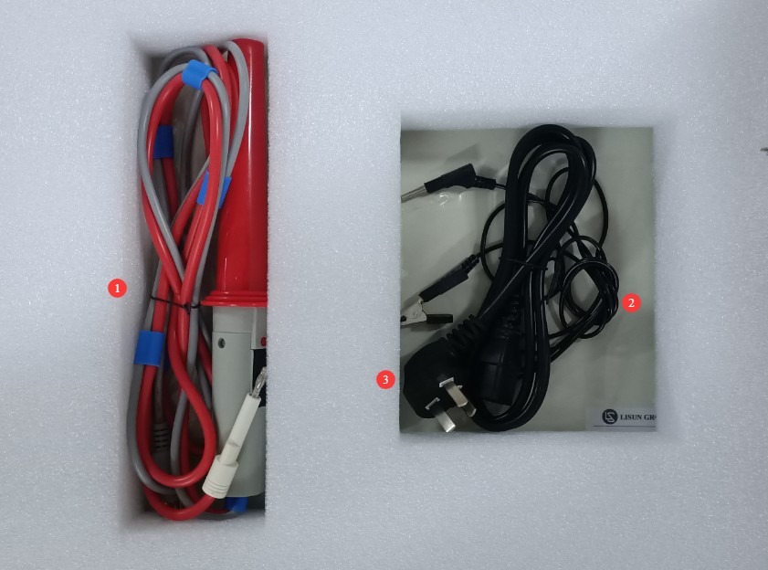
1.2.2 Unit Utama dan Aksesoris
Pembawa acara: 1 WB2672A tuan rumah.
Komponen utamanya adalah sebagai berikut:
| Jumlah | Note |
| ① | High-voltage rod, including a high-voltage rod connection cable and a remote control cable; the handheld end of the high-voltage rod includes control buttons |
| ② | Penjepit Pembumian |
| ③ | Kabel Listrik |
1.2.3 Mengunduh Dokumen Elektronik
We have already sent the download links for the digital user manual, warranty card, and other documents via email at the time of shipment. Please download them as soon as possible. If you missed the email, you can contact us to request the download links again.
2. Tindakan Pencegahan Keamanan
2.1 Keamanan Listrik
Persyaratan Daya 2.1.1
Use a single-phase AC 220 V ±10%, 50/60 Hz three-prong outlet; the ground prong must be connected to earth.
2.1.2 Persyaratan Pembumian
Kabel ground instrumen terhubung dengan andal ke kabel ground pelindung, dan resistansi ground pelindung ≤4 Ω;
Do not short-circuit the output terminal to the AC power source to prevent the housing from becoming energized.
2.2 Keselamatan Lingkungan
2.2.1 Persyaratan Suhu dan Kelembaban
Hindari penggunaan perangkat di lingkungan dengan kelembapan melebihi 70% (tanpa kondensasi) atau di mana suhu berada di luar kisaran 0–35°C. Suhu pengoperasian optimal adalah 25±2°C.
2.2.2 Kontraindikasi Lingkungan
Lingkungan dengan medan magnet yang kuat dan medan listrik yang kuat;
Lingkungan yang mengandung gas atau cairan korosif;
Area dengan debu yang mudah terbakar dan meledak, serta area yang mengandung bahan berbahaya;
Lingkungan dengan banyak debu, suhu dan kelembapan tinggi, serta sinar matahari langsung.
2.3 Keselamatan Operasional
During testing, the housing of the test object is live; do not touch it with your bare hands under any circumstances;
Spesimen uji harus diletakkan di atas alas isolasi karet;
Operator wajib mengenakan sarung tangan karet berinsulasi;
Never short-circuit the high-voltage output (high-voltage probe) directly to the ground terminal (ground clamp), as this may cause the internal Voltage Transformer to burn out;
Operator harus memiliki tangan yang kering dan tidak boleh mengenakan perhiasan logam apa pun; makan atau minum dilarang selama pengujian untuk mencegah kecelakaan yang disebabkan oleh sengatan listrik;
Sebelum mengganti objek uji, Anda harus terlebih dahulu menghentikan pengujian dan memverifikasi bahwa tegangan keluaran perangkat adalah 0;
Jika melibatkan beberapa orang, tetapkan peran dan tanggung jawab dengan jelas, dan konfirmasikan satu sama lain sebelum memulai pengujian untuk menghindari kesalahan.
2.4 Lainnya
Untuk hal-hal yang tidak tercakup dalam panduan ini, harap berhati-hati atau hubungi kami.
Ikhtisar Peralatan
3.1 Pengenalan Panel Depan Peralatan
| Jumlah | Note |
| ① | Saklar daya |
| ② | High-voltage output connector, for connecting to the live parts of the device under test |
| ③ | Stopkontak yang dikendalikan dari jarak jauh; kabel kendali jarak jauh terhubung ke batang tegangan tinggi. |
| ④ | Hubungkan penjepit pembumian; gunakan ujung colokan pisang untuk menghubungkan ke instrumen, dan ujung penjepit untuk menghubungkan ke perangkat yang sedang diuji. |
| ⑤ | Test time display window; can be set from 1 to 999 seconds |
| ⑥ | Jendela tampilan arus bocor: Menampilkan ambang batas alarm dalam mode siaga dan arus bocor waktu nyata dalam mode uji, dalam mA. |
| ⑦ | Jendela tampilan tegangan keluaran, menunjukkan nilai tegangan keluaran tinggi saat ini dalam kV. |
| ⑧ | Indikator Status Pengujian: TE: Sedang diuji; NG: Arus bocor melebihi ambang batas + bel berbunyi |
| ⑨ | Tombol pengaturan |
| ⑩ | Arrow keys: Use to adjust the number of digits displayed when setting parameters |
| ⑪ | Titik desimal |
| 1 | Value adjustment keys: Use these to adjust the numerical values when setting parameters. |
| ⑬ | Tombol konfirmasi |
| ⑭ | Tombol pengatur tegangan keluaran: Putar searah jarum jam untuk meningkatkan tegangan keluaran; putar berlawanan arah jarum jam untuk menurunkannya. |
| 3 | Tekan tombol Mulai untuk memulai pengujian; lampu indikator pengujian akan menyala. |
| 5 | Tombol reset: memutus tegangan keluaran, menghentikan pengujian, dan menghapus alarm. |
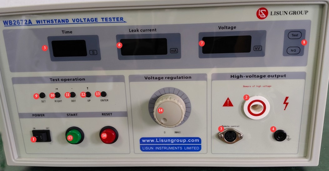
Note: Once the remote control cable is connected, the power and reset buttons on the front panel of the device will not function.
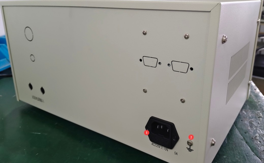
3.2 Introduction to the Equipment Back Panel
| Jumlah | Note |
| ① | Soket kabel daya, untuk menghubungkan perangkat ke sumber daya yang sesuai. |
| ② | Terminal pembumian pelindung: Terhubung singkat secara internal ke terminal pembumian kabel daya. Jika kabel daya sudah menyediakan pembumian pelindung yang memadai, terminal ini tidak perlu disambungkan. |
4. Persiapan Sebelum Pengujian
4.1 Menghidupkan Peralatan
Plug the power cord into a standard three-prong outlet, press the power switch, and the instrument’s display will light up. The TE and NG indicator lights will both be off, and the leakage current and voltage displays will show 0. If there are no abnormal audible or visual alarms, this indicates that the device’s power-on self-test was successful. Use the AC/DC test mode selector switch on the main unit as needed.
4.2 Persiapan Spesimen Uji
Selubung benda uji harus bersih dan bebas dari minyak; letakkan di tengah alas isolasi, jauh dari permukaan logam benda kerja.
5. Prosedur Uji
5.1 Pengaturan Parameter Uji
All parameter presets must be completed by following the steps below, with the high-voltage rod, remote control cable, and grounding clamps unplugged.
| petunjuk | Note |
| ① | Press the Set button; the numbers in the test time display window will flash. Set the test duration using the arrow keys and the value adjustment keys. If you need to manually control the test duration, set it to 0. Once set, press the Set button again to proceed to the next parameter. If you do not need to set any other parameters, press the Confirm button to exit. |
| ② | Continue to set the next parameter. The number in the leakage current window will flash. Set the upper limit for the leakage current using the arrow keys, the decimal point key, and the value adjustment keys. Once set, press the “Set” key to proceed to the next parameter. If no other parameters need to be set, press the “Confirm” key to exit. |
| ③ | Continue to the next parameter to set the lower limit for leakage current. The factory default is 0, and this setting generally does not need to be adjusted. Press the “Set” button to proceed to the next parameter. If you do not need to set any other parameters, press the “Confirm” button to exit. |
| ④ | Continue to set the next parameter. The leakage current range automatically switches based on the upper limit value set for leakage current, with two ranges available: 2 mA and 20 mA. Press the “Set” button to proceed to the next parameter. If no other parameters need to be set, press the “Confirm” button to exit. |
| ⑤ | Continue to set the next parameter: buzzer alarm. “ON” enables it and “OFF” disables it; use the adjustment keys to toggle between settings. Once set, press the “Set” key to proceed to the next parameter. If you do not need to set any other parameters, press the “Confirm” key to exit. |
| ⑥ | Continue to configure the next parameter. The communication address and baud rate are communication-related parameters; since this device does not have communication capabilities, these do not need to be set. Screen brightness ranges from 1 (dimmest) to 5 (brightest). After configuring these settings, press the “Set” button to proceed to the next parameter. If no other parameters need to be set, press the “Confirm” button to exit. |
| ⑦ | Output Voltage Setting: Press the Start button and observe the value displayed in the output voltage display window. Use the output voltage adjustment knob to set it to the required standard value. Once adjusted, press the Reset button. |
Catatan: Untuk pengujian dengan laju kenaikan tegangan yang ditentukan, jangan mengatur tegangan terlebih dahulu; cukup putar kenop ke 0. Setelah pengujian resmi dimulai, putar kenop secara perlahan untuk menyesuaikan tegangan keluaran ke tegangan uji pada laju yang ditentukan dalam standar.
5.2 Pengkabelan Peralatan
5.2.1 Pengkabelan untuk Uji Tegangan Tahan AC
| petunjuk | Note |
| ① | Insert the banana plug end of the grounding clamp into the instrument’s connector, and verify that the ground terminal or metal casing of the device under test is securely connected to the clamp’s grounding terminal. |
| ② | Plug the remote control cable for the remote-controlled high-voltage rod securely into the remote control jack on the main unit. |
| ③ | Securely connect the high-voltage probe cable to the AC high-voltage output port on the main unit; keep the high-voltage probe’s output end away from the test object for the time being. |
5.3 Uji Tegangan Tahan
5.3.1 Uji Startup
The output end of the high-voltage probe should make close contact with the charged parts of the test object (such as the power cord input or the winding leads). Then press the output control button on the high-voltage probe to perform the test.
5.3.2 Akhir Pengujian
Dalam mode pengatur waktu, ketika hitungan mundur berakhir, tegangan tinggi akan otomatis terputus dan pengujian berhenti; dalam mode manual, pengujian berhenti ketika Anda melepaskan tombol kontrol probe tegangan tinggi.
Jika terjadi salah satu dari kelainan berikut selama pengujian, pengujian harus segera dihentikan: asap, suara aneh, atau percikan api dari benda uji; suara aneh, bau aneh, atau layar hitam pada peralatan. Setelah penghentian darurat, selidiki penyebab kelainan tersebut; jangan melanjutkan pengujian sampai masalah teratasi.
5.4 Interpretasi Hasil Tes
Hasil pengujian dievaluasi terutama berdasarkan apakah terjadi kerusakan dan apakah arus bocor melebihi ambang batas.
5.4.1 Criteria for Acceptance
Throughout the entire test, the voltage remained stable at the required standard value, and the real-time leakage current remained below the set alarm threshold at all times; neither the “NG” indicator light nor the buzzer alarm was triggered.
5.4.2 Kriteria untuk Menentukan Ketidaksesuaian
Selama pengujian, jika arus bocor melebihi ambang batas alarm, indikator “NG” akan menyala dan bel akan berbunyi.
The test specimen exhibits obvious signs of breakdown, flashover, smoke, or other similar phenomena.
6. Pemeliharaan dan Perawatan Peralatan Harian
6.1 Perawatan Rutin
Before powering on, inspect the equipment to ensure it is clean and free of damage, that the cables show no signs of aging or breakage, and that the connectors are secure; Check the grounding clamps for oxidation or burn marks; if present, wipe them with a specialized contact cleaner, and contact us to replace parts if necessary; after testing is complete, disconnect the power and wipe down the equipment surface and the test area with an antistatic, dry cloth.
6.2 Penyimpanan Jangka Panjang
Saat perangkat tidak digunakan dalam jangka waktu lama, simpan di tempat yang kering dan berventilasi baik, jauhkan dari kelembapan dan sinar matahari langsung; lepaskan semua kabel, simpan aksesori secara terpisah, dan tutupi perangkat dengan kain anti debu; nyalakan perangkat selama 30 menit setiap bulan untuk mencegah kerusakan komponen elektronik internal.
7. Pemecahan Masalah dan Penyelesaian Masalah Umum
| Gejala Kesalahan | Kemungkinan penyebab | Prosedur |
| Perangkat tidak mau menyala | Kabel daya tidak terpasang dengan benar; sekring putus. | Periksa sambungan kabel daya; periksa sekering di port input daya perangkat; jika putus, ganti dengan sekering model yang sama. |
| After turning on the computer, the screen flickers and the keys do not respond. | Tegangan Catu Daya Tidak Stabil | Gunakan multimeter untuk mengukur tegangan suplai dan pastikan berada dalam rentang AC 220 V ± 10%. Jika tegangan tidak stabil, pasang regulator tegangan. |
| Alarm yang tidak beralasan selama pengujian | Improperly Set Alarm Current Threshold | Set the correct alarm current threshold |
Appendix A: Summary Table of AC Withstand Voltage Test Requirements in Relevant Standards
| Nomor Standar | Jenis Produk Elektronik yang Tercakup | Dielectric Withstand Voltage Test Requirements | Breakdown Current / Leakage Current Limits | Durasi Tes | Other Testing Requirements |
| GB 7000.1-2023/IEC 60598-1:2024 | All types of lighting fixtures (including semi-fixtures) with a supply voltage of ≤1000 V | 1. Basic insulation: 2U + 1000 V (where U is the operating voltage, with a minimum of 1500 V AC); 2. Supplementary insulation: 2U + 1750 V (minimum 2250 V AC);3. Reinforced insulation/double insulation: 2U + 2500 V (minimum 3000 V AC; 3750 V AC is commonly used for Class II luminaires) | Leakage current ≤ 10 mA; no breakdown or flashover | Type testing: 1 minute (50 Hz/60 Hz); routine production testing: can be reduced to 1 second (within the limits permitted by the standard) | The voltage waveform is a basic sine wave (total harmonic distortion < 3%); the voltage rises smoothly from zero to the specified value. |
| GB 9706.1-2020/IEC 60601-1:2020 | Various Types of Medical Electrical Equipment (ME Equipment) | 1. Basic insulation (1MOPP): 1500 V AC when the operating voltage is ≤250 V, and 500 V AC when the peak voltage is <71 V; 2. Reinforced insulation (2MOPP): Typically 4000 V AC for patient protection; 1000 V AC when the operating voltage is <71 V peak; specific values may be determined according to Table 6 of the standard based on the operating voltage and insulation type. | Leakage current ≤ 10 mA; an uncontrolled, rapid increase in current is considered a breakdown; corona discharge or a single transient flashover is not considered a breakdown. | Standard Test: 1 minute (50 Hz/60 Hz) | Voltage Ramp-Up Procedure: First, apply a voltage not exceeding half of the specified value; gradually increase it to the specified value within 10 seconds; then, within 10 seconds after the test, reduce it to below half of the specified value. |