
 Inggris
 中文简体
中文简体 Русский
 Español
 Português
 Türkçe
 العربية
 Deutsch
 Polski
 Italiano
 Français
 한국어
한국어 ไทย
ไทย Tiếng Việt
 日本語
日本語





























Penguji Tegangan Tahan AC
Pengguna manual
berlaku LISUN Model: WB2673A,WB2673B,WB2673C
1. Membuka Kemasan dan Mengenal Peralatan Secara Dasar
1.1 Spesifikasi Teknis Utama
| Model/Spesifikasi | Rentang Tegangan Uji | Rincian Rentang Arus | Kapasitas Transformator Tegangan | Durasi Tes | Ketepatan |
| WB2673A | 0–5 kV (AC) | AC: 0–200 mA | 1 kVA | 1–99 detik | ± 5% |
| WB2673B | AC: 0–400 mA | 2 kVA | |||
| WB2673C | AC: 0–600 mA | 3 kVA |
1.2 Membuka Kemasan dan Memeriksa Isinya
1.2.1 Membuka Kemasan dan Pemeriksaan Visual
Saat membuka kemasan perangkat, tangani dengan hati-hati untuk menghindari goresan pada casing luar dengan alat tajam. Setelah membuka kemasan, periksa terlebih dahulu bagian luar perangkat untuk memastikan tidak ada deformasi atau penyok yang terlihat, dan tombol-tombolnya tidak rusak atau longgar. Jika Anda melihat kelainan pada perangkat atau aksesorinya, jangan menyalakannya. Segera hubungi kami.
1.2.2 Unit Utama dan Aksesoris
Host: 1 host WB2673.
Komponen utamanya adalah sebagai berikut:
| Jumlah | Note |
| ① | Kabel Listrik |
| ② | Test Power Cable |
| ③ | Penjepit Pembumian |
| ④ | High-voltage rod, including a high-voltage rod connection cable and a remote control cable; the handheld end of the high-voltage rod includes control buttons |
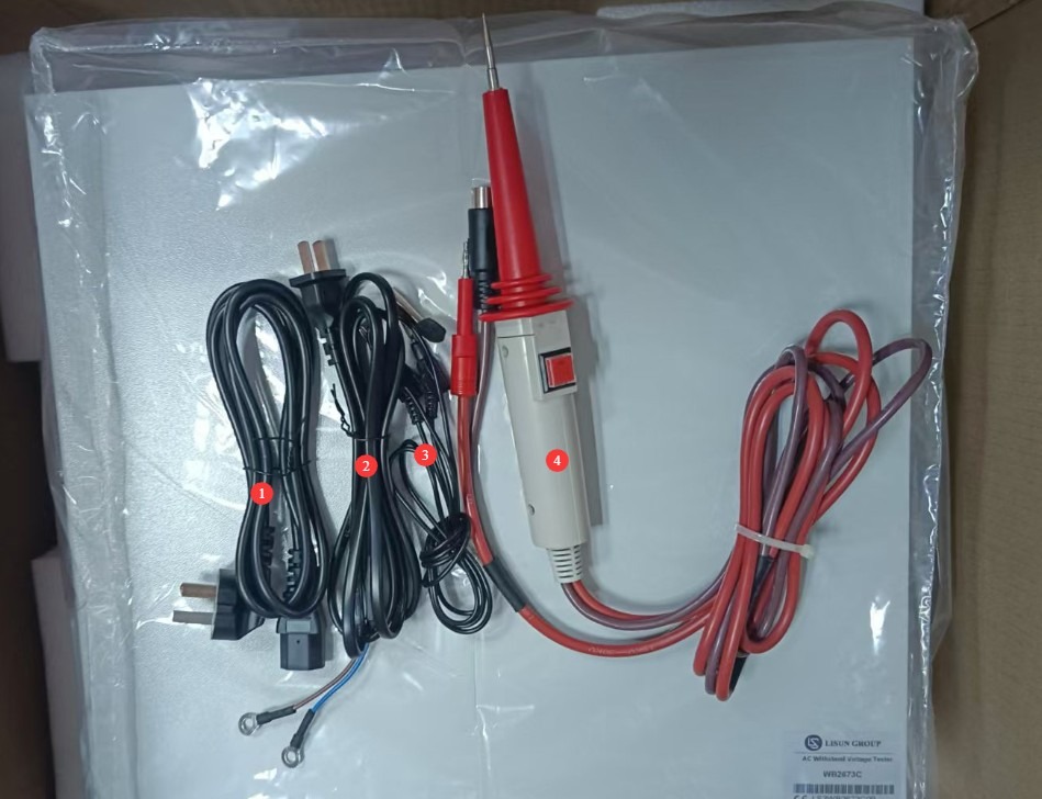
Gambar 1
Tautan unduhan untuk manual pengguna elektronik, perangkat lunak, kartu garansi, dan materi lainnya telah dikirim melalui email. Silakan unduh sesegera mungkin. Jika Anda melewatkan email tersebut, jangan ragu untuk menghubungi kami untuk meminta tautan unduhan lagi.
2 Tindakan Pencegahan Keamanan
2.1 Keamanan Listrik
2.1.1 Persyaratan Catu Daya
Gunakan stopkontak AC satu fasa 220V ±10%, 50/60 Hz tiga cabang; cabang pembumian harus dihubungkan ke tanah.
2.1.2 Persyaratan Pembumian
The instrument ground wire is reliably connected to the protective ground wire, and the protective ground resistance is ≤4Ω;
Do not short-circuit the output terminals to the AC power source to prevent the enclosure from becoming energized.
2.2 Keselamatan Lingkungan
2.2.1 Persyaratan Suhu dan Kelembaban
Hindari penggunaan perangkat di lingkungan dengan kelembapan melebihi 70% (tanpa kondensasi) atau di mana suhu berada di luar kisaran 0–35°C. Suhu pengoperasian optimal adalah 25±2°C.
2.2.2 Kontraindikasi Lingkungan
Lingkungan dengan medan magnet yang kuat dan medan listrik yang kuat;
Lingkungan yang mengandung gas atau cairan korosif;
Areas with flammable and explosive dust or hazardous materials;
Lingkungan dengan banyak debu, suhu dan kelembapan tinggi, serta sinar matahari langsung.
2.3 Keselamatan Operasional
Selama pengujian, wadah objek uji dialiri listrik; jangan menyentuhnya dengan tangan kosong dalam keadaan apa pun;
The test object must be placed on a rubber insulating mat;
Operator wajib mengenakan sarung tangan karet berinsulasi;
Jangan pernah menghubungkan langsung terminal keluaran tegangan tinggi (probe tegangan tinggi) ke terminal ground (penjepit ground), karena hal ini dapat menyebabkan transformator tegangan internal terbakar;
Operator harus memiliki tangan yang kering dan tidak boleh mengenakan perhiasan logam apa pun; makan atau minum dilarang selama pengujian untuk mencegah kecelakaan yang disebabkan oleh sengatan listrik;
Sebelum mengganti objek uji, Anda harus terlebih dahulu menghentikan pengujian dan memverifikasi bahwa tegangan keluaran perangkat adalah 0;
Jika melibatkan beberapa orang, tetapkan peran dan tanggung jawab dengan jelas, dan konfirmasikan satu sama lain sebelum memulai pengujian untuk menghindari kesalahan.
2.4 Lainnya
Untuk hal-hal yang tidak tercakup dalam panduan ini, harap berhati-hati atau hubungi kami.
3. Ikhtisar Peralatan
3.1 Pengenalan Panel Depan Peralatan
| Jumlah | Note |
| ① | Saklar daya |
| ② | High-voltage output connector, used to connect to the live parts of the device under test |
| ③ | Remote-controlled outlet; remote control wire connected to the high-voltage rod |
| ④ | Hubungkan penjepit pembumian; gunakan ujung colokan pisang untuk menghubungkan ke instrumen, dan ujung penjepit untuk menghubungkan ke perangkat yang sedang diuji. |
| ⑤ | Test Time Settings: You can set the test duration from 1 to 99 seconds for use with a timer switch. |
| ⑥ | Tampilan waktu pengujian, dalam detik. Catatan: Hanya tersedia saat sakelar pengatur waktu diaktifkan. |
| ⑦ | Jendela tampilan arus bocor: Menampilkan ambang batas alarm dalam mode siaga dan arus bocor waktu nyata dalam mode uji, dalam mA. |
| ⑧ | Jendela tampilan tegangan keluaran, menunjukkan nilai tegangan keluaran tinggi saat ini dalam kV. |
| ⑨ | Indikator Status Pengujian: TE: Sedang diuji; NG: Arus bocor melebihi ambang batas + bel berbunyi |
| ⑩ | Current adjustment knob: Sets the alarm current threshold; used in conjunction with the alarm selection button. |
| ⑪ | Tombol Preset/Uji: Tekan untuk masuk ke mode preset; dorong ke atas untuk masuk ke mode uji. |
| 1 | Timer switch: Press to enable the timer; release to disable it. |
| ⑬ | Residual Current Range Selection Button; the ranges are interlocked, so only one range can be selected at a time. |
| ⑭ | Tombol pengatur tegangan keluaran: Putar searah jarum jam untuk meningkatkan tegangan keluaran; putar berlawanan arah jarum jam untuk menurunkannya. |
| 3 | Tekan tombol Mulai untuk memulai pengujian; lampu indikator pengujian akan menyala. |
| 5 | Tombol reset: memutus tegangan keluaran, menghentikan pengujian, dan menghapus alarm. |
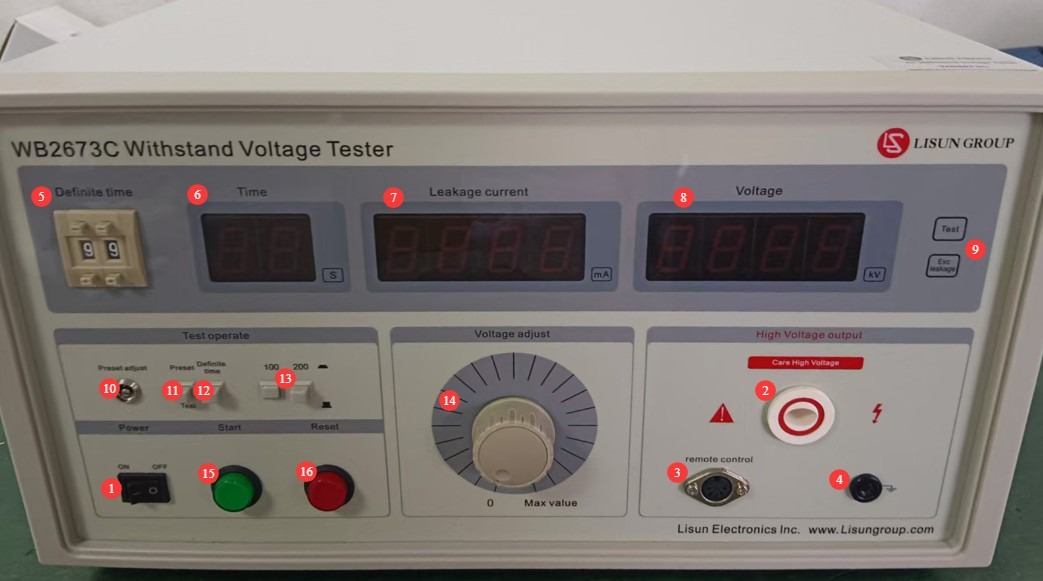
Gambar 2
Catatan: Setelah kabel kendali jarak jauh terhubung, tombol daya dan reset pada panel depan perangkat tidak akan berfungsi.
3.1 Introduction to the Equipment Back Panel
| Jumlah | Note |
| ① | Power cord receptacle, with built-in fuse |
| ② | To connect the test power supply terminals, use the test power supply connection cable to connect to a 220 V AC ±10%, 50/60 Hz power source. |
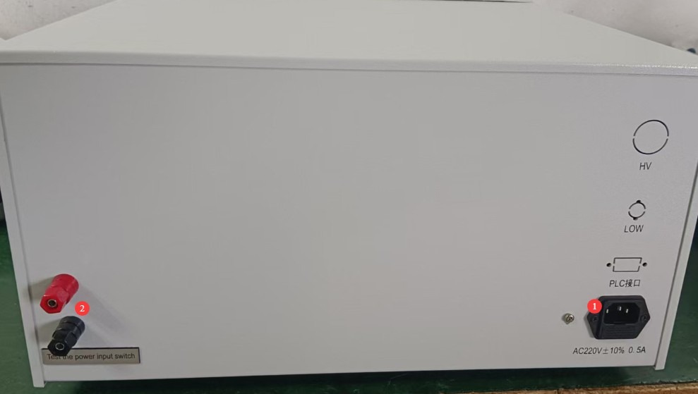
Gambar 3
4. Persiapan Sebelum Pengujian
4.1 Menghidupkan Peralatan
Plug the power cord into a standard three-prong outlet, press the power switch, and the instrument’s display will light up. The TE and NG indicator lights will be off, and the leakage current and voltage displays will show 0. If there are no abnormal audible or visual alarms, this indicates that the device’s power-on self-test was successful.
4.2 Persiapan Spesimen Uji
Selubung benda uji harus bersih dan bebas dari minyak; letakkan di tengah alas isolasi, jauh dari permukaan logam benda kerja.
5. Prosedur Uji
5.1 Pengaturan Parameter Uji
All parameter presets must be completed by following the steps below, with the high-voltage rod, remote control cable, and grounding clamps removed.
5.1.1 Selection of Leakage Current Range
Select the appropriate leakage current range button based on the standard requirements for the test item.
5.1.2 Mengatur Ambang Batas Alarm Arus Bocor
Switch the Preset/Test button to the preset state.
Slowly turn the current adjustment knob while observing the leakage current display window, and adjust the value to the alarm threshold specified in the test item’s standards.
Once the settings have been configured, switch the Preset/Test button to the Test mode; the leakage current display will return to 0, and the alarm value will be automatically saved.
5.1.3 Menentukan Durasi Tes
Pilih mode manual atau mode pengatur waktu sesuai dengan persyaratan standar pengujian:
Manual Mode: Flip the timer switch to the “On” position; there is no need to set a time—the operator manually controls the test duration.
Timer Mode: Press the timer switch to set the test duration to the required length (1–99 seconds); the time will be displayed as a countdown.
5.1.4 Pengaturan Tegangan Keluaran
Press the Start button and observe the value displayed in the output voltage display window. You can adjust it to the standard required value by turning the output voltage adjustment knob. Once adjusted, press the Reset button.
Catatan: Untuk pengujian dengan laju kenaikan tegangan yang ditentukan, jangan mengatur tegangan terlebih dahulu; cukup putar kenop ke 0. Setelah pengujian resmi dimulai, putar kenop secara perlahan untuk menyesuaikan tegangan keluaran ke tegangan uji pada laju yang ditentukan dalam standar.
5.2 Pengkabelan Peralatan
| petunjuk | Note |
| ① | Insert the banana plug end of the grounding clamp into the instrument’s connector, and verify that the ground terminal or metal casing of the device under test is securely connected to the clamp’s grounding terminal. |
| ② | Colokkan kabel kendali jarak jauh untuk batang tegangan tinggi yang dikendalikan dari jarak jauh dengan aman ke soket kendali jarak jauh pada unit utama. |
| ③ | Securely connect the high-voltage probe cable to the AC high-voltage output port on the main unit, and keep the high-voltage probe’s output end away from the test object for the time being. |
5.3 Uji Tegangan Tahan
5.3.1 Uji Startup
Place the output end of the high-voltage probe in close contact with the live parts of the test object (such as the power cord input or the winding leads). Then press the output control button on the high-voltage probe to begin the test.
5.3.2 Akhir Pengujian
Dalam mode pengatur waktu, ketika hitungan mundur berakhir, tegangan tinggi akan otomatis terputus dan pengujian berhenti; dalam mode manual, pengujian berhenti ketika Anda melepaskan tombol kontrol probe tegangan tinggi.
If any of the following abnormalities occur during testing, the test must be stopped immediately: smoke, unusual noises, or sparks from the test item; unusual noises, strange odors, or a black screen on the display. After an emergency stop, investigate the cause of the abnormality; do not resume testing until the problem has been resolved.
5.4 Evaluasi Hasil Tes
Hasil pengujian dievaluasi terutama berdasarkan apakah terjadi kerusakan dan apakah arus bocor melebihi ambang batas.
5.4.1 Kriteria Penerimaan
Throughout the entire test, the voltage remained stable at the standard requirement value, and the real-time leakage current remained below the set alarm threshold at all times; the “NG” indicator light and buzzer alarm were not triggered.
5.4.2 Kriteria untuk Menentukan Ketidaksesuaian
During testing, if the leakage current exceeds the alarm threshold, the “NG” light turns on and the buzzer sounds.
Spesimen uji menunjukkan tanda-tanda kerusakan yang jelas, lonjakan tegangan, asap, dan lain-lain.
6. Pemeliharaan dan Perawatan Peralatan Harian
6.1 Perawatan Rutin
Before turning on the equipment, check to ensure that the exterior is clean and undamaged, that the cables show no signs of aging or breakage, and that the connectors are secure; Check the grounding clamps for oxidation or burn marks; if present, wipe them with a specialized contact cleaner, and contact us to replace parts if necessary; after testing is complete, disconnect the power and wipe down the equipment surface and the test area with a dry, antistatic cloth.
6.2 Penyimpanan Jangka Panjang
When the device is not in use for an extended period, store it in a dry, well-ventilated environment, away from moisture and direct sunlight; disconnect all cables, store accessories separately, and cover the device with a dust-proof cloth; turn the device on for 30 minutes once a month to prevent the internal electronic components from deteriorating.
7. Pemecahan Masalah dan Penyelesaian Masalah Umum
| Gejala Kesalahan | Kemungkinan penyebab | Prosedur |
| Perangkat tidak mau menyala | The power cord isn’t plugged in securely; the fuse has blown. | Check the power cord connections; check the fuse in the device’s power input port; if it is blown, replace it with a fuse of the same type. |
| After startup, the display flickers and the keys do not respond. | Unstable power supply voltage | Use a multimeter to measure the supply voltage and verify that it is within the range of AC 220 V ±10%. If the voltage is unstable, install a voltage regulator. |
| Unjustified alarms during testing | Pemilihan rentang arus bocor yang salah; pengaturan ambang batas arus alarm yang salah. | Silakan pilih rentang arus bocor yang tepat terlebih dahulu, lalu sesuaikan ambang batas arus alarm. |
Appendix A: Summary Table of AC Withstand Voltage Test Requirements in Relevant Standards
| Nomor Standar | Jenis Produk Elektronik yang Tercakup | Dielectric Withstanding Voltage Test Requirements | Breakdown Current / Leakage Current Limits | Durasi Tes | Other Testing Requirements |
| GB/T 24344-2009/IEC 60204-1:2021 | Electrical and electronic equipment and systems for industrial machinery; electrical systems for machinery with a rated voltage of ≤1000 V AC or 1500 V DC | 1. Basic insulation: 2 × rated voltage + 1000 V, with a minimum of 1500 V AC; 2. Rated voltage ≤ 60 V: 500 V AC; 3. 60 V < rated voltage ≤ 300 V: 1000 V AC; 4. 300 V < rated voltage ≤ 690 V: 1500 V AC; 5. Frequency: AC voltage between 45 Hz and 65 Hz, with a waveform approximating a sine wave, and a peak-to-root-mean-square (RMS) ratio within √2 ± 0.07 | The test is considered successful if there are no breakdowns or flashovers; leakage current serves as a supplementary evaluation criterion, and there is no specific fixed limit. | 1. Standard test: 1 minute; 2. Rapid test: at least 1 second (as specified in IEC 60204-1:2021) | 1. The test voltage should start at 0 and be increased uniformly to the specified value; avoid sudden voltage increases; 2. After the test, slowly reduce the voltage to zero; 3. Applicable to dielectric strength tests for industrial machinery and electrical equipment, covering protection against electric shock, equipment protection, and more. |
| GB 4706.1-2024/IEC 60335-1:2023 | Household and similar electrical appliances with a rated voltage not exceeding 250 V for single-phase appliances and 480 V for other appliances, including refrigerators, air conditioners, electric irons, blenders, and other types of home appliances | 1. Basic insulation: 1000 V + 2× rated voltage, minimum 1500 V AC; 2. Reinforced insulation: 2000 V + 4× rated voltage, minimum 3000 V AC;3. Class 0 and Class I appliances: 1250 V AC; 4. Class II appliances: 1750 V AC; 5. Frequency: 50 Hz/60 Hz power-frequency sine wave | 1. The test is considered satisfactory if no breakdown, arcing, or flashover occurs during the test; 2. The high-voltage power supply must be capable of supplying the specified short-circuit current when a short circuit occurs at the output;3. Leakage current limits: 0.25 mA for Class II equipment; 0.5 mA for Class 0, Class I, and Class III equipment | 1. Routine testing: 1 minute; 2. In special cases, follow the specific provisions of the standard. | 1. The test shall be conducted at room temperature; for Class 0 and Class I appliances, a moisture treatment must be performed prior to the test; 2. For Class II designs that feature both reinforced insulation and double insulation, care must be taken to ensure that the voltage applied to the reinforced insulation does not cause excessive stress on the basic insulation or supplementary insulation;3. When testing the insulating covering, sandbags may be used to apply a pressure of approximately 10 kPa. |
| GB 19212.1-2021/IEC 61558-1:2022 | Voltage Transformers, reactors, power supply units, and their combined products, including Isolation Transformers, safety isolation transformers, autotransformers, and variable transformers; switching power supplies, inductive ballasts, chargers, etc., with a rated voltage not exceeding 1000 V AC or 1500 V DC. National Standard Information Public Service Platform | 1. Between windings and between windings and the housing: 2500 V to 4000 V AC (determined based on the insulation class and rated voltage);2. Basic insulation: 1000 V + 2× rated voltage; 3. Reinforced insulation: 2000 V + 4× rated voltage; 4. Frequency: 50 Hz/60 Hz power-frequency voltage | The test is considered satisfactory if no breakdown or arcing occurs; the leakage current must comply with the product-specific safety requirements. | 1 minute (60 seconds) | 1. The test voltage shall be gradually increased to the specified value within 5 seconds; 2. Applies to general safety requirements for Voltage Transformers, reactors, power supply units, and combinations thereof; 3. Emphasizes the ability to maintain protection against electric shock, overheating, and mechanical injury even under single-fault conditions |