
 Inggris
 中文简体
中文简体 Русский
 Español
 Português
 Türkçe
 العربية
 Deutsch
 Polski
 Italiano
 Français
 한국어
한국어 ไทย
ไทย Tiếng Việt
 日本語
日本語





























Kamar Uji Penuaan UV
Pengguna manual
berlaku LISUN Model: UV-263LS
1. Membuka Kemasan dan Mengenal Peralatan
1.1 Spesifikasi Teknis Utama
| LISUN Pilih Model | UV-263LV | UV-263LS | UV-263LT |
| Struktur Kandang | Ruang Dalam Trapesium | Square Inner Container | Desktop Enclosure |
| Inner Chamber Dimensions (W x D x H) | 450 × 1140 × 500 mm | 550 × 1140 × 450 mm | 500 × 400 × 400 mm |
| Outer Box Dimensions (W x D x H) | 600 × 1325 × 1500 mm | 650 × 1300 × 1750 mm | 930 × 460 × 630 mm |
| Rentang Suhu | Suhu ruang + 10°C hingga 70°C | ||
| kelembaban Rentang | ≥75% RH | ||
| Control System | The LCD programmable controller simulates UV exposure, high temperatures, high humidity, rain, condensation, darkness, and other conditions. | ||
| Spesifikasi Lampu UV | 8 U. S. ATLAS fluorescent tubes, 1200 mm long, 40 W each, 1000 hours per tube | Made in China, 20W per bulb, 3 bulbs total | |
| Wavelength Range of UV Lamps | Standard UVA-340 lamp: Wavelength range 315–400 nm, peak wavelength 340 nm (Optional UVB-313 lamp: Wavelength range 280–315 nm, peak wavelength 313 nm; Additionally, a UVA-351 lamp is available as an option: wavelength range 315–400 nm, peak wavelength 351 nm) | Standard UVA-340C lamp: Wavelength range 315–400 nm, with a peak wavelength of 340 nm (UVB-313C available as an option) | |
| Intensitas iradiasi | 0.35–1.2 W/m², adjustable (with built-in irradiance meter) | ||
| Temperature of the irradiated blackboard | 50 ° C – 70 ° C | ||
| Dimensi Spesimen | 48 pieces, 70 × 150 mm | Irregular specimens | 18 pieces, 70 × 150 mm |
| Water Sources and Consumption | 8 to 10 liters of purified water or distilled water per day (to be provided by the customer) | ||
1.2 Membuka Kemasan dan Memeriksa Isinya
1.2.1 Membuka Kemasan dan Pemeriksaan Visual
When unpacking the equipment, handle it gently to avoid scratching the exterior casing with sharp tools. After unpacking, first inspect the exterior of the main unit to ensure there is no visible deformation, dents, or peeling paint, and that the panel instruments and buttons are not damaged or loose. If you discover any damage or deformation to the equipment or accessories, do not power it on. Contact LISUN Layanan pelanggan segera.
1.2.2 Unit Utama dan Aksesoris
UV aging test Chamber (main unit): 1 unit.
Unless otherwise specified, this equipment does not include any other accessories.
Download links for the electronic user manual, warranty card, and other documents have been sent via email. Please download them as soon as possible. If you missed the email, please feel free to contact us to request the download links again.
1.3 Deskripsi Struktur Peralatan
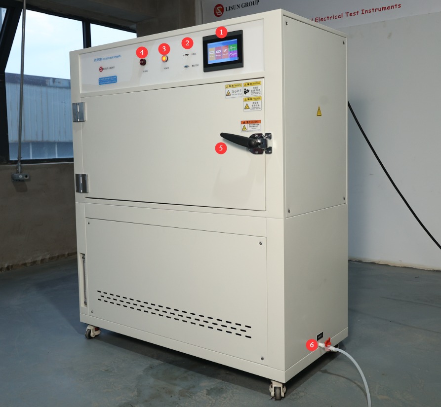
1.3.1 Front and Right Side of the Test Chamber
① Touchscreen; ② USB port for software updates or exporting test curves; RS-232 port (for backup); ③ Power switch; ④ Alarm—sounds when the device detects an abnormality, such as a lack of water; ⑤ Test chamber door; ⑥ Drain valve—open only when draining the water tank is necessary.
Gambar 1
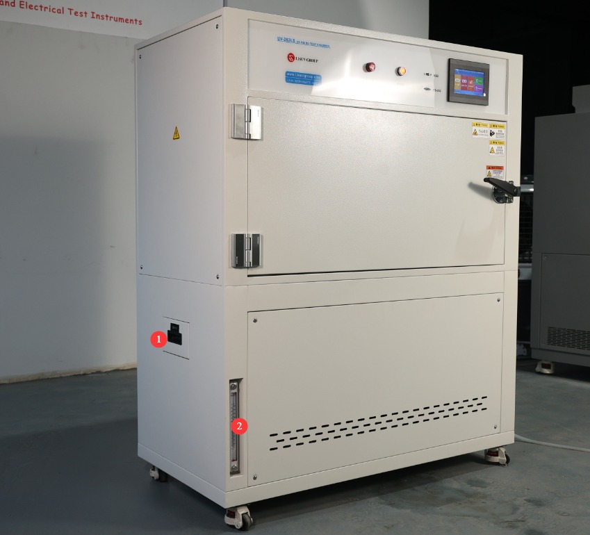
1.3.2 Left Side of the Test Chamber
① Water-filling drawer; ② Water level viewing window.
Gambar 2
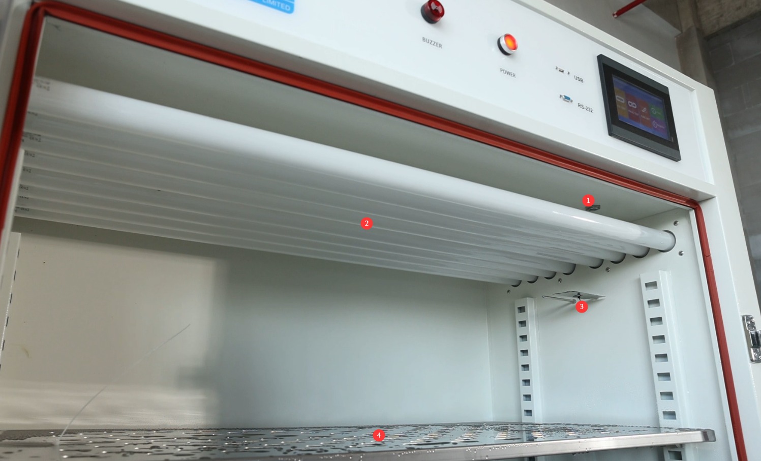
1.3.3 Di Dalam Ruang Uji
① Optical Fiber; ② UV lamp; ③ Blackboard temperature probe and test chamber temperature probe; ④ Sample rack.
Gambar 3
2. Tindakan Pencegahan Keamanan
2.1 Keamanan Listrik
2.1.1 Koneksi Daya
Daya listrik satu fasa 220V; stopkontak harus memenuhi standar keselamatan, diarde dengan benar, dan memiliki arus nominal yang sesuai dengan daya peralatan (disarankan untuk memasang pemutus sirkuit khusus).
2.1.2 Spesifikasi Pembumian
The equipment must be reliably grounded, with a grounding resistance of ≤50 Ω. Do not use gas pipes, non-metallic water pipes, or the neutral wire as a substitute for the ground wire. After grounding is complete, use a Grounding Resistance Tester to measure the grounding resistance. Power may only be applied after confirming that it meets the requirements, to prevent electric shock, equipment malfunctions, or measurement errors caused by poor grounding.
2.1.3 Kontraindikasi untuk Prosedur
Before wiring, inspecting, or maintaining the equipment, you must turn off the circuit breaker on the back of the equipment and disconnect the main power supply. Only proceed after confirming that there is no residual voltage;
Jangan mengoperasikan sakelar daya peralatan, layar sentuh, atau tombol instrumen dengan tangan basah untuk menghindari risiko sengatan listrik;
Jangan meletakkan benda asing apa pun (seperti perkakas atau kertas) di dalam kabinet kontrol listrik untuk mencegah debu atau benda asing menyebabkan korsleting atau merusak komponen;
Jangan mencolokkan atau mencabut kabel daya atau kabel sinyal saat peralatan sedang beroperasi untuk mencegah korsleting yang dapat merusak pengontrol atau komponen listrik.
2.2 Keselamatan Operasional
2.2.1 Persyaratan Spesimen Uji
The equipment must not be used for testing flammable, explosive, toxic, or highly corrosive substances (such as alcohol, gasoline, strong acids, strong alkalis, etc.). Since the equipment is not equipped with explosion-proof devices, such substances may cause fires, explosions, or corrosion of the equipment;
The sample volume must not exceed 80% of the basket’s capacity, and the weight must not exceed the equipment’s specified load capacity (shelf load capacity ≤ 20 kg).
2.2.2 Keselamatan Operasional
Saat peralatan sedang beroperasi, orang awam dilarang membongkar atau memperbaikinya. Jika terjadi kerusakan, hubungi petugas layanan purna jual atau operasikan peralatan di bawah bimbingan teknisi;
Do not open the chamber door during the test. The lamps emit intense ultraviolet radiation when in operation, which may cause severe sunburn or eye inflammation (similar to “snow blindness”);
Do not set the temperature beyond the range specified for the equipment;
When placing samples, distribute them evenly on the shelves; do not overcrowd them. Leave at least one-third of the space empty to ensure proper circulation of hot air inside the chamber and prevent localized temperature variations;
If the equipment triggers an alarm, immediately stop the test and troubleshoot the problem (see “Chapter 7: Troubleshooting and Resolution of Common Problems”). Do not force the equipment to restart; operating it before the problem is resolved may cause further damage to the equipment.
2.2.3 Perilaku yang Dilarang
Jangan membuka pintu kabinet kontrol saat peralatan sedang beroperasi untuk menghindari menyentuh komponen tegangan tinggi di dalamnya dan menyebabkan sengatan listrik;
Do not disassemble core components such as temperature sensors and heating elements without authorization. Modifying the equipment will void the warranty and may lead to safety incidents;
Do not place heavy objects (such as tools or accessories) on top of the equipment to avoid damaging the equipment panel or interfering with heat dissipation;
Do not stack flammable items (such as cardboard boxes, plastic wrap, etc.) around the equipment.
2.3 Keselamatan Lingkungan
2.3.1 Persyaratan Instalasi
The equipment must be installed in an air-conditioned room where the ambient temperature is maintained between 5°C and 25°C and the relative humidity is ≤85%. If the ambient humidity is high, condensation may form near the equipment door and test ports; in such cases, increase ventilation in the room or use a dehumidifier;
Lokasi pemasangan harus bebas dari konsentrasi debu yang tinggi, gas korosif (seperti sulfur dioksida dan klorin), dan atmosfer yang mudah terbakar atau meledak. Sinar matahari langsung tidak boleh menyinari peralatan untuk mencegah korosi pada wadah peralatan dan kerusakan komponen listrik;
Keep the device away from locations where ambient temperature fluctuates significantly, such as near vents or doorways, to prevent the device’s temperature control accuracy from being affected.
2.3.2 Persyaratan Ruang
The distance between the equipment enclosure and the wall, as well as surrounding structures (such as other test equipment and shelving), must be at least 1500 mm to ensure unobstructed ventilation at the equipment’s heat vents (rear and sides);
Setidaknya harus ada ruang selebar 2000 mm pada bukaan pintu peralatan untuk memastikan pintu dapat dibuka ke segala arah, sehingga memudahkan penempatan dan pengambilan sampel.
2.3.3 Penempatan Horizontal
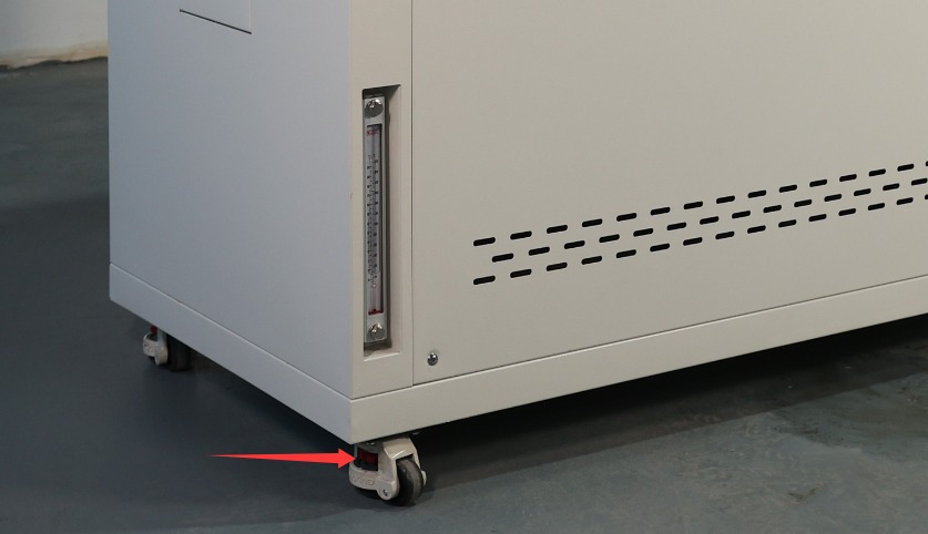
The equipment must be placed on a level surface. Use a spirit level to ensure the equipment is level: Place the spirit level on the top surface of the equipment and confirm that the bubble is centered. Note: The following types of legs are adjustable to ensure the test chamber is level.
Gambar 4
If the equipment is tilted, it may cause uneven temperature distribution inside the chamber and poor door sealing, which can affect test results and the equipment’s service life.
2.4 Lainnya
Untuk hal-hal yang tidak tercakup dalam panduan ini, harap berhati-hati atau hubungi kami.
3. Persiapan Sebelum Ujian
3.1 Filling the Water Tank
Open the machine’s water drawer and check inside the drawer and the water tank (to check the water tank, you’ll need to open the bottom panel on the front of the machine) for any debris or standing water (clean the inside of the water tank before using the machine for the first time).
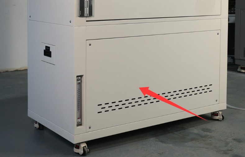
Gambar 5
Before adding water, check whether the drain valve on the tank is in the “closed” position (the valve is closed when it is parallel to the tank body and open when it is perpendicular to it); if the drain valve is not closed, close it immediately to prevent water leakage from the tank;
The water tank must be filled with purified water (do not use tap water or bottled water, to prevent limescale from clogging the humidifier or corroding the water lines). When adding water, check the water level markings inside the tank until it reaches the maximum water level line on the viewing window (do not exceed this level to prevent overflow). Close the water tank drawer after adding water.
3.2 Starting Up the UV Aging Test Chamber
Verify that the external power supply and ground connections are secure, then close the main circuit breaker on the back of the equipment (flip it upward to the “ON” position).
Press the “Power” button on the control panel. After 5 seconds, the meter will automatically display the main screen.
After powering on, check the instrument for any alarm indications. If an alarm is present, first refer to Chapter 7 to troubleshoot; if no alarm is present, the instrument will enter standby mode, and you may proceed with parameter configuration.
3.3 Prosedur Penempatan Sampel
3.3.1 Contoh Penempatan
Open the test chamber door, adjust the height of the internal shelves, and place the test specimens evenly on the shelves: ① Do not cover the test chamber temperature display or the blackboard; ② Do not touch the interior walls of the chamber; ③ Avoid touching the UV lamp.
3.3.2 Menutup Pintu Kabinet
Gently push the cabinet door to ensure it is fully seated against the cabinet’s weatherstrip, with no gaps (if there are gaps, check to see if the door has sagged or if the weatherstrip has deteriorated; make minor adjustments to the door hinges or clean the weatherstrip).
After closing the cabinet door, make sure the latch is securely engaged to prevent the door from opening unexpectedly during operation.
4. Program Operation via the Touchscreen on The UV Aging Test Chamber
4.1 Introduction to the System Main Screen
① Fixed-value test; ② Programmed test; ③ Operation settings; ④ Fault log; ⑤ Scheduled settings.
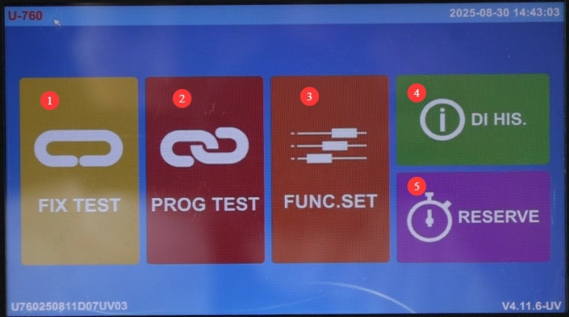
Gambar 6
4.2 Calibration Test
4.2.1 Pendahuluan tentang Layar Uji Kalibrasi
Click “Constant-Value Test.” ① Test chamber temperature display; ② Test chamber temperature setting; ③ Black plate temperature display;④ Blackboard temperature setting; ⑤ UV irradiation intensity display; ⑥ UV irradiation intensity setting; ⑦ Control mode selection (three modes available: condensation, UV, and spray); ⑧ Parameter settings; ⑨ Test curve; ⑩ Start/Stop test.
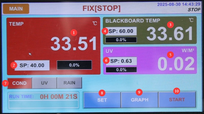
Gambar 7
4.2.2 Introduction to the Fixed-Value Parameter Settings Screen
Click “Settings.” ① For long-duration tests, set this to “ON” to configure the test duration; set it to “OFF” to stop the test manually. ② Spray settings: You can set the system to continuous or cyclic spraying.
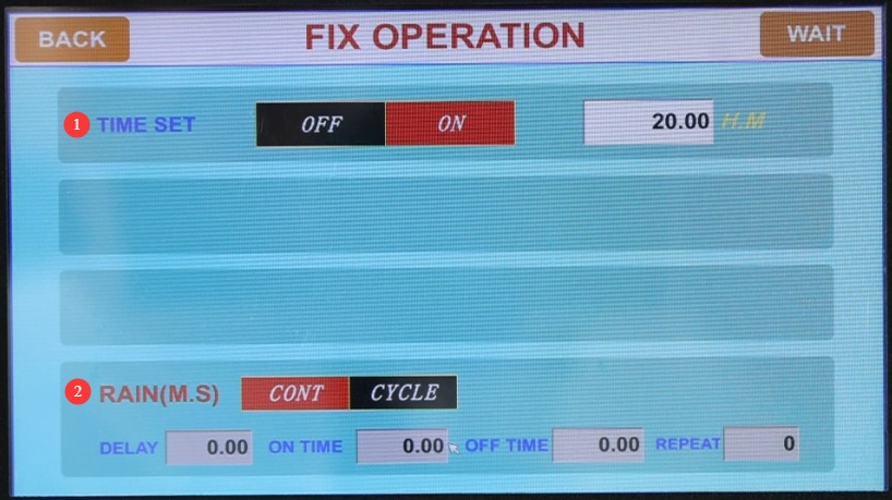
Gambar 8
4.2.3 Fixed-Condition Test in Condensation Mode
① Select the condensation mode; ② Simply set the temperature of the test chamber; ③ Once the test begins, the black panel heating and UV irradiation functions will not be activated.
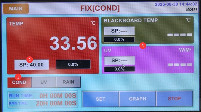
Gambar 9
4.2.4 UV Mode Calibration Test
① Select UV mode; ② Set the test board temperature; ③ Set the UV light intensity.
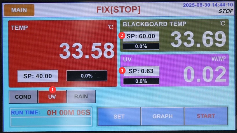
Gambar 10
① Click “Start Test”; ② Once the test begins, the temperature inside the test chamber will not be displayed; simply monitor the temperature on the blackboard and the UV light intensity.
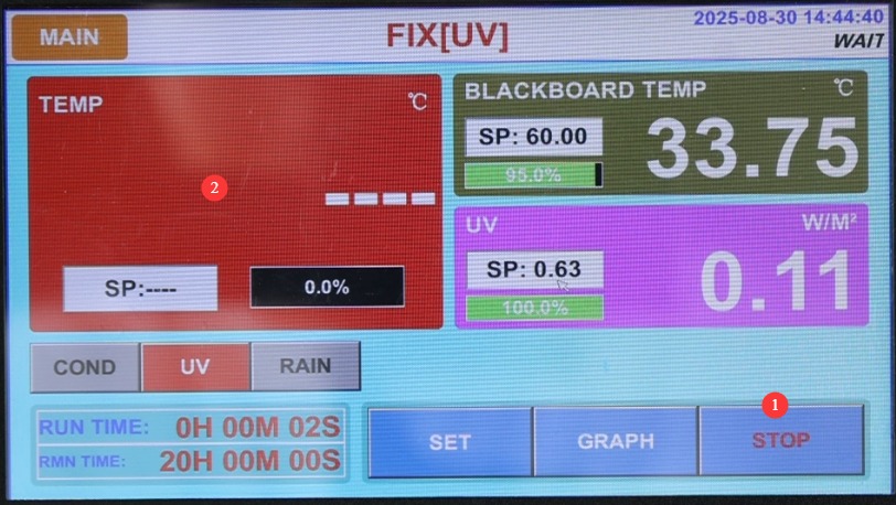
Gambar 11
4.2.5 Spray Mode Calibration Test
When the spray mode is selected, after the test begins, the test chamber temperature, black panel temperature, and UV irradiation functions will not be activated; only the spray test will be conducted.
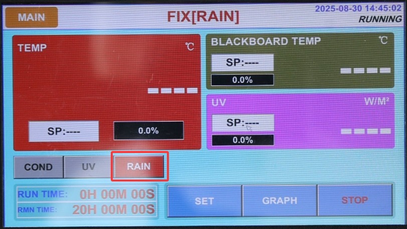
Gambar 12
4.3 Program Testing
4.3.1 Pendahuluan Layar Uji Program
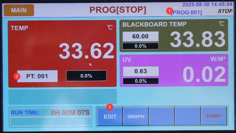
Click “Program Test.” ① Select and display the program number currently being executed; ② Display the segment number currently being executed; ③ Edit the program.
Gambar 13
4.3.2 Introduction to the Program Editor Screen
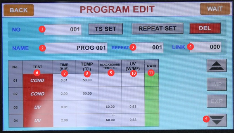
Click “Edit.” ① Enter the program number you want to edit; be sure to avoid duplicating existing program numbers. You can set up to 120 programs. ② Customize the program name. ③ Number of cycles; if no cycles are needed, enter 1.④ Link programs: If this program needs to automatically link to another program upon completion, enter the corresponding program number; otherwise, enter 0; ⑤ Switch to another test segment; ⑥ Set the test mode for this segment: condensation, UV, or spray;⑦ Test duration—set the duration for any test segments that are not required to -0.01; ⑧ Chamber temperature setting; ⑨ Black plate temperature setting; ⑩ UV irradiance setting; 11 Spray function switch—if this test segment involves spraying, set the spray function switch to ON.
Gambar 14
Note 1: If temperature or light intensity needs to be set for this test segment, the same parameters must be set for both segments. Segment 1 is the transition phase; set the test duration to 1 minute (the actual duration may exceed 1 minute), during which the test chamber will reach the required temperature or light intensity as quickly as possible. Segment 2 is the actual test phase; set the test duration to the required length. See the figure above.
4.3.3 Wait Function Settings
Click “WAIT” in the upper-right corner.
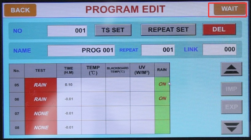
Gambar 15
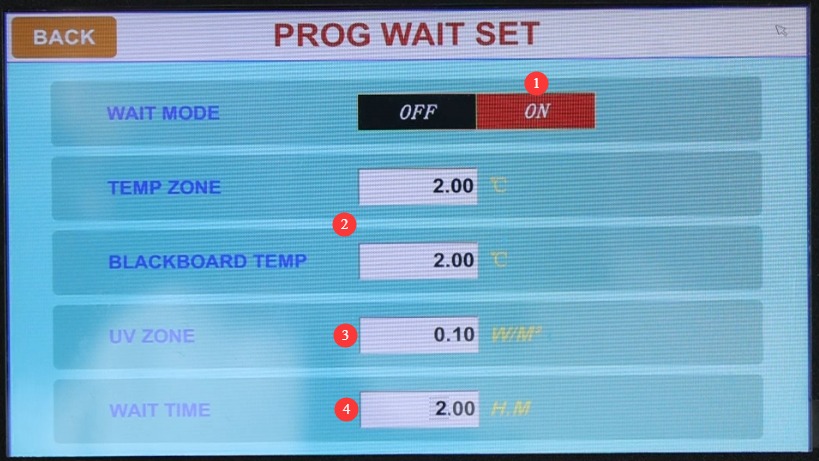
① The wait function must be enabled during program testing; ② Temperature wait range: If set to 2°C, the target temperature is considered achieved when the actual temperature differs from the target temperature by 2°C; ③ UV irradiance wait range: If set to 0.1, the target irradiance is considered achieved when the actual irradiance differs from the target irradiance by 0.1;④ Maximum wait time: If the target value is not reached within the maximum wait time, that segment will be skipped.
Gambar 16
The wait function is primarily used during transition phases in the program; that is, once the test chamber reaches the set temperature and light intensity, it automatically skips the transition phase and proceeds to the next phase for the formal test.
4.3.4 Program Testing
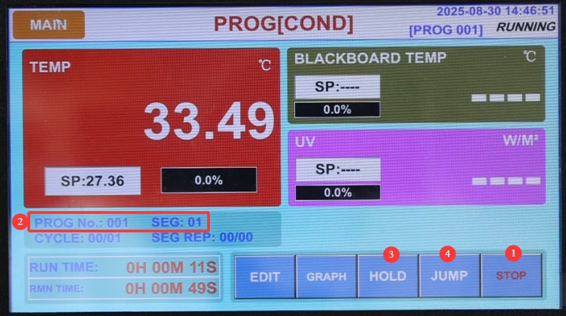
① Click “Start”; ② Displays the current program number and segment number; ③ “Hold” allows the program to continue running the current test segment until you click to cancel this function; ④ “Skip Segment”: Click to skip the current test segment.
Gambar 17
4.4 Introduction to the Operation Settings Screen
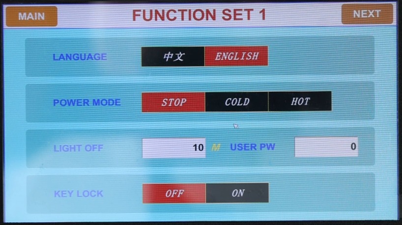
You can configure the display language and power-off restart mode (Stop: After a power outage during operation, the system returns to the “Stop” state when power is restored; Cold Start: After a power outage during operation, the system restarts from the first section and resumes operation when power is restored; Hot Start: After a power outage interrupts operation, the system continues from the section where it left off before the outage; when power is restored, the system returns to the state it was in before the outage) and other settings.
Gambar 18
4.5 Introduction to the Fault Log Screen
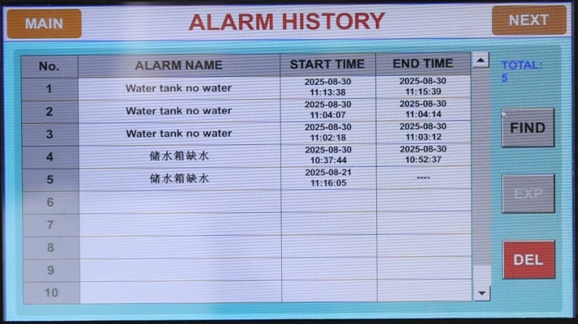
Display historical fault records.
Gambar 19
4.6 Introduction to the Appointment Settings Screen
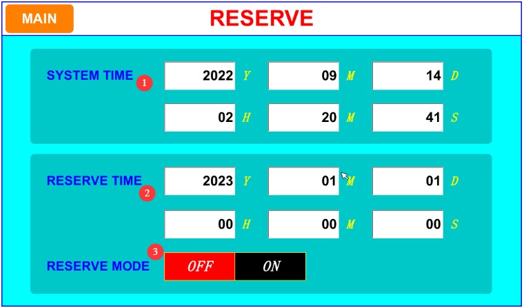
① Set the system’s current time; ② Set the scheduled time; ③ Scheduled operation feature: Once enabled, the device will automatically run the currently selected test at the scheduled time.
Gambar 20
4.7 Monitoring the Test Operation Process
Keep an eye on the water level in the tank; during the condensation test, the water level will drop as water evaporates. Please refill the tank promptly when the water level drops.
5. Prosedur Pasca-Ujian
5.1 Termination of the Test
Wait for the test to complete normally; the device will then enter standby mode. If you need to terminate the test early, click the “Stop” button on the corresponding screen, and the device will enter standby mode.
5.2 Pengambilan dan Penanganan Sampel
Wear protective gloves, open the test chamber door, remove the sample, and place it in the designated area. Record any changes in the sample’s appearance (such as fading or cracking), and conduct subsequent analysis in accordance with the test standards.
Note: Do not open the test chamber door while the UV lamp is on.
5.3 Immediate Cleaning of Equipment
Wipe down the sample rack and the interior surfaces of the equipment with a clean cloth to remove any residual dust or sample debris.
Check the water level in the tank. If the water level is low, top it off with purified water to the standard level (to make it ready for the next use).
If a spray test has been performed, open the drain valve to empty any remaining water from the tank, clean the tank, and then refill it with water.
5.4 Exporting and Saving Data
Verify that the USB flash drive is connected, go to the “Historical Data” or “Curves” screen, and select the test data or curves you want to export.
Click the “Export” button, wait for the export to finish, then safely remove the USB drive and back up the data to your computer.
Record key test information (such as program number, test duration, sample name, etc.) to facilitate subsequent traceability.
5. 5 Shutting Down the Equipment
If no further testing will be conducted that day, please turn off the test chamber and switch off the main circuit breaker on the back.
6. Pemeliharaan dan Perawatan Peralatan Harian
6.1 Pembersihan Reguler
Cleaning the Chamber: Clean the chamber every 3–6 months. After disconnecting the power supply, remove the sample rack and wipe down the sample rack, the bottom of the water tray, and the inner walls of the chamber to remove floating debris and solid impurities.
Tank Cleaning: Clean the tank once a month. Drain any accumulated water from the tank, then wipe down the inside walls with a clean cloth to remove scale and debris, preventing clogs in the nozzles or damage to the water pump.
Nozzle Cleaning: Inspect the nozzles once a week. If you notice uneven spraying or no water coming out, rinse the nozzles with clean water to remove any blockages (do not use hard objects to clear blockages).
Cleaning the Touchscreen: Wipe it with a dry, clean cloth, and avoid letting moisture seep into the screen’s crevices.
6.2 Maintenance and Replacement of Light Tubes
Inspect the appearance of the light tubes weekly. If you notice any cracks, discoloration, or abnormal flickering, replace them promptly.
Record the cumulative operating time of the lamp. When the irradiance drops significantly (below 80% of the set value), the lamp must be replaced even if it is not yet damaged.
When replacing the fluorescent tubes, remove the panels on both sides of the unit and unplug all the lamp sockets at both ends of the corresponding tubes, as shown in the figure below:
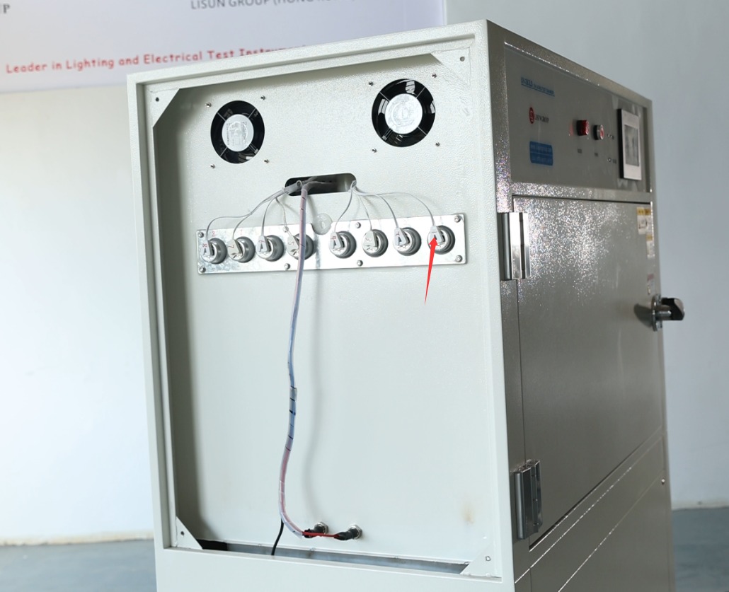
Gambar 21
Then, from inside the test chamber, slowly twist and pull out the fluorescent tube. Install the new fluorescent tube using the same method.
6.3 Equipment Storage and Maintenance During Idle Periods
Short-term storage (within 1 month): Drain any water from the water tank and drip tray, clean the inside and outside of the equipment, disconnect the power supply, leave it in its original location, and ventilate the area regularly.
Long-term inactivity (more than 1 month): In addition to the steps mentioned above, the equipment should be powered on once a month and left running for at least half an hour to prevent electrical components, such as capacitors, from deteriorating.
Before restarting: Check the power supply, piping, and the condition of the fluorescent tubes; clean the water tank and refill it with water; conduct a 30-minute test run to ensure there are no abnormalities before proceeding with the formal test.
7. Pemecahan Masalah dan Penyelesaian Masalah Umum
7.1 Startup Failures
7.1.1 Symptoms: The device fails to start, and the power indicator light does not illuminate.
Possible causes: A faulty external power switch, a tripped circuit breaker, or a loose power plug.
Solution: Check that the power plug is securely plugged in, and test the unit by plugging it into a different outlet; if the circuit breaker trips, check for a short circuit and then reset it; if the power switch is damaged, contact the manufacturer for repairs.
7.1.2 Symptom: The power indicator light is on, but the touchscreen does not respond
Possible causes: Touchscreen calibration error, controller malfunction.
Solution: Disconnect the power supply for 3 minutes, then reconnect it; go to the second screen in the operation settings to calibrate the touchscreen; if calibration fails, contact the manufacturer to have the controller repaired.
7.2 Operational Failures
7.2.1 Fault Symptom: Temperature/Irradiance Does Not Reach the Set Value During Operation
Possible causes: Aging lamp tubes, heater malfunction, sensor malfunction, or ambient temperature outside the specified range.
Solution: Check the total operating time of the lamp and replace it if necessary; ensure the ambient temperature is between 5 and 27°C and that ventilation is adequate; if the sensor or heater is malfunctioning, contact the manufacturer for repairs.
7.2.2 Fault Symptom: An alarm is triggered during operation
Possible causes: Low water level in the tank, loose connection in the lamp tube, or parameter settings outside the specified range.
Troubleshooting: View the alarm log screen to identify the type of fault; if the water tank is low on water, refill it with purified water; if there is a loose connection with the lamp tube, unplug and replug it; if the parameters are out of range, enter the settings menu and adjust them to the appropriate range.
7.3 Sprinkler System Malfunction
7.3.1 Symptom: Insufficient spray pressure; water flow is too weak
Possible causes: The water pump pressure is not set correctly, the water level in the tank is too low, or the nozzle is clogged.
Solution: Turn the pressure调节valve above the pump clockwise to increase pressure; top off the water tank to the standard level; and clear any blockages from the nozzles.
7.3.2 Symptoms: The pump starts but no water is sprayed
Possible causes: Lack of water in the pump, clogged pipes, or a completely clogged nozzle.
Solution: Disconnect the power supply and pour purified water into the pump’s inlet; check that the spray lines are clear; thoroughly clean or replace any clogged nozzles.
7.4 Kegagalan Komunikasi
7.4.1 Symptoms: The touchscreen displays “————,” and the data does not update.
Possible causes: Poor connection between the controller and the control board; damaged communication lines.
Solution: Disconnect the power supply, check whether the internal communication cables are loose, and reconnect them; if the cables are damaged, contact the manufacturer to have them replaced.
7.5 Data Export Issues
7.5.1 Symptoms: Unable to export data or curves
Possible causes: The USB flash drive is not formatted, poor contact at the USB port, or insufficient storage space on the device.
Solution: Format the USB drive to FAT32, then reconnect it; try a different USB drive; delete some old data to free up storage space.