
 Inggris
 中文简体
中文简体 Русский
 Español
 Português
 Türkçe
 العربية
 Deutsch
 Polski
 Italiano
 Français
 한국어
한국어 ไทย
ไทย Tiếng Việt
 日本語
日本語





























Melacak Kamar Uji
Pengguna manual
berlaku LISUN Model: TTC-1,TTC-1S
1. Membuka Kemasan dan Mengenal Peralatan Secara Dasar
1.1 Spesifikasi Teknis Utama
| LISUN Pilih Model | TTC-1 | TTC-1S |
| Nama Produk | Dengan perumahan | Without a case |
| Spesifikasi Elektroda | Rectangular platinum (purity > 99%), single-electrode pressure 1.0 N ± 0.05 N | |
| Voltage Application Range | 100 V–600 V AC; 1.0 A ± 0.1 A; voltage drop during a short-circuit current event ≤ 10% | |
| Perlindungan Arus Hubung Singkat | If the current exceeds 0.5A and remains above that level for more than 2 seconds, the power will automatically shut off and a “Failed” message will be displayed. | |
| Spesifikasi Cairan Terkontaminasi | 0.1% ammonium chloride solution, with a dedicated storage system | |
| Dispenser Parameters | Distance: 30–40 mm (adjustable); volume: 44–55 drops/cm³; interval: 30 s ± 5 s (adjustable) | |
| Pemantauan Arus Kebocoran | 0–100 mA (accuracy ±2%), with support for a 60 mA threshold-exceeding alarm | |
| Specimen Dimensions Requirements | Recommended dimensions: 100 mm × 100 mm × (2–10) mm; maximum thickness ≤ 15 mm (solid insulation material) | |
| Fitur Keselamatan | Overcurrent; Power Shutdown Due to Test Chamber Door Opening | |
| Bahan tubuh | Struktur baja berlapis suhu tinggi tahan panas dan tahan korosi, sehingga cocok untuk lingkungan pengujian suhu tinggi jangka panjang. | |
| Tampilan Operasi | Proprietary extra-large LCD touchscreen + clear indicator lights + remote control operation | |
| Berat | G. W. 180 kg | G. W. 40 kg |
1.2 Pemeriksaan dan Verifikasi Aksesori Saat Membuka Kemasan
1.2.1 Membuka Kemasan dan Pemeriksaan Visual
When unpacking the equipment, handle it gently to avoid scratching the exterior casing with sharp tools. After unpacking, first inspect the exterior of the main unit to ensure there is no visible deformation, dents, or peeling paint, and that the panel gauges and buttons are not damaged or loose. If any damage or deformation is found on the equipment or its accessories, do not turn on the power.
Buka pintu ruang uji dan periksa apakah ada komponen internal yang terlepas selama pengiriman atau apakah ada kelainan lain.
Jika Anda menemukan masalah, segera hubungi kami.
1.2.2 Unit Utama dan Aksesoris
Main unit of the Tracking Test Chamber: 1 unit.
Standard accessories include: ① exhaust pipe; ② adjustable tray; ③ pocket-sized electronic scale; ④ power cord;⑤ glass dish; ⑥ a pair of platinum electrodes; ⑦ spare fuses; ⑧ calibration gauge; ⑨ dropper tip; ⑩ ammonium chloride; ⑪ stainless steel clamps (for securing the exhaust pipe).
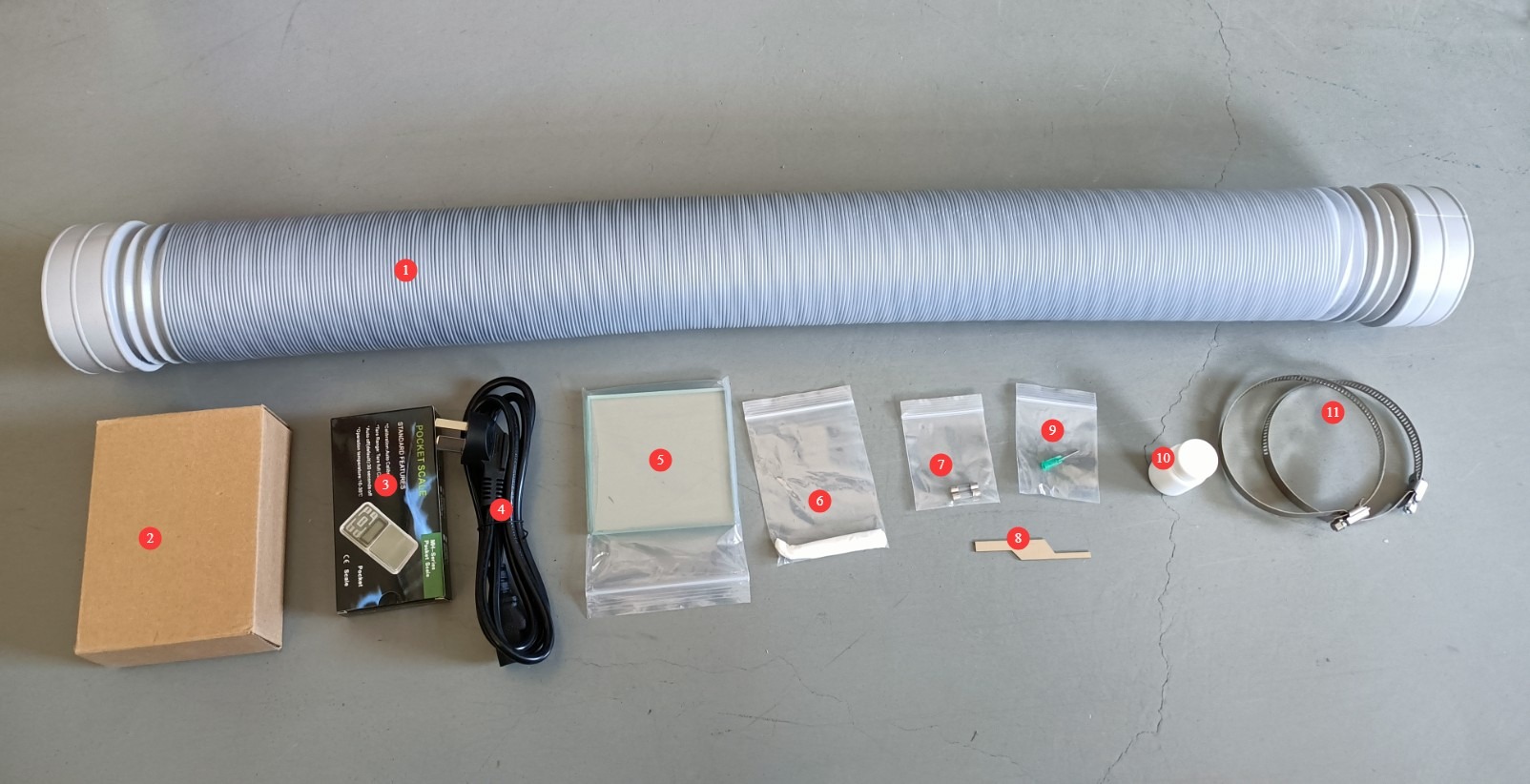
Gambar 1
Note: Download links for the electronic user manual, warranty card, and other documents have been sent via email. Please download them as soon as possible. If you missed the email, please feel free to contact us to request the download links again.
1.3 Deskripsi Struktur Peralatan
1.3.1 Tampilan Depan Ruang Uji
① Touchscreen; ② Power control: circuit breaker, power-on switch, and power on/off buttons; ③ Test current and short-circuit current displays, short-circuit current adjustment knob; ④ Test voltage display, test voltage range selector switch; ⑤ Test voltage adjustment knob.
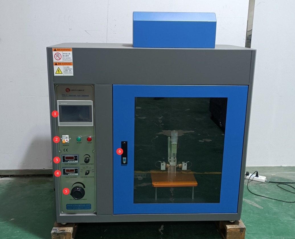
Gambar 2
1.3.2 Bagian Belakang Ruang Uji
① Exhaust vent, 100 mm in diameter, securely connected to an exhaust duct that extends to the outside; ② Power outlet.
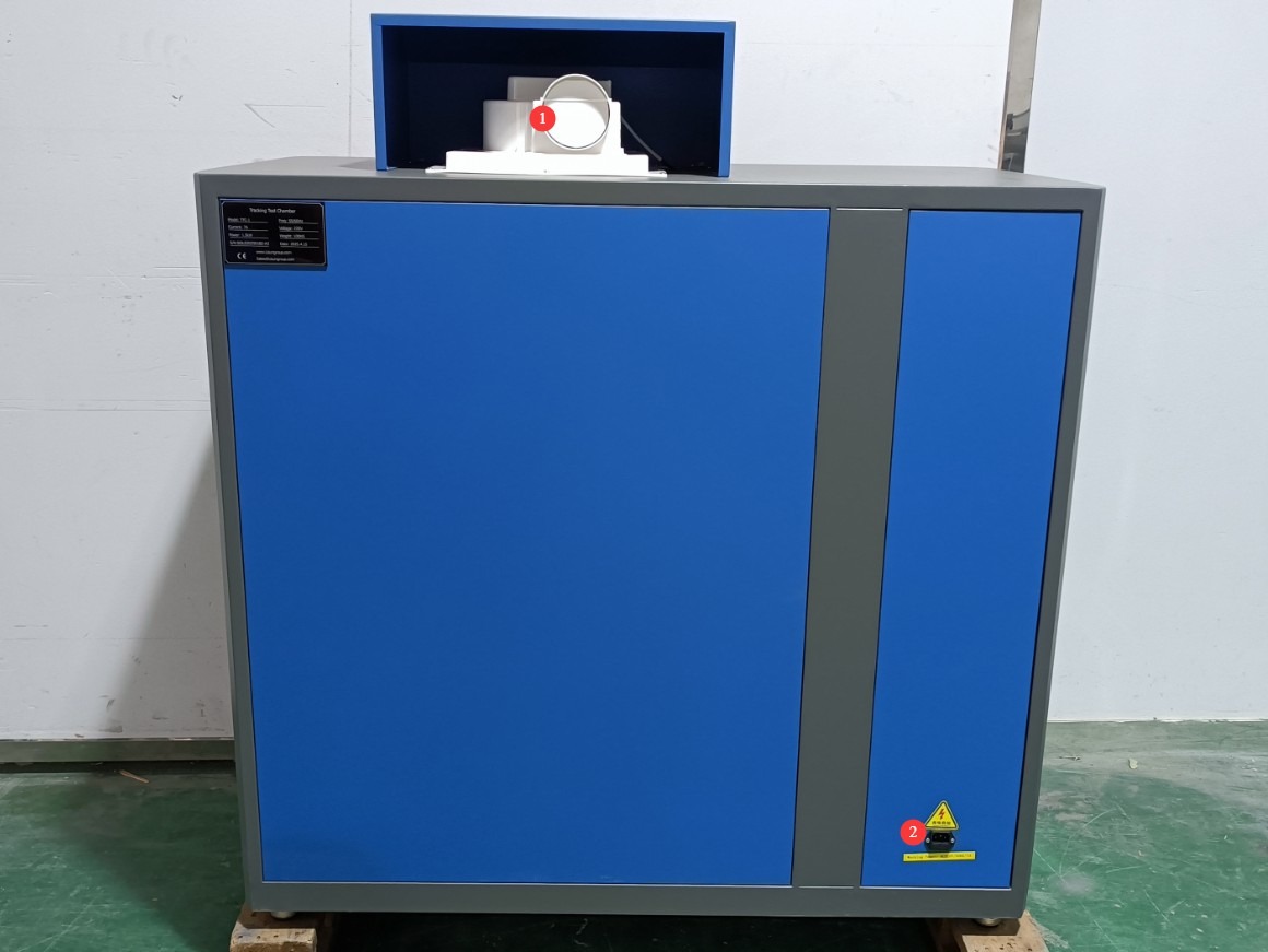
Gambar 3
1.3.3 Di Dalam Ruang Uji
A safety switch is installed between the chamber door and the test chamber. This means that the equipment cannot output a test voltage unless the chamber door is closed, ensuring operational safety. See the figure below:
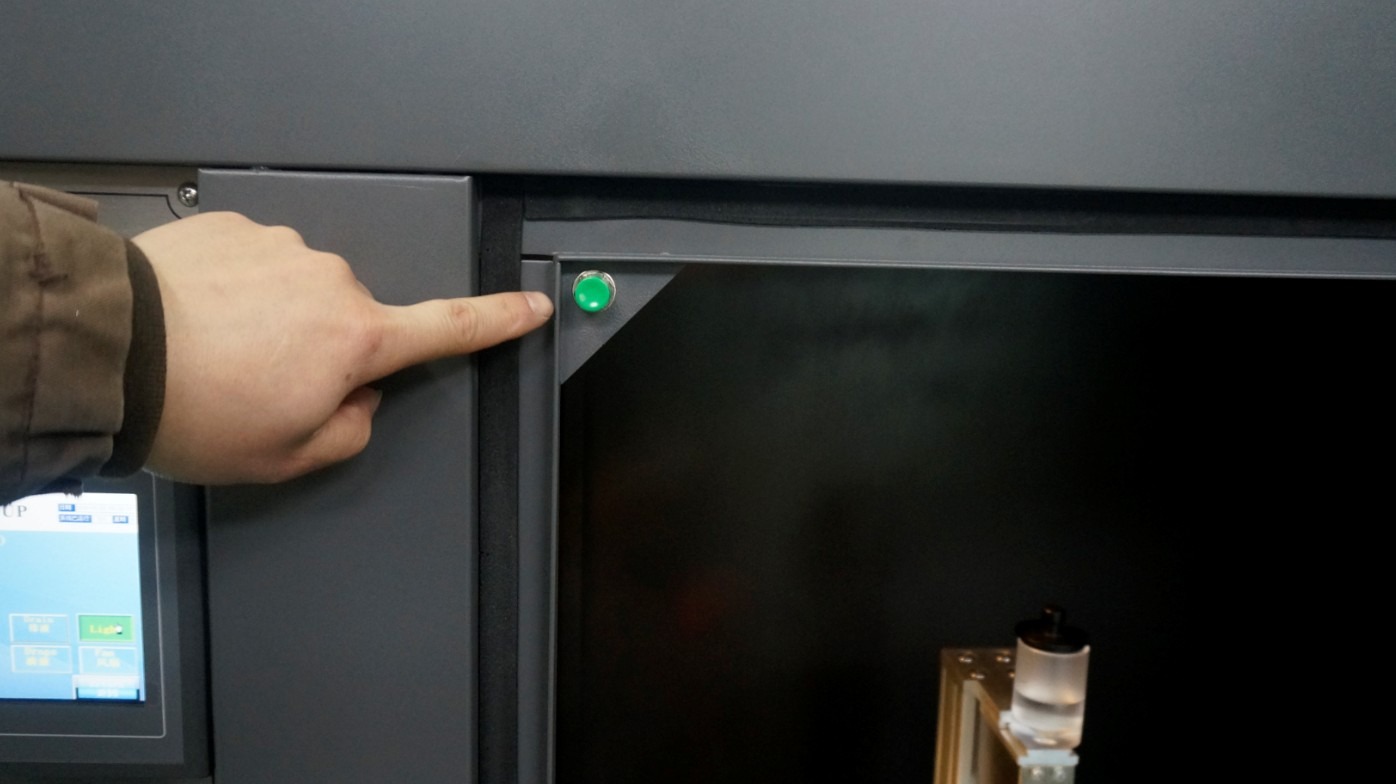
Gambar 4
Internal Structure: ① Solution cup; ② Solenoid valve inside to control solution dripping; ③ Needle; ④ Electrode holder, which allows adjustment of electrode pressure by changing the position of the counterweight.
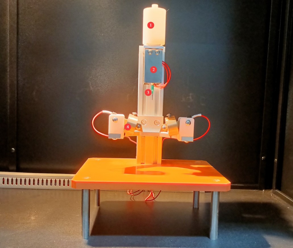
Gambar 5
Note: The internal design details of the equipment may vary depending on the model year, but the functionality remains the same and does not affect its use.
2. Tindakan Pencegahan Keamanan
2.1 Keamanan Listrik
2.1.1 Koneksi Daya
220V single-phase power; power outlets must comply with safety standards, have proper grounding, and have a rated current that matches the equipment’s power rating (it is recommended to install a dedicated circuit breaker).
We recommend using a regulated power supply. If the voltage fluctuates, the device’s output voltage will also fluctuate, which could affect the test results.
2.1.2 Spesifikasi Pembumian
The equipment must be reliably grounded, with a grounding resistance of ≤4 Ω. Do not use gas pipes, non-metallic water pipes, or neutral wires as substitutes for grounding wires. After grounding is complete, use a Grounding Resistance Tester to measure the grounding resistance. Power may only be applied after confirming that the resistance meets the requirements, to prevent electric shock, equipment malfunctions, or measurement errors caused by poor grounding.
2.1.3 Kontraindikasi untuk Prosedur
Sebelum melakukan pemasangan kabel, pemeriksaan, atau perawatan peralatan, Anda harus memutuskan aliran listrik utama ke peralatan dan memastikan tidak ada tegangan sisa sebelum melanjutkan;
Jangan mengoperasikan sakelar daya peralatan, layar sentuh, atau tombol instrumen dengan tangan basah untuk menghindari risiko sengatan listrik;
Jangan meletakkan benda asing apa pun (seperti perkakas atau kertas) di dalam kabinet kontrol listrik untuk mencegah debu atau benda asing menyebabkan korsleting atau merusak komponen;
Jangan mencolokkan atau mencabut kabel daya atau kabel sinyal saat peralatan sedang beroperasi untuk mencegah korsleting yang dapat merusak pengontrol atau komponen listrik.
2.2 Keselamatan Operasional
2.2.1 Keselamatan Operasional
Saat peralatan sedang beroperasi, orang awam dilarang membongkar atau memperbaikinya. Jika terjadi kerusakan, hubungi petugas layanan purna jual atau operasikan peralatan di bawah bimbingan teknisi;
During the test, the chamber door must be completely closed; it must not be opened midway to observe the test. Observation of the test process must be conducted through the chamber’s viewing window to prevent injury from electrolyte splashes or electrical discharges;
In the event of a malfunction or abnormality, immediately stop the test and troubleshoot the problem (see “Chapter 7: Troubleshooting Common Problems”). Do not force the equipment to start up; operating the equipment before the problem has been resolved may cause further damage to the equipment.
2.2.2 Perilaku yang Dilarang
Do not open the control cabinet door while the equipment is running to avoid touching internal high-voltage components and causing an electric shock;
Do not disassemble core components without authorization. Modifying the equipment will void the warranty and may result in safety incidents;
Do not place heavy objects (such as tools or accessories) on top of the equipment to avoid damaging the equipment panel or impairing heat dissipation;
Do not stack flammable materials (such as cardboard boxes, plastic wrap, etc.) around the equipment.
2.3 Keselamatan Lingkungan
2.3.1 Persyaratan Instalasi
The equipment must be installed in an air-conditioned room, with the ambient temperature maintained between 5°C and 25°C and relative humidity ≤85%. If ambient humidity is high, condensation may form near the equipment door and test ports; in such cases, improve room ventilation or use a dehumidifier;
The installation site must be free of high concentrations of dust, corrosive gases (such as sulfur dioxide and chlorine), and flammable or explosive atmospheres. Direct sunlight must not shine on the equipment to prevent corrosion of the equipment housing and deterioration of electrical components;
Penyimpanan bahan yang mudah terbakar dan meledak (seperti alkohol, bensin, dll.) dilarang keras di area pengujian untuk mencegah risiko kebakaran atau ledakan;
The work area is equipped with fire extinguishers (dry powder or carbon dioxide types), and operators are familiar with how to use them;
Keep the equipment away from areas with significant fluctuations in ambient temperature, such as near vents or building entrances, to prevent the temperature control accuracy from being affected;
Stay away from sources of strong magnetic and electric field interference (such as large electric motors and high-voltage equipment).
2.3.2 Persyaratan Ruang
The distance between the equipment enclosure and the wall, as well as surrounding fixtures (such as other test equipment and shelving), must be at least 1000 mm to facilitate maintenance;
At least 2000 mm of space must be left at the equipment door opening to ensure that the door can be opened in any direction, facilitating the placement and removal of samples.
2.3.3 Penempatan Horizontal
The device must be placed on a flat surface. Use a level to ensure the device is level: Place the level on the top surface of the device and make sure the bubble is centered. Note: The device’s four feet are height-adjustable; adjust them to level the device. Once adjusted, ensure that all four feet are firmly in contact with the floor.
If the equipment is tilted, it will cause the electrode angle to be inaccurate, affecting the voltage, the location where the solution drips, and, consequently, the test results.
2.4 Lainnya
Untuk hal-hal yang tidak tercakup dalam panduan ini, harap berhati-hati atau hubungi kami.
3. Pengantar Program Layar Sentuh
3.1 Antarmuka Pengguna
① Dosing interval; ② Dose size; ③ Number of doses; ④ PV is the current value; ⑤ SV is the set value; ⑥ Reset (B)—click after the test is complete or before the next test begins to clear the test data; ⑦ Short-circuit current calibration;⑧ Voltage activation; ⑨ Drain—press to initiate continuous fluid drainage from the needle; ⑩ Lighting—turns on the lighting inside the test chamber for better visibility; ⑪ Droplet dispensing—tap to start or stop the test; ⑫ Fan—used to exhaust smoke generated inside the test chamber after the test is complete; ⑬ Parameter settings interface.
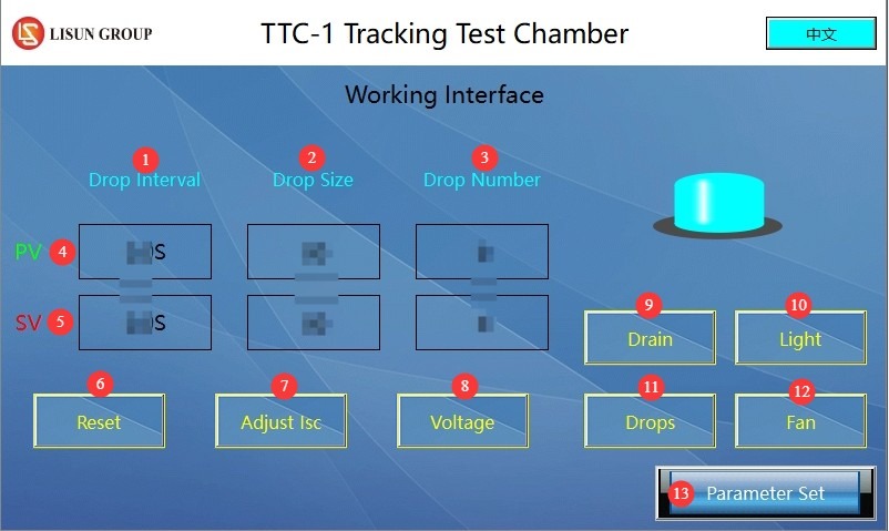
Gambar 6
3.2 Antarmuka Pengaturan Parameter
① Droplet size; ② Number of drops; ③ Interval between drops; ④ Alarm delay time.
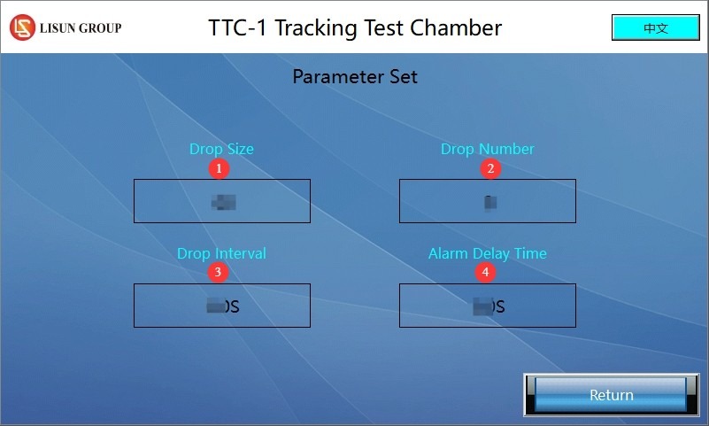
Gambar 7
4. Persiapan Sebelum Ujian
4.1 External Environment
Atur suhu lingkungan sekitar menjadi 23±2°C dan kelembapan relatif menjadi 50±5% untuk mencegah faktor lingkungan memengaruhi hasil pengujian. Catatan: Persyaratan suhu dan kelembapan untuk lingkungan penyimpanan peralatan berbeda dengan persyaratan untuk lingkungan pengoperasiannya.
4.2 Perlakuan Awal Sampel
The sample surface must be clean and free of contaminants such as dust, oil, and fingerprints. When cleaning, take care to avoid swelling, softening, or scratching the material;
Sample dimensions: ≥15 mm × 15 mm, thickness ≥3 mm; if the sample is too thin, multiple samples may be stacked (the number of layers must be recorded);
Special Procedures: If the sample surface is uneven, it may be polished (this must be noted in the test report) to prevent scratches from affecting the test results.
4.3 Debugging the Dropper
Preparation of the Electrolyte: Solution A (an ammonium chloride solution with a mass fraction of 0.1 ± 0.002%, having a resistivity of 395 ± 5 Ω·cm at 23°C) should be used preferentially; if strong etching is required, Solution B (containing 0.5% sodium alkyl sulfonate) may be selected.
Pour the prepared electrolyte into the dropper cup. You will need a container to catch the solution dripping from the needle. After turning on the device, press the “Purge” button on the touchscreen to remove air from the tubing and ensure continuous, uniform dripping.
4.4 Calibration of Electrodes and Specimens
4.4.1 Calibrating Electrode Pressure
For safety reasons, install the platinum electrodes with the power off, ensuring the dropper tip is oriented correctly and positioned exactly between the two electrodes. Check that the electrodes and counterweights are securely fastened. Adjust the counterweights so that, when the electrode support rod is level, the pressure on both electrodes is 1 N ± 5%, and then secure the counterweights.
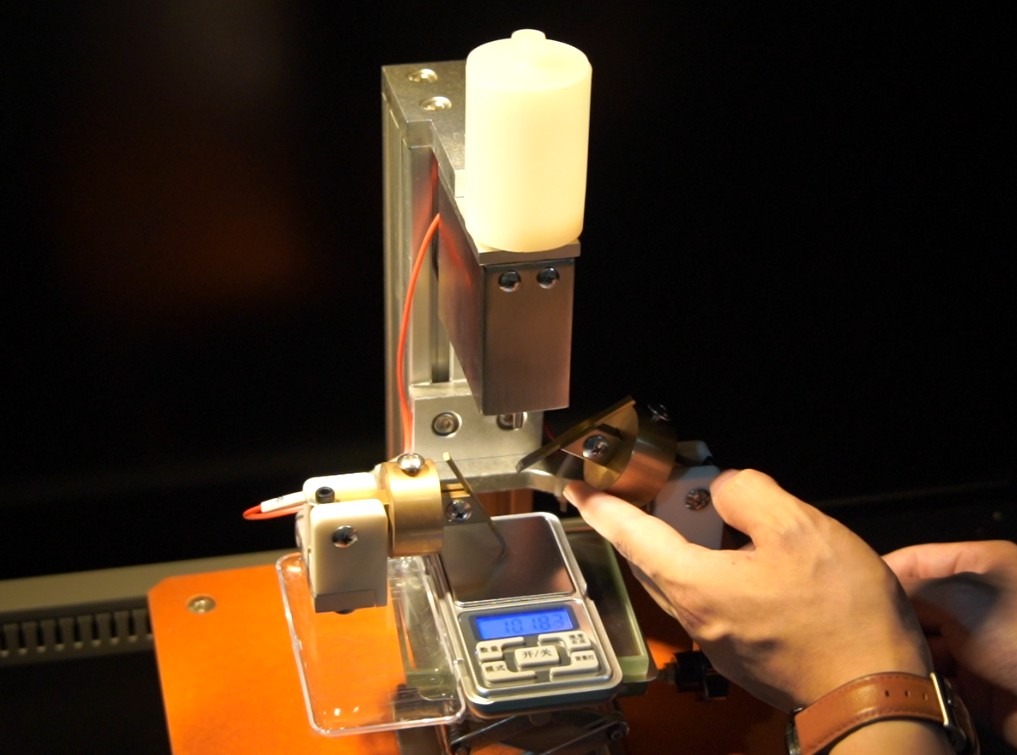
Gambar 8
Note: Under Earth’s gravitational conditions, 1 N is approximately equal to the gravitational force exerted by a mass of 102 g.
4.4.2 Installing the Test Specimen
Place the glass dish on the lifting tray, place the test specimen on top of the glass dish, position the two electrodes on the test specimen, and adjust the height of the tray so that the support rods of the two electrodes are horizontal and the distance between the electrodes is 4 ± 0.1 mm. The tip of the dropper should be 30–40 mm above the test specimen, as shown in the figure below:
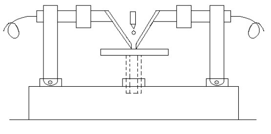
Gambar 9
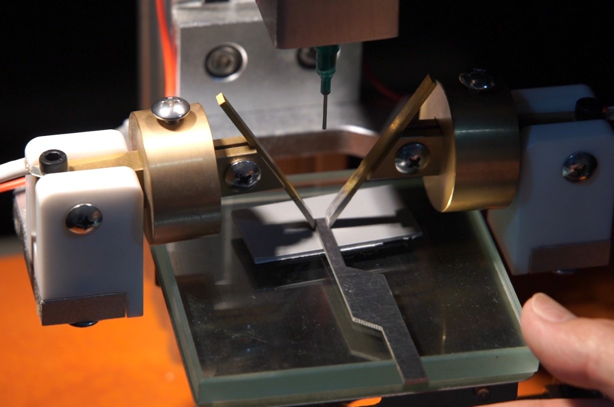
Gambar 10
5. Operating Procedure for the Tracking Test for Electrical Leakage
5.1 Debugging: Test Voltage and Maximum Short-Circuit Current
5.1.1 Debugging Test Voltage
Close the test chamber door securely. After turning on the unit, set the voltage range selector switch to the position closest to the test voltage, press the “Voltage Start” button on the touchscreen, and then slowly turn the “Voltage Adjustment” knob until the displayed voltage matches the required test voltage.
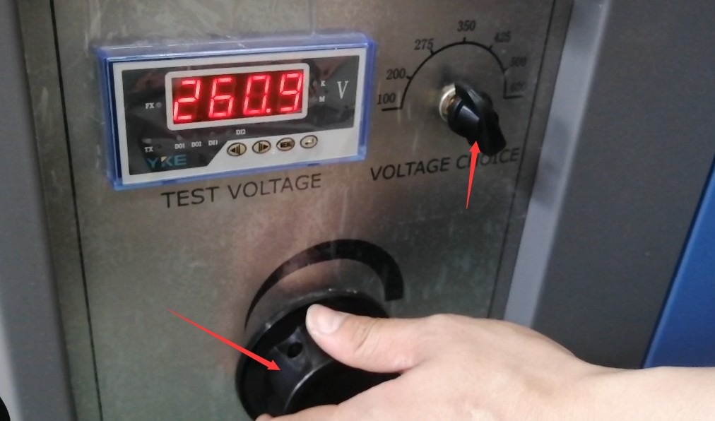
Gambar 11
In accordance with standard IEC 60112 (GB/T 4207), priority should be given to multiples of 25 V, such as 175 V, 250 V, 375 V, etc., for example, CTI testing begins at 300 V.
5.1.2 Short-Circuit Current Testing
First, turn the “Current Adjustment” knob to the minimum setting. With the “Voltage Start” button on the touchscreen still pressed, press the “Short-Circuit Current Calibration” button, then turn the “Short-Circuit Current Adjustment” knob until the ammeter reads 1.0 ± 0.1 A. When adjusting the short-circuit current, do not hold down the “Short-Circuit Current Debug” button for more than 2 seconds; press and release it repeatedly while observing the ammeter. If the short-circuit current exceeds 0.5 A and the “Short-Circuit Current Debug” button is held down for more than 2 seconds, the relay will activate, and the electrodes will be de-energized. If the short-circuit current has not been properly adjusted at this point, press the “Reset” button to reset the system, restart it, and readjust. Once the adjustment is complete, press the “Reset” button to exit debug mode.
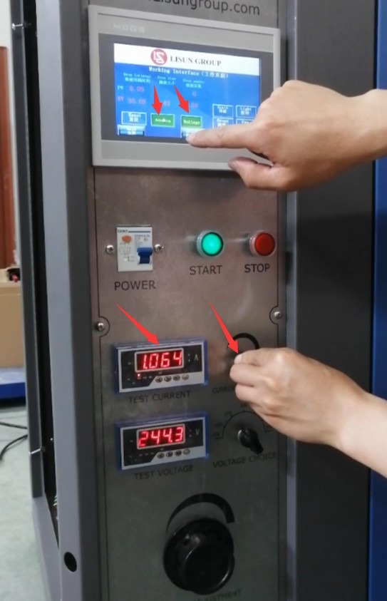
Gambar 12
5.2 Pengaturan Parameter Uji
Go to the parameter settings screen and configure the following settings in accordance with standard IEC 60112 (GB/T 4207):
Drop size: We calibrate the device to meet standards before shipment (the mass of 50 drops of solution must fall within the range of 0.997–1.147 g), so users do not need to make any adjustments;
Number of drops: 50 (the CTI test requires an additional 100 drops; the PTI test remains at 50 drops);
Interval between drops: 30 seconds;
Alarm delay: 2 seconds.
5.3 Melakukan Pengujian
Check once again to make sure the chamber door is closed and locked, the exhaust duct is unobstructed, and the electrodes are making good contact with the sample.
Press the “Voltage Start” button and verify that the voltmeter reading matches the set voltage; if there is a deviation, make a slight adjustment.
Press the “Dispense” button to start the test; the device will automatically dispense the electrolyte at the set intervals.
Real-time monitoring during the test through the observation window:
If a short-circuit current greater than 0.5 A occurs in the sample and persists for 2 seconds, the relay will automatically cut off the power supply, the equipment will sound an alarm, the sample will be deemed non-compliant, and the test will be terminated. Please click the “Reset” button to clear the alarm.
If the sample catches fire, immediately press the “Reset” button to manually terminate the test; the sample is deemed non-compliant.
If none of the above conditions occur, the device will continue to dispense drops until the set number of drops has been reached. Once dispensing is complete, the test ends normally, and the test specimen passes this test.
6. Prosedur Pasca-Ujian
6.1 Pengoperasian Peralatan Setelah Pengujian
6.1.1 Remove the test specimen
Turn on the fan to vent the smoke generated during the test, wait for the equipment to cool to room temperature (about 10 minutes), and wear protective gloves to remove the test specimen.
6.1.2 Electrolyte Treatment
If you will not be continuing the test that day, press the “Drain” button to completely drain any remaining electrolyte from the dropper cup and tubing.
Pour purified water into the drip cup, press the “Drain” button again, and repeat the flushing process 3 to 5 times to clean the solenoid valve and tubing and prevent corrosion.
6.1.3 Cleaning the Interior of the Equipment
Wipe down the interior of the test chamber, the electrode surfaces, and the trays with a clean cloth to remove any residual electrolyte and debris.
6.2 Recording and Organizing Experimental Data
Record key test data:
Sample Information: Material name, dimensions (thickness, length, width), pretreatment method; Test Parameters: Electrolyte type (A/B), test voltage, number of drips, interval between drips; Test Results: Presence of tracking, number of drops when a short circuit occurs, presence of combustion, whether the specimen perforated (perforation depth); Key Metrics: CTI (Comparative Tracking Index), PTI (Perforation Tracking Index), maximum erosion depth (accurate to 0.1 mm)
Data Organization Requirements: CTI Records: e.g., “CTI 400,” “CTI 375M” (where “M” indicates the use of Solution B), “CTI 400(350)” (the number in parentheses represents the maximum voltage at 100 drops); PTI Records: e.g., “PTI 250 passed,” “PTI 300M failed,” “PTI 275–1.2 passed” (the number indicates the etching depth); If the etching depth cannot be measured due to sample combustion, this must be noted in the record.
6.3 Persiapan Sampel
Remove the tested samples and inspect them for surface tracking, corrosion, perforations, and other conditions; take photographs for record-keeping (if necessary);
Remove loose debris and contaminants from the sample surface. If it is necessary to measure the erosion depth, use a depth gauge (with a 1-mm-diameter probe and a hemispherical tip) to measure at five points and record the maximum value;
After testing, samples must be sorted and stored or disposed of in accordance with environmental protection requirements to prevent environmental contamination;
If repeat testing is required, change the test location on the sample (spacing between locations must be ≥20 mm) or use a new sample.
6.4 Penyimpanan Peralatan
6.4.1 Persyaratan Penyimpanan Jangka Pendek
Storage Conditions: Dry, well-ventilated environment free of corrosive gases; temperature 5°C to 55°C; relative humidity ≤ 85%;
Equipment Status: Clean and dry; the electrodes must be wiped clean; there should be no residual liquid in the dropper tubing.
6.4.2 Persyaratan untuk Penyimpanan Jangka Panjang
Before storage, thoroughly clean the equipment—especially the dosing system and electrodes—to ensure there are no electrolyte residues. Cover the equipment with a dust cover to prevent dust from entering the interior. Tidy up the power cord to prevent it from being crushed or damaged.
Disconnect all connecting cables (power cord, exhaust hose), and pack and store the accessories (electrodes, gauges, electronic scales, etc.) separately to prevent loss or damage. If the electrodes are to be stored for an extended period, they must be sealed to protect them from moisture.
Regularly inspect the storage environment to prevent damage from moisture, high temperatures, or pests; turn on the equipment for half an hour each month to check its condition.
7. Pemecahan Masalah dan Penyelesaian Masalah Umum
7.1 Dispensing System Malfunction
| Gejala Kesalahan | Kemungkinan penyebab | Prosedur |
| Discontinuous dispensing or no dispensing | Clogged tubing, clogged drip needle | Rinse the tubing with clean water and use a fine needle to clear the needle tip (to avoid damaging the needle). |
| Inaccurate drop volume | The liquid level in the dropper cup is too low, and there is air in the tubing. | Refill the electrolyte, then press the “Drain” button to release any air. |
| Uneven droplet intervals | Solenoid valve malfunction, incorrect parameter settings | Check the parameter settings; if the solenoid valve is malfunctioning, contact the manufacturer for repairs. |
7.2 Voltage-Related Faults
| Gejala Kesalahan | Kemungkinan penyebab | Prosedur |
| Voltage Failure to Start | Power not connected, poor grounding, cabinet door not closed properly | Check the power supply and grounding, and close the cabinet door to ensure it is locked securely. |
| The voltage cannot be adjusted to the set value | Unstable power supply voltage, incorrect voltage setting selection | Turn on the regulated power supply and reselect the appropriate voltage setting. |
| Excessive voltage fluctuations | Power supply interference, poor electrode contact | Stay away from sources of interference and check that the electrodes are securely connected. |
7.3 Current-Related Faults
| Gejala Kesalahan | Kemungkinan penyebab | Prosedur |
| Unable to adjust the short-circuit current | Fault in the Current Adjustment Knob | Check to see if the knob is stuck |
| Unstable short-circuit current | The debug button is held down for too long; there is a loose connection in the circuit. | Press for no more than 2 seconds per press as instructed, and check the circuit connections. |
| The relay does not operate | Current detection circuit malfunction, incorrect alarm delay parameters | Contact Us for Circuit Repair |
7.4 Kerusakan Lainnya
| Gejala Kesalahan | Kemungkinan penyebab | Prosedur |
| The touchscreen is unresponsive | Power Not Connected, Screen Frozen | Unplug the device and restart it. If it still does not respond, the screen needs to be repaired. |
| Smoke cannot be vented from the test chamber | Clogged exhaust duct, fan malfunction | Clean the exhaust duct and check that the fan is operating properly. |
| The electrode pressure does not meet the requirements. | Loose weights, deformed electrode brackets | Re-secure the counterweight and level the electrode holder. |
| The sample catches fire frequently | Test voltage is too high; the specimen has poor resistance to tracking | Reduce the test voltage to verify whether the sample meets the test requirements. |