
 Inggris
 中文简体
中文简体 Русский
 Español
 Português
 Türkçe
 العربية
 Deutsch
 Polski
 Italiano
 Français
 한국어
한국어 ไทย
ไทย Tiếng Việt
 日本語
日本語





























Generator Uji Impuls
Pengguna manual
berlaku LISUN Model: SUG255,SUG255CX,SUG255LX,SUG255MX,SUG255PX,SUG255PX-20KV、SUG255PX-25KV,SUG255PX-30KV,SUG255PX-50KV、SUG255XX、SUG335
1. Membuka Kemasan dan Mengenal Peralatan Secara Dasar
1.1 Spesifikasi Teknis Utama
SUG255 Seri:
| LISUN Pilih Model | SUG255LX | SUG255MX | SUG255PX | SUG255PX-20KV | SUG255PX-25KV | SUG255PX-30KV |
| Rentang Tegangan Output | 0–12 meter persegi | 0–20 meter persegi | 0–25 meter persegi | 0–30 meter persegi | ||
| Generator Internal Resistance | 12 Ω dan 500 Ω | 38 Ω dan 500 Ω | 2 Ω dan 500 Ω | |||
| Bentuk Gelombang Tegangan Output | 1.2 / 50 μs | |||||
| Polaritas Tegangan Keluaran | Positif atau negatif | |||||
| Instruksi Operasi | Manual atau Otomatis | |||||
| Jumlah pengukuran | 1-9999 | |||||
| Selang | 3–9999 detik | |||||
SUG335 Seri:
| Kategori Parameter | Spesifikasi Spesifik |
| Lightning Strike Waveform Rise Time | 1.2 µs ± 30% |
| Half-value time of a falling waveform | 50 µs ± 20% |
| Surge Voltage Range | 1–12.5 kV, accuracy ≤ ±3% |
| Output Impedance | 42 Ω |
| Surge Interval | 1–99 s (configurable; complies with the requirements of Clause 14 on page 43 of IEC 60335:2010+A1:2013) |
| Jumlah lonjakan | 1–9999 times (configurable) |
| Polaritas Lonjakan | Positive terminal, negative terminal |
| Waveform Detection | Features a built-in high-voltage probe that can be paired with the OSP1102 Digital Oscilloscope for waveform detection |
1.2 Membuka Kemasan dan Memeriksa Isinya
1.2.1 Membuka Kemasan dan Pemeriksaan Visual
Saat membuka kemasan perangkat, tangani dengan hati-hati untuk menghindari goresan pada casing dengan alat tajam. Setelah membuka kemasan, periksa terlebih dahulu bagian luar perangkat untuk memastikan tidak ada deformasi atau penyok yang terlihat, dan tombol-tombolnya tidak rusak atau longgar.
If you find that any equipment or accessories are damaged or deformed, do not turn on the power. Please contact us immediately.
1.2.2 Unit Utama dan Aksesoris
Main Unit Category: 1 SUG Impulse Test Generator.
Standard Accessories: ① Power cord; ② Ground wire, used to connect to the PGND protective ground terminal; ③ Coaxial cable, used to connect to an external oscilloscope for monitoring surge waveforms; ④ Discharge tube, used to check whether the equipment is outputting a surge in the event of a malfunction; ⑤ EUT test lead, used to connect the Surge Generator to the test specimen.
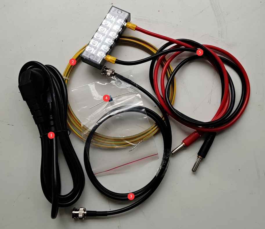
Gambar 1
Download links for the electronic user manual, warranty card, and other documents have been sent to you via email. Please download them as soon as possible. If you missed the email, please feel free to contact us to request the download links again.
2. Tindakan Pencegahan Keamanan
2.1 Pedoman Penempatan
Ensure the ambient temperature is between 15°C and 35°C, relative humidity is between 10% and 60% (no condensation), and atmospheric pressure is between 86 kPa and 106 kPa. Avoid high-voltage short circuits or damage to the equipment caused by moisture;
The premises must be free of strong electromagnetic interference, corrosive gases, flammable and explosive materials, and dust, and must be well-ventilated to prevent sparks from causing hazards;
Place it on a stable workbench; avoid tilting or inverting it, and keep it away from sources of vibration;
The equipment must be placed at least 1000 mm away from walls and surrounding structures (such as other testing equipment and shelving) to facilitate maintenance; at least 2000 mm of space must be left in front of the equipment to ensure smooth operation and that there are no obstructions in the surrounding area.
2.2 Standar Keselamatan Tegangan Tinggi
2.2.1 Pemeriksaan Keamanan
Verify that the equipment’s power supply voltage matches the mains voltage (AC 220 V ±10%, 50/60 Hz), and confirm that the power supply is properly grounded and that the grounding wire is free of damage or looseness;
Grounding Requirements: The main unit’s protective grounding terminal (PGND) must be connected to the ground, with a grounding resistance of ≤4 Ω, to ensure safe discharge of high voltage;
Operator harus memiliki tangan yang kering dan tidak boleh mengenakan perhiasan logam apa pun.
2.2.2 Persyaratan Keselamatan untuk Prosedur Operasional
Operators must undergo professional training and be familiar with this manual and the relevant standards. Non-professionals are prohibited from operating or disassembling the equipment. The equipment contains high-voltage circuits; opening the cover may pose an electric shock hazard. Contact the manufacturer’s technical staff for repairs.
The equipment generates high-voltage, high-current surges during operation. Do not touch the pulse output connector or the EUT test specimen connections under any circumstances.
During testing, unauthorized personnel are prohibited from remaining within 1 meter of the EUT to prevent accidental electric shock or interference from electrical discharges.
Sebelum mengganti sambungan atau mengganti EUT, Anda harus terlebih dahulu memastikan bahwa output tegangan tinggi dimatikan (lampu indikator HV mati) dan menunggu setidaknya 5 menit untuk memastikan bahwa kapasitor tegangan tinggi internal telah sepenuhnya habis dayanya.
Do not eat or drink during the test to prevent accidents caused by electric shocks.
When multiple people are involved, roles must be clearly defined, and everyone must confirm their tasks with each other before testing begins to avoid errors.
2.3 Langkah-langkah Tanggap Darurat
In the event of an electric shock: Immediately shut off the main power to the equipment, move the operator to a safe area, administer first aid if necessary, and contact medical personnel.
Equipment Malfunction (Smoke, Unusual Noises, Unusual Odors): Immediately turn off the equipment and disconnect the power supply; disconnect all cables; do not turn the equipment back on; contact the manufacturer for repairs.
Keluaran lonjakan abnormal: Hentikan pengujian, hubungi produsen untuk pemecahan masalah, dan jangan sentuh port pengujian secara langsung dengan tangan Anda.
2.4 Lainnya
Untuk hal-hal yang tidak tercakup dalam panduan ini, harap berhati-hati atau hubungi kami.
3. Operating Procedures for Pulse Withstand Voltage Testing
3.1 Pengkabelan Peralatan
3.1.1 Pengenalan Panel Belakang dan Pengkabelan
① Power cord; ② Remote control (reserve port; if not specified at the time of purchase, this feature is not available); ③ Ground wire. Please refer to Section 2.2.1 for connection instructions.
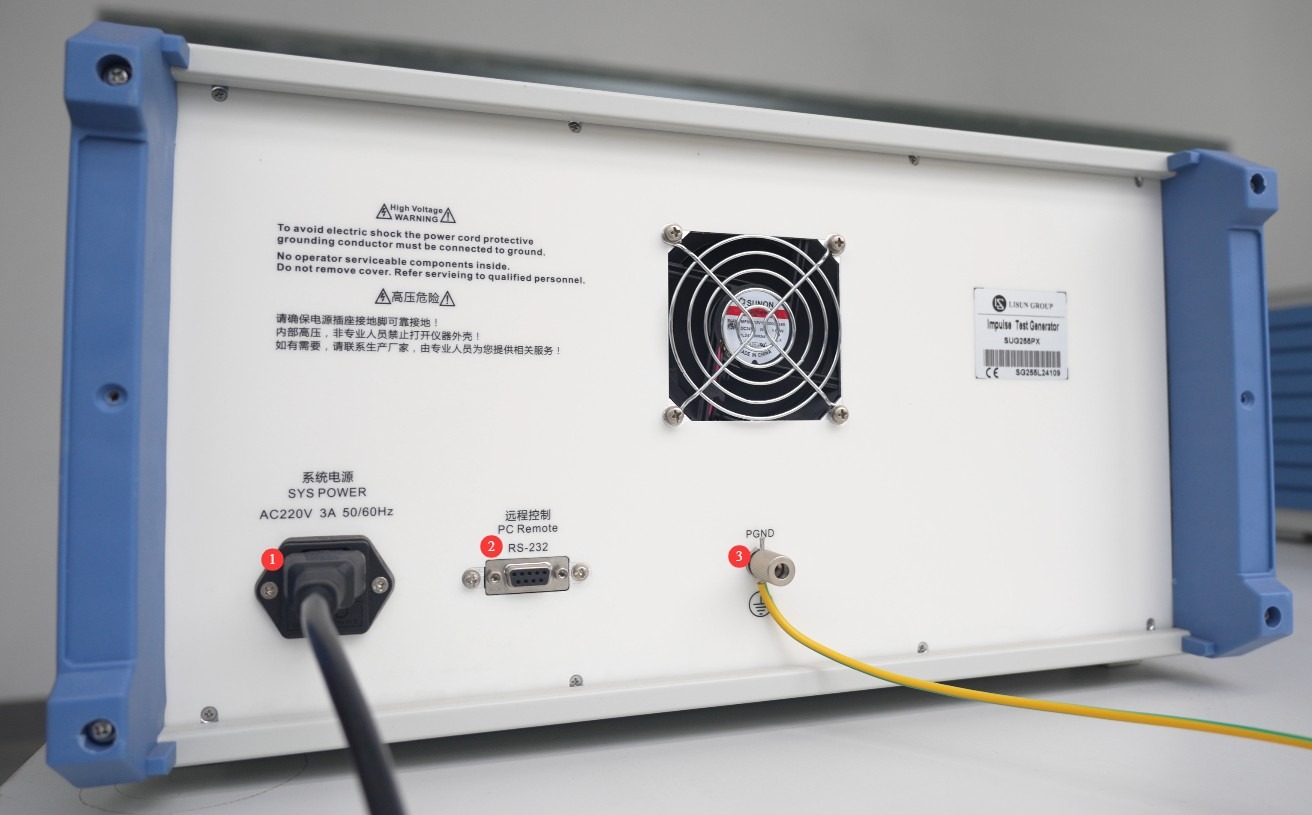
Gambar 2
3.1.2 Front Panel Overview and Wiring
① Power switch; ② Touchscreen; ③ EUT connection cable, with one end connected to the required impedance and the other end connected to the EUT’s high-voltage test terminal; ④ EUT connection cable, with one end connected to the COM port and the other end connected to the EUT’s ground terminal or low-potential terminal;⑤ Place the EUT on the left side of the withstand voltage tester; do not route the EUT connection cable in front of the touchscreen to avoid interfering with the touchscreen during testing; ⑥ CRO-V oscilloscope interface, which can be used to connect an external oscilloscope to monitor waveforms; ⑦ USB port, which can be used to connect a mouse or to update the software.
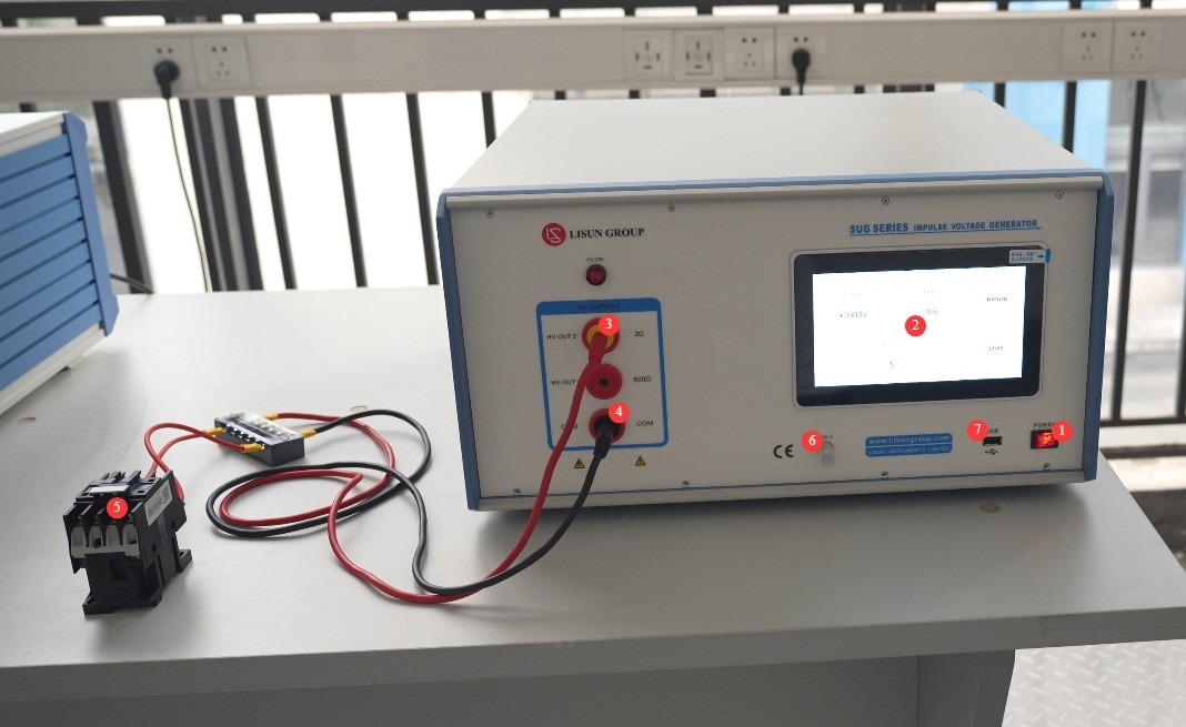
Gambar 3
3.2 Introduction to the Touchscreen Program and Parameter Settings
① General Precautions for Use (Functionality is not yet fully developed; do not perform any operations at this time); ② System Information Screen; ③ Switch Between Chinese and English; ④ Pulse Withstand Voltage Test Screen.
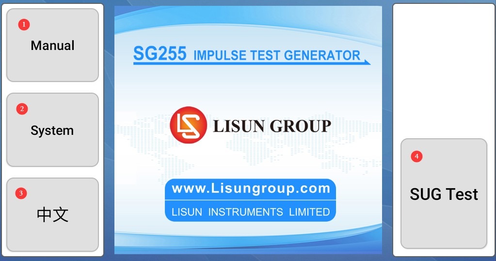
Gambar 4
① Test voltage and polarity settings; ② Interval time settings; ③ Number of test cycles; ④ Back; ⑤ Start/Stop test.
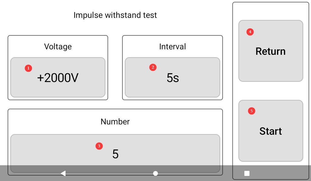
Gambar 5
3.3 Memulai Pengujian
After confirming that the wiring and parameter settings are correct, click “Start” to begin the test; the HV (High Voltage) indicator light will turn on.
① Set the voltage and display the current voltage; ② Countdown timer for the interval; ③ Total number of tests and current test number; ④ Tap to manually stop the current test.
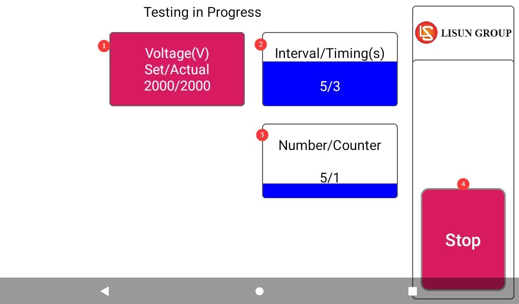
Gambar 6
4. Prosedur Pasca-Ujian
4.1 Tes Dihentikan
Jika EUT (Equipment Under Test) terlihat rusak selama pengujian, segera ketuk “Hentikan Pengujian” pada layar sentuh.
If no errors occur during the test, wait for the test to end automatically.
Wait 5 minutes to ensure that the high-voltage capacitors inside the main unit have fully discharged, then replace the EUT for testing, or turn off the main unit’s power.
4.2 Pengorganisasian dan Pembersihan Pasca-Tes
Verifikasi apakah EUT telah lulus uji (tidak ada penurunan kinerja, tidak ada kerusakan).
Bersihkan area pengujian dan lap dengan kain kering. Jangan gunakan alkohol atau bahan pembersih korosif.
The pulse withstand voltage test is a destructive test; it does not automatically generate a test report, but the device automatically saves the test data. You can go to the “System Information” screen, click “Test Log,” and export the corresponding test data to a USB flash drive via the USB port. The exported file is in TXT text format.
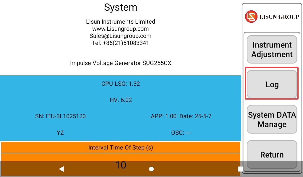
Gambar 7
4.3 Penyimpanan Peralatan
4.3.1 Persyaratan Penyimpanan Jangka Pendek
Jika peralatan tersebut digunakan setiap hari, tidak diperlukan tindakan lebih lanjut setelah pembersihan selesai dilakukan setelah setiap pengujian.
4.3.2 Persyaratan Penyimpanan Jangka Panjang
If the device will not be used for an extended period (more than 1 month), please disconnect all cables and cover the device with a dust cover to prevent dust buildup.
Perangkat ini sebaiknya dinyalakan sekali sebulan selama setengah jam saja untuk mencegah komponen listrik (seperti kapasitor dan kontaktor) mengalami kerusakan.
5. Gunakan perangkat eksternal untuk memverifikasi keluaran lonjakan arus.
5.1 Using an External Oscilloscope (Using the LISUN Osiloskop Seri OSP sebagai Contoh)
5.1.1 Menggunakan Port CRO
Set the following parameters on the Impulse Test Generator: Set the voltage to +1 kV; set the interval as short as possible, such as 5 seconds; and set the number of surges to a higher value to make it easier to view each waveform.
Do not connect any EUT; ensure that the circuit is completely open. Then, use the coaxial cable provided to connect the “CRO-V” port of the Impulse Test Generator to the oscilloscope.
Tekan tombol ① “Menu” di bawah ② “Pemicu.”
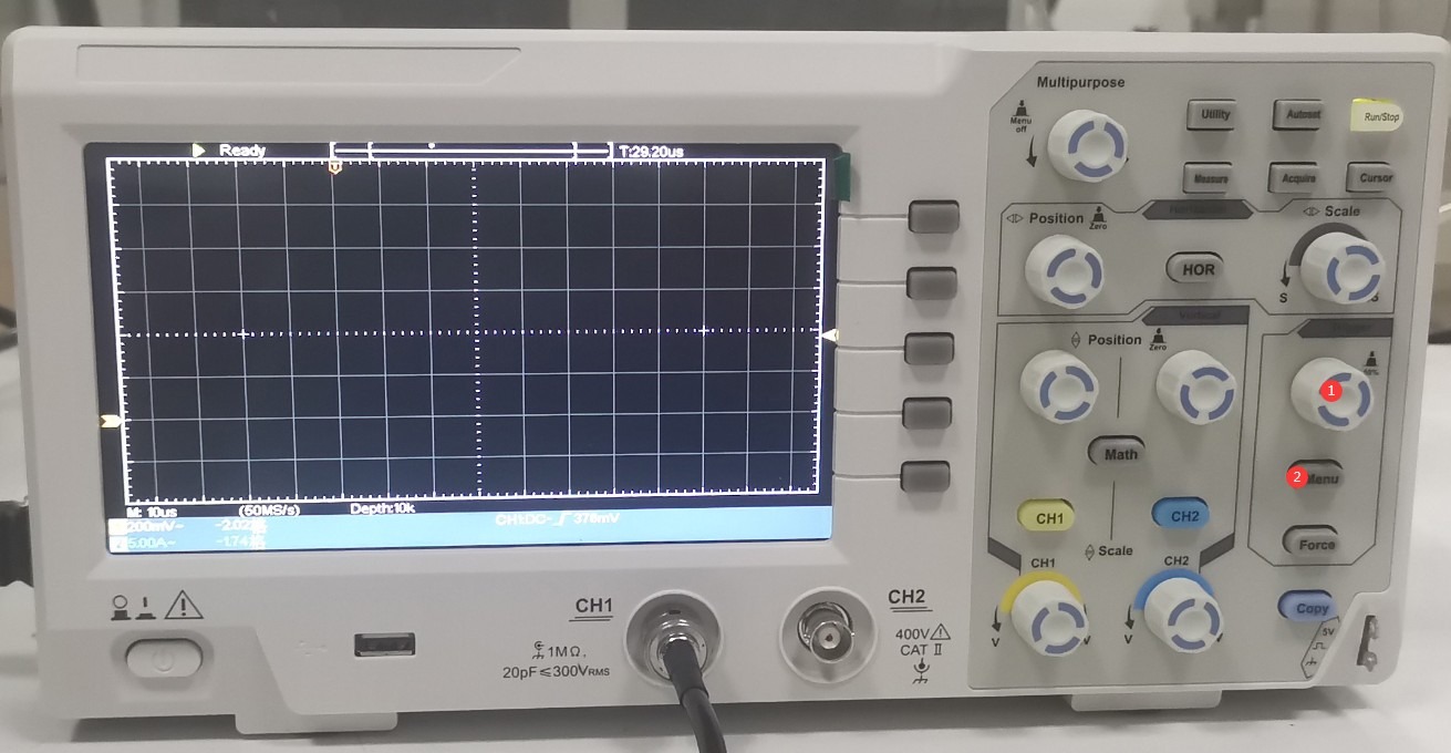
Gambar 25
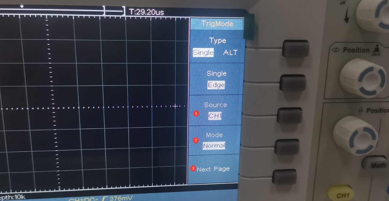
① Pilih saluran yang terhubung, ② atur mode pemicu ke “Normal,” ③ klik untuk melanjutkan ke halaman berikutnya.
Gambar 26
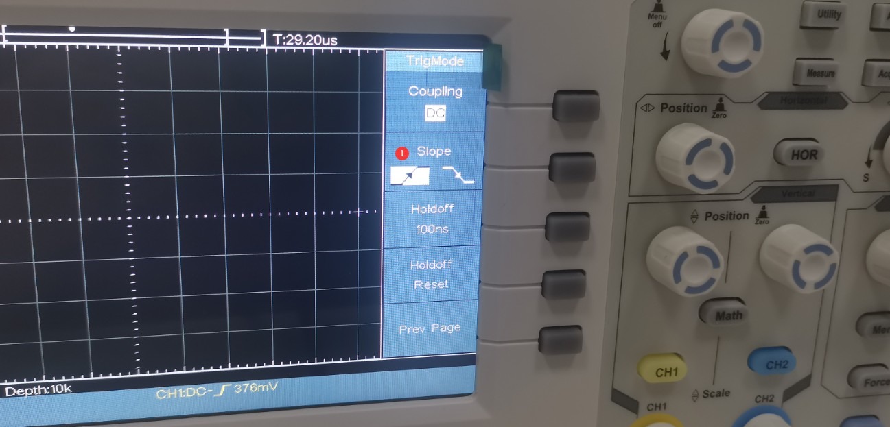
① Pilih tepi naik.
Gambar 27
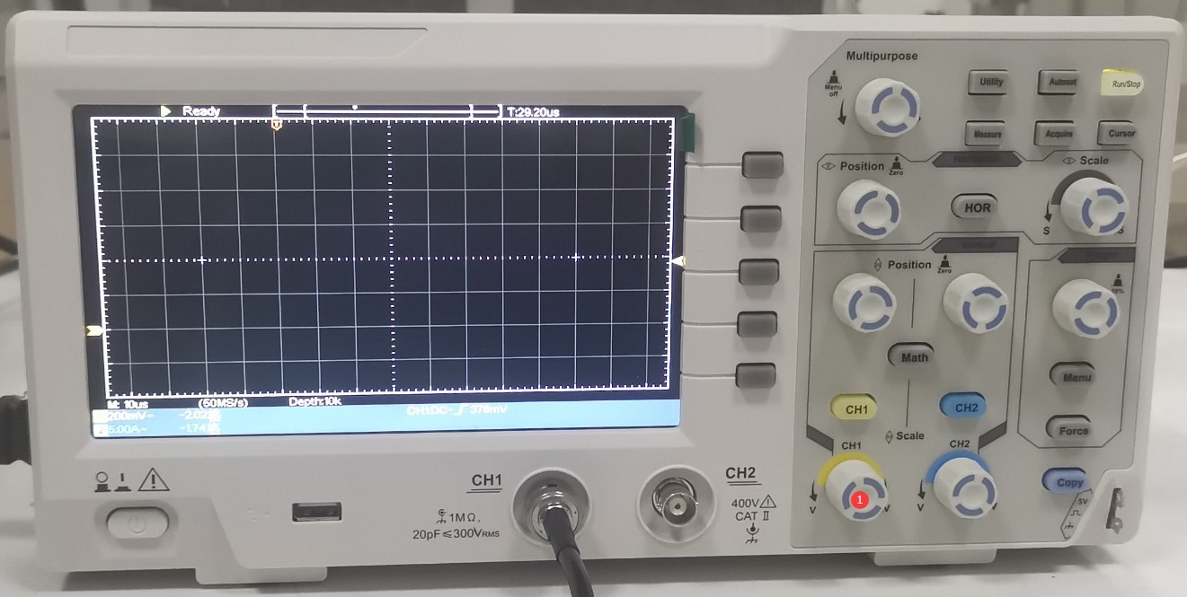
Tekan kenop CH1 (①).
Gambar 28
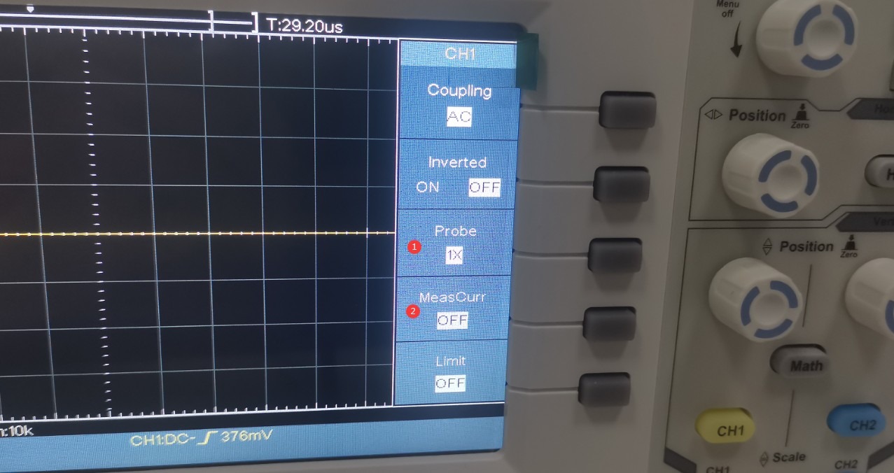
① Pilih pengali 1X; ② Matikan fungsi pengujian saat ini.
Gambar 29
The Impulse Test Generator has a built-in 1000:1 high-voltage Voltage Probe at the CRO interface. If the surge voltage is set to +1 kV, the actual voltage reaching the oscilloscope is 1 V. Turn the ① CH1 knob to set the ② vertical axis of the oscilloscope to 1/5 per division, or 200 mV, which makes it easier to view the entire waveform. Turn the ③ “Scale” knob to set the ④ horizontal time axis of the oscilloscope to 10 μs per division.
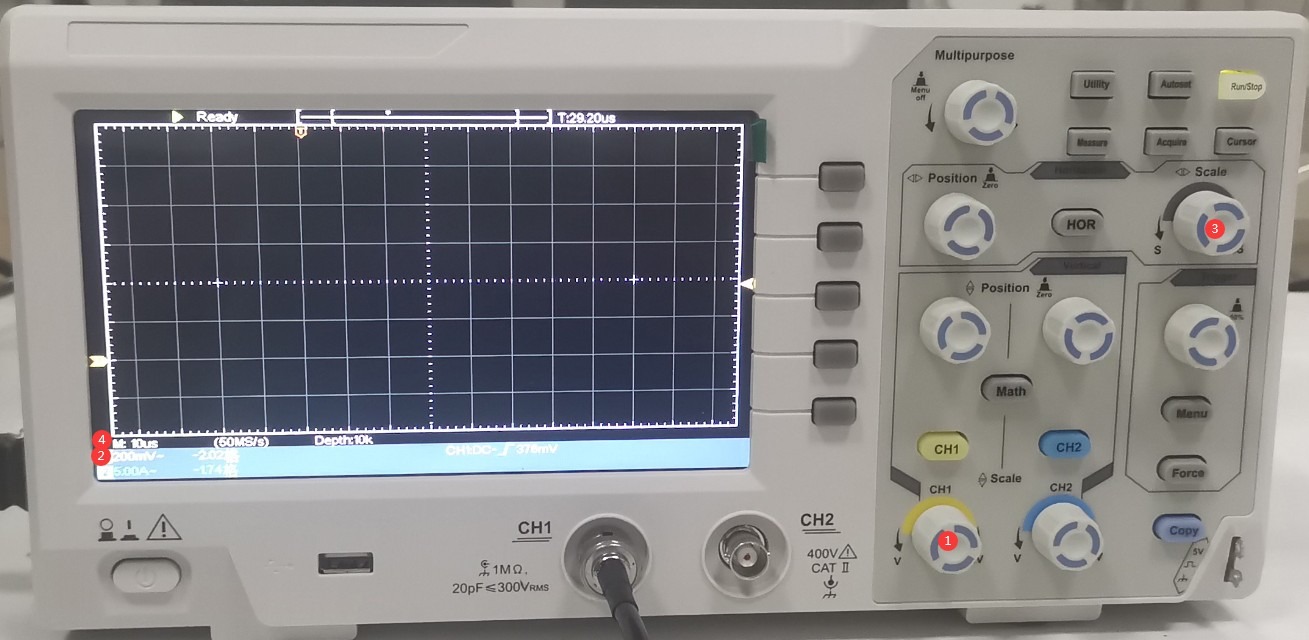
Gambar 30
Turn the two knobs—① (left/right) and ② (up/down)—to adjust the position of the waveform display to the appropriate location shown in the figure. Turn the ③ “Trigger” knob to adjust the level to approximately the middle position.
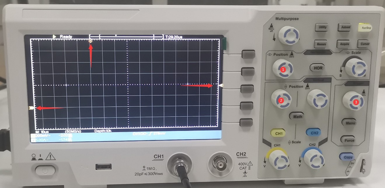
Gambar 31
On the touchscreen of the Impulse Test Generator, tap “Start” to begin the test. Each time a pulse is output, the oscilloscope will display a surge voltage waveform as shown in the figure below. Use the horizontal cursor to verify the output voltage; since it is set to 1 kV, the oscilloscope should display 1 V.
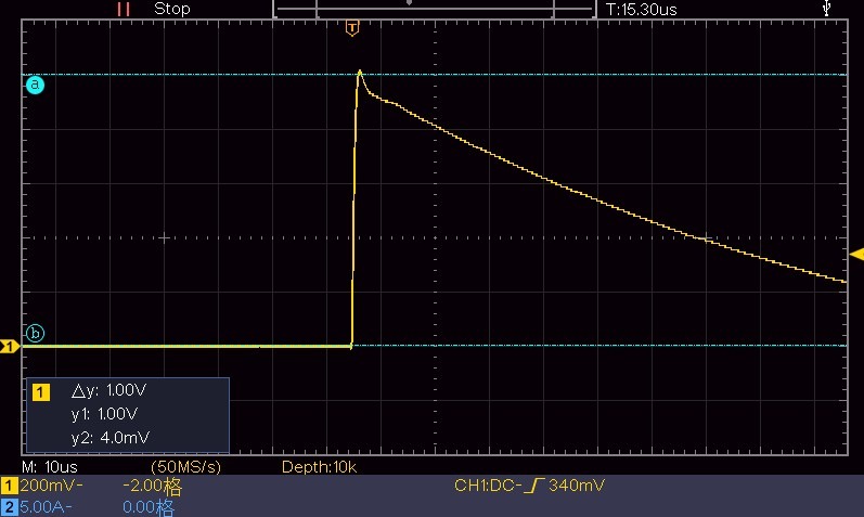
Gambar 32
Gunakan kursor vertikal untuk memastikan waktu setengah lebar gelombang.
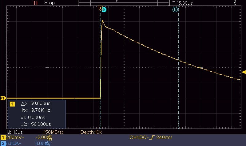
Gambar 33
Atur skala waktu ke 1 μs, biarkan semua pengaturan lainnya tidak berubah. Tunggu keluaran lonjakan berikutnya, lalu gunakan kursor vertikal untuk menentukan waktu naik lonjakan tersebut.
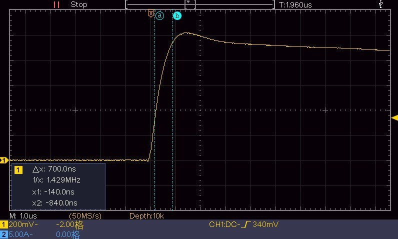
Gambar 34
5.1.2 Connecting to the EUT Port
Connecting an external oscilloscope to the CRO port is intended solely for the user’s convenience when viewing waveforms. However, if the device needs to be calibrated, you must provide your own high-voltage probe and connect the oscilloscope directly to the EUT connection port on the front panel of the impulse withstand voltage tester. Refer to Section 5.1.1 and the scaling factor of the high-voltage probe being used when operating the oscilloscope.
5.2 Menggunakan Tabung Pembuangan
Tabung pelepasan dapat digunakan untuk memverifikasi dengan mudah apakah suatu perangkat menghasilkan lonjakan tegangan.
Connect the discharge tube to the pulse withstand voltage tester as the EUT. Set the output voltage to 12 kV, then click “Start” to begin the surge test. The discharge tube will flash the moment the pulse is output; please dim the lights in the room to facilitate observation. See the figure below:
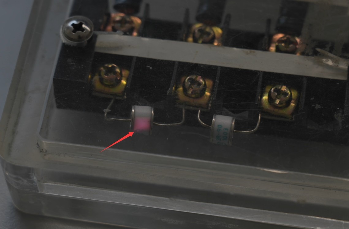
Gambar 35
Ini memastikan bahwa perangkat memang menghasilkan lonjakan daya keluaran. Jika tabung pelepasan tidak berkedip, silakan hubungi layanan pelanggan.
6. Pemecahan Masalah dan Penyelesaian Masalah Umum
6.1 Perangkat tidak mau menyala
Gejala: Setelah menyalakan sakelar daya, perangkat tidak merespons (lampu indikator tidak menyala, dan kipas tidak berputar).
Kemungkinan penyebabnya: ① Kabel daya tidak terhubung dengan benar atau rusak; ② Tegangan suplai tidak normal; ③ Sekring putus; ④ Varistor (MOV) terbakar.
Troubleshooting: Ensure the power cord is intact and securely connected. Power supply issues—such as unstable voltage, excessively high voltage, or harmonic interference—can cause the fuse or varistor to burn out. It is recommended to use a voltage-stabilized, clean sine-wave AC power supply to power the device. Replace the fuse or varistor with one of the same type.
Gambar di bawah ini menunjukkan lokasi sekering:
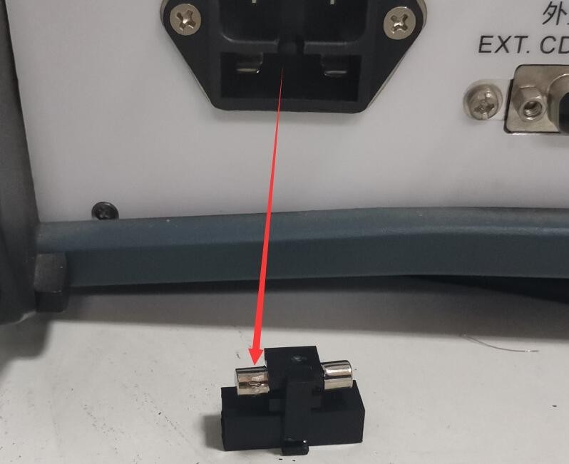
Gambar 39
Gambar di bawah ini menunjukkan lokasi varistor (MOV) di dalam catu daya yang telah difilter:
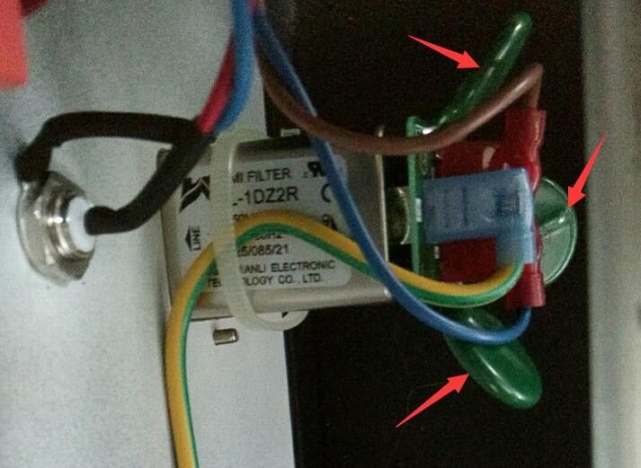
Gambar 40
6.2 Restart Perangkat Otomatis
Symptom: The device automatically restarts during pulse output.
Possible cause: The ground wire is not properly connected.
Solusi: Lihat Bagian 2.2.1. Hubungkan terminal pentanahan PGND di bagian belakang host ke ground, dan pastikan resistansi pentanahan ≤4Ω; jika tidak, tegangan tinggi mungkin tidak dapat dibuang dengan aman, menyebabkan perangkat secara otomatis memulai ulang.
6.3 Bentuk gelombang mengandung interferensi
Symptom: When using an external oscilloscope connected to the CRO port to inspect a standard surge waveform, some noise appears when the waveform is magnified. See the figure below:
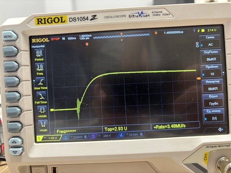
Gambar 41
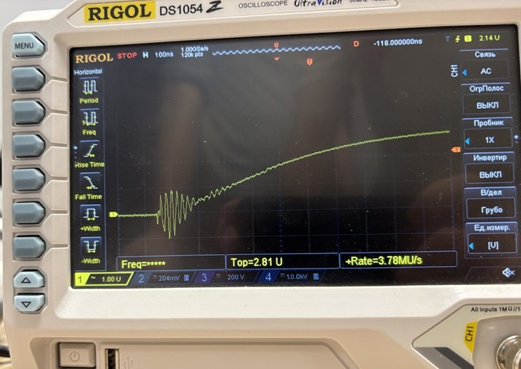
Gambar 42
Kemungkinan penyebab: Osiloskop digital dan port CRO bawaan dirancang untuk memudahkan pengguna memperoleh data bentuk gelombang dengan cepat dan mudah, tetapi mungkin menghasilkan sedikit noise.
Procedure: If you need to obtain the actual output waveform of the surge generator, or if you wish to calibrate the equipment, use an oscilloscope and a high-voltage probe to directly inspect the waveform at the EUT connection port, as shown in the figure below:
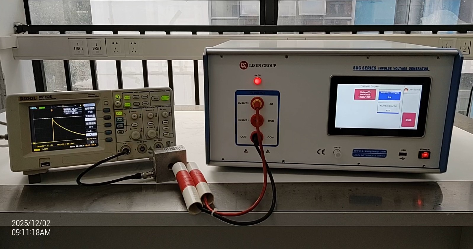
Gambar 43