
 Inggris
 中文简体
中文简体 Русский
 Español
 Português
 Türkçe
 العربية
 Deutsch
 Polski
 Italiano
 Français
 한국어
한국어 ไทย
ไทย Tiếng Việt
 日本語
日本語





























Mesin Uji Sulfur Dioksida
Pengguna manual
berlaku LISUN Model: SQ-010,SQ-016,SQ-020,SQ-150,SQ-250,SQ-750
1. Pemahaman Dasar tentang Peralatan
1.1. Tinjauan Produk
1.1.1. Model Differentiation
| LISUN Pilih Model | Dimensi Kerja (mm) | Dimensi Eksternal (mm) | Power Supply Voltage | Daya |
|---|---|---|---|---|
| SQ-150 | 450 600 × × 400 | 800 1070 × × 1050 | AC 220 V. | 2.5 kW |
| SQ-250 | 600 900 × × 500 | 870 1400 × × 1150 | 3 kW | |
| SQ-750 | 750 1100 × × 500 | 1030 × 1680 × 1260 | 4 kW | |
| SQ-010 | 850 1300 × × 600 | 1160 2000 × × 1390 | AC 380 V. | 6 kW |
| SQ-016 | 850 1600 × × 600 | 1280 2320 × × 1500 | 7.5 kW | |
| SQ-020 | 900 2000 × × 600 | 1220 2530 × × 1410 | 9 kW |
1.1.2. Ruang Lingkup Penerapan
The SQ Series Sulfur Dioxide Test Machine is a testing device developed by LISUN specifically for simulating industrial corrosive environments. Its core function is to simulate the corrosive environment of an industrial atmosphere containing sulfur dioxide (SO₂) by precisely controlling the concentration of SO₂ gas and the test temperature. This accelerates the evaluation of the resistance to sulfidation corrosion of metallic materials, plating, coatings, and complete products, enabling the rapid identification of material protection defects or flaws in product structural design, and providing a scientific basis for verifying the corrosion resistance of industrial equipment, building materials, hardware products, and electronic components.
1.2. Verification of Test Chamber Configuration
1.2.1. Membongkar
When unpacking the equipment, handle it gently to avoid subjecting the main unit to external impacts. After unpacking, first inspect the equipment casing, the glass door of the mist chamber, the touchscreen, and other components for any damage, deformation, or scratches.
Check all equipment connections (power connection, air intake connection, exhaust connection, drain connection, etc.) to ensure they are in good condition and free of looseness, blockages, or damage.
If you notice any damage or deformation to the equipment or accessories, Jangan menyalakan daya.; kontak LISUN Layanan pelanggan segera.
1.2.2. Main Unit and Accessories
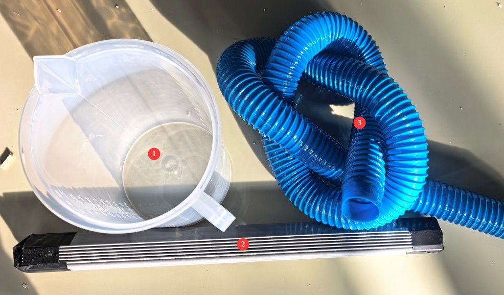
SQ Series Sulfur Dioxide Test Machine: 1 unit.
See Figure 1-1 for other major components.
| Jumlah | Note |
|---|---|
| ① | Silinder Lulus |
| ② | Sample holders, V-grooves, and O-shaped rods |
| ③ | Pipa knalpot |
2. Tindakan Pencegahan Keamanan
2.1. Keamanan Lingkungan
2.1.1. Persyaratan Instalasi
Suhu lingkungan: 5–25°C. Hindari suhu yang terlalu tinggi, karena dapat memengaruhi stabilitas kontrol suhu ruang uji, dan suhu yang terlalu rendah, karena dapat memengaruhi efisiensi pemanasan.
Kelembaban relatif: ≤85% RH. Lingkungan harus kering untuk mencegah korsleting pada komponen listrik peralatan yang disebabkan oleh kelembapan.
Standard atmospheric conditions: atmospheric pressure ranges from 86 to 106 kPa at altitudes between 0 and 2000 meters.
Other requirements: No direct sunlight; no strong electromagnetic fields (such as those from Voltage Transformers or large electric motors, to avoid interfering with the control system); no strong air currents (such as air blowing directly from an air conditioning vent).
2.1.2. Persyaratan Ruang
The equipment must be placed on a level surface; use a level to ensure the unit is stable.
Allow sufficient space around the equipment: ≥1500 mm on the left, right, and rear sides (to facilitate piping and cable connections, liquid refills, and maintenance), and ≥2000 mm in front (to allow access to the control panel door and touchscreen).
2.2. Keamanan Listrik
2.2.1. Koneksi Daya
Model kecil (SQ-150, SQ-250): 220V single-phase power, power rating below 3.0 kW; requires a single 1.5 mm² wire;
Medium-sized model (SQ-750): 220 V single-phase power, 3.5 kW, requires a single 2.5 mm² wire;
Model besar (SQ-010, SQ-016, SQ-020): 380V, three-phase, five-wire system; power rating greater than 5 kW; wiring requires a single 2.5 mm² conductor.
Power outlets must comply with safety standards, provide proper grounding, and have a rated current that matches the device’s power rating (it is recommended to install a separate circuit breaker).
2.2.2. Grounding Specifications
Grounding must be performed in accordance with standards, with a grounding resistance of ≤4 Ω. A dedicated grounding wire (with a cross-sectional area of at least 2.5 mm²) must be used to connect to the ground.
Sangat dilarang menghubungkan kabel ground ke pipa gas, pipa air non-logam, pipa pemanas, atau fasilitas yang mudah terbakar atau meledak lainnya untuk menghindari risiko sengatan listrik atau kebakaran.
2.3. Safety Precautions for the Use of Sulfur Dioxide
Throughout the entire procedure, you must wear a gas mask (SO₂-resistant), acid- and alkali-resistant gloves, and safety goggles. Direct contact with test specimens after testing with bare hands is strictly prohibited.
Do not open the cabinet lid during the test run to prevent sulfur dioxide gas from escaping and causing respiratory irritation.
If you accidentally inhale sulfur dioxide and feel unwell, move to fresh air immediately; if symptoms are severe, seek medical attention promptly.
Check the air line seals regularly; apply soapy water to the joints to see if any bubbles appear.
2.4. Lain
Untuk hal-hal yang tidak tercakup dalam panduan ini, harap berhati-hati atau hubungi kami.
3. Introduction to the Test Chamber
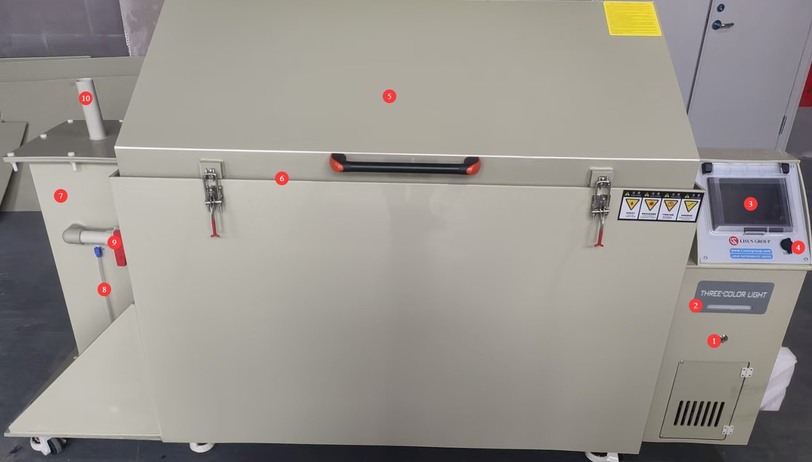
3.1. Front of the Test Chamber
Lihat Gambar 3-1.
| Jumlah | Note |
|---|---|
| ① | Saklar daya |
| ② | Three-color indicator lights: yellow for standby, green for operation, and red for an alarm |
| ③ | Touchscreen |
| ④ | USB port, which can be used for future software updates |
| ⑤ | Test Chamber Lid |
| ⑥ | The test chamber lid features a groove with a soft gasket to ensure a tight seal; water can be added to ensure the chamber remains airtight. |
| ⑦ | Desulfurization tower, used for desulfurization after the test is complete |
| ⑧ | Desulfurization tower water level display: During operation, ensure that the water level remains at approximately two-thirds of the tower’s height. |
| ⑨ | The desulfurization pipe valve must remain closed during normal testing in the test chamber. When desulfurization is performed after the test is complete, this valve must be opened before starting the desulfurization process. |
| ⑩ | At the water inlet/vent of the desulfurization tower: Add water here when needed; when desulfurization is required, connect the vent pipe to the outdoors. |
3.2. Rear of the Test Chamber
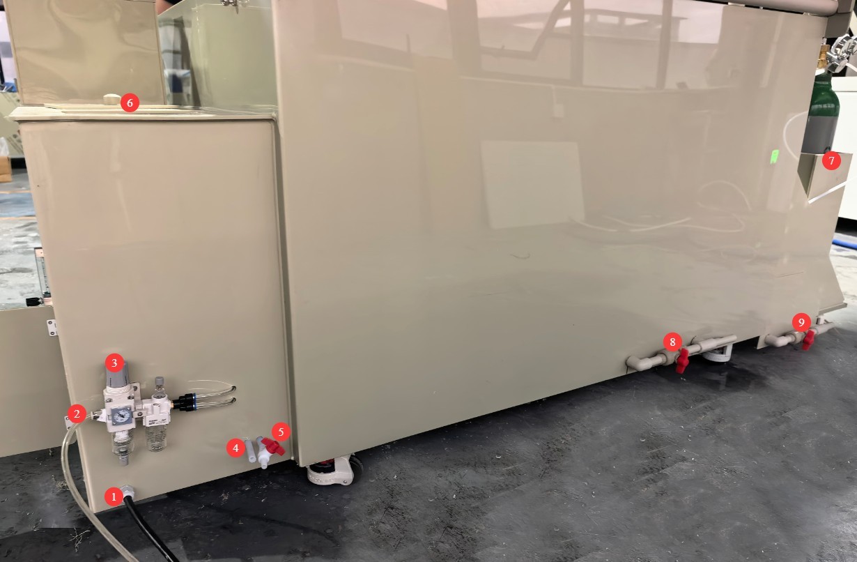
Lihat Gambar 3-2.
| Jumlah | Note |
|---|---|
| ① | Power cord—must be connected to a power source that matches the specifications on the nameplate |
| ② | Air compressor inlet; users must provide their own air compressor. When performing desulfurization, compressed air must be used to remove sulfur dioxide from inside the Sulfur Dioxide Test Machine. |
| ③ | For the air compressor inlet pressure regulating valve, pull it out and adjust the inlet pressure to 0.3 MPa. |
| ④ | Overflow outlet: Water may overflow while the test chamber is running; extend the hose to the drain. |
| ⑤ | Pure Water Tank Drain Valve: This valve should remain closed during normal operation of the test chamber; it should only be opened when it is necessary to drain the water from the pure water tank. A hose can be extended to the drain. |
| ⑥ | Pure water tank, used to automatically replenish the water in the heating water tank inside the test chamber; it is necessary to ensure that the pure water tank remains filled with water throughout the test. |
| ⑦ | Storage Area for Sulfur Dioxide Cylinders |
| ⑧ | Drain valve for the heated water tank inside the test chamber. This valve should remain closed during normal operation of the test chamber; it should only be opened when it is necessary to drain the water from the heated water tank. A hose may be used to extend the drain outlet to a drain. |
| ⑨ | Desulfurization Tower Drain Outlet: This valve should remain closed during normal operation of the test chamber; it should only be opened when it is necessary to drain water from the desulfurization tower. A hose may be used to extend the drain outlet to a designated waste container. |
3.3. Left Side of the Test Chamber
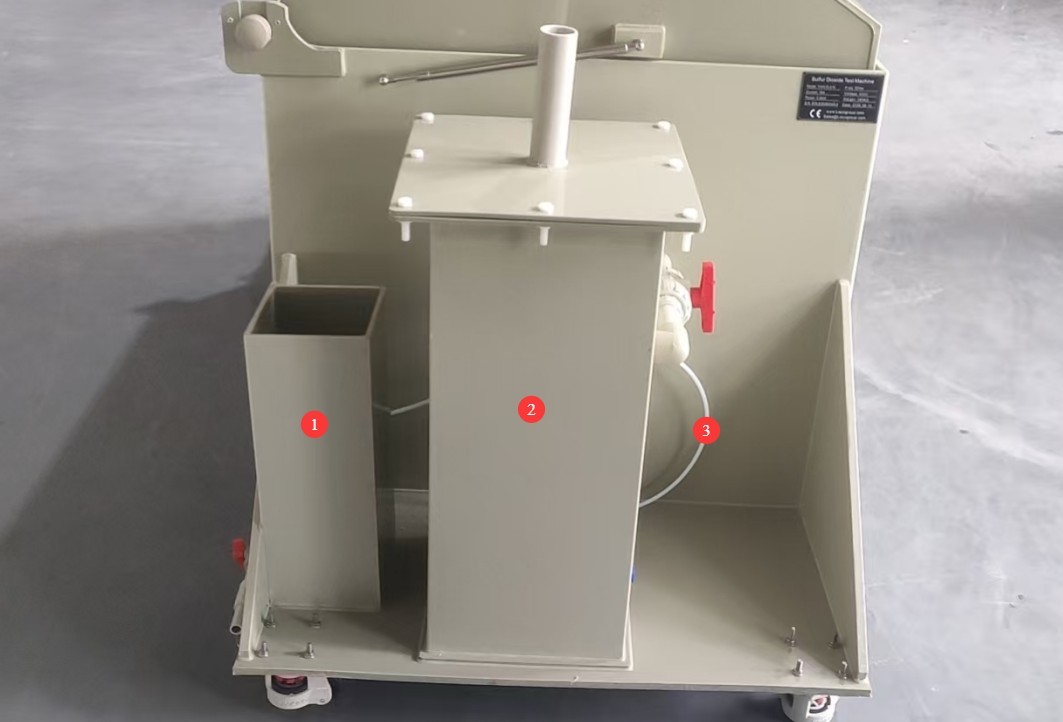
Lihat Gambar 3-3.
| Jumlah | Note |
|---|---|
| ① | Storage Area for Sulfur Dioxide Cylinders |
| ② | Menara Desulfurisasi |
| ③ | The sulfur dioxide inlet tube is a PTFE tube with an inner diameter of 5 mm and an outer diameter of 7 mm, used to connect to the sulfur dioxide cylinder. |
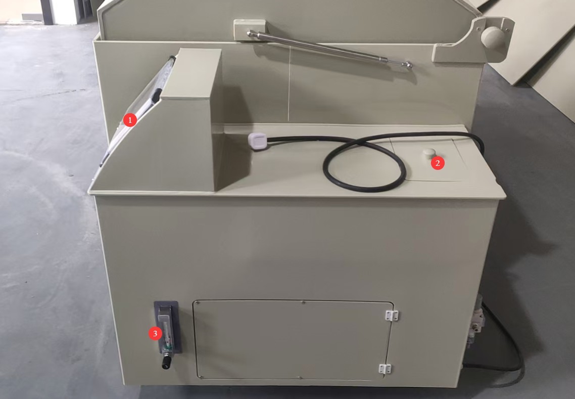
3.4. Right Side of the Test Chamber
Lihat Gambar 3–4.
| Jumlah | Note |
|---|---|
| ① | Touchscreen |
| ② | Tangki Air Murni |
| ③ | Sulfur Dioxide Gas Flow Meter, measured in mL/min |
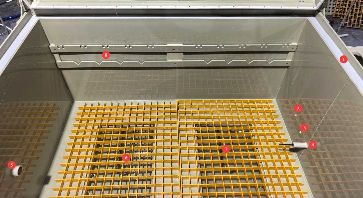
3.5. Inside the Test Chamber
Lihat Gambar 3–5.
| Jumlah | Note |
|---|---|
| ① | Test Chamber Lid Groove |
| ② | Sulfur Dioxide Inlet |
| ③ | Saluran Masuk Udara Terkompresi |
| ④ | Probe Suhu |
| ⑤ | Desulfurization Outlet |
| ⑥⑦ | Tray: During testing, samples can be placed directly on the tray. A heating water bath is located beneath the tray. |
| ⑧ | At the sample holder mounting point, the sample can be suspended from the sample holder during testing. |
4. Pengantar Program Layar Sentuh
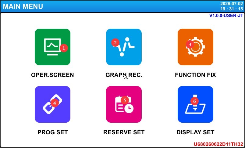
4.1. Antarmuka Utama
Lihat Gambar 4-1.
| Jumlah | Note |
|---|---|
| ① | Antarmuka Pemantauan |
| ② | Temperature curve, used to view temperature curves |
| ③ | Pengaturan Fungsi |
| ④ | Program Settings: For the sulfur dioxide test, only the calibration test is performed; the program settings function will not be covered here. |
| ⑤ | Pengaturan Janji Temu |
| ⑥ | Tampilan Pengaturan |
4.2. Rekaman Pengawasan
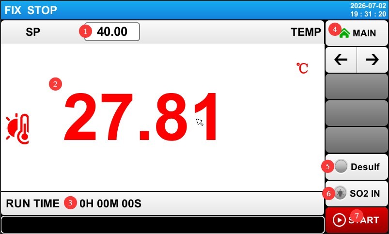
Lihat Gambar 4-2.
| Jumlah | Note |
|---|---|
| ① | Test temperature setting: The standard requirement is 40°C. |
| ② | Real-time temperature display inside the test chamber |
| ③ | Test Duration Display |
| ④ | Return to the Main Screen |
| ⑤ | “Desulfurization” button: After the test is complete, click the “Desulfurization” button to remove the sulfur. |
| ⑥ | Gas Injection Button: Before starting the test, press the Gas Injection Button to ensure that sufficient sulfur dioxide gas enters the test chamber. |
| ⑦ | Start/Stop Test; the test can be started once the intake is complete. |
4.3. Function Settings Interface
Lihat Gambar 4-3.
| Jumlah | Note |
|---|---|
| ① | Test Mode Selection: Please select Fixed Value Mode |
| ② | Restart Procedures Following an Unexpected Power Outage. Stop: An operation that returns the system to a stopped state when power is restored after a power outage during operation; Cold Start: An operation that restarts the system from scratch when power is restored after a power outage during operation; Hot Start: An operation that resumes operation from the point where it was interrupted before the power outage and restores the system to its pre-outage state when power is restored. |
| ③ | Lock settings; once locked, the settings cannot be modified. |
| ④ | Password Setup: If you set a password, you’ll need to enter it the next time you access the settings menu. Entering “0” means no password is required. We recommend not setting a password. |
| ⑤ | Whether to return to room temperature after the test ends: Since the test chamber has no cooling function, this option is not available. |
| ⑥ | The duration of sulfur dioxide injection is calculated based on the test chamber volume (refer to the volume of the test chamber you purchased), the required sulfur dioxide concentration (refer to the applicable standard), and the reading on the sulfur dioxide flow meter (typically 200 mL/min). |
| ⑦ | For the desulfurization duration, use the default setting of 10 minutes. |
| ⑧ | Balik halaman |
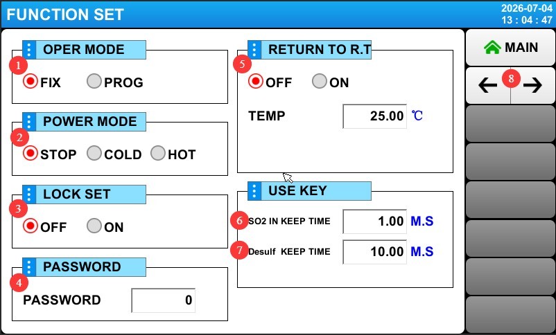
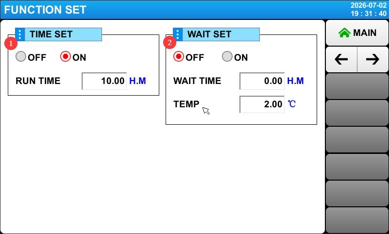
Click to go to the next page and see Figure 4-4.
| Jumlah | Note |
|---|---|
| ① | Test Duration Settings. Select “ON” and set the test duration; the test chamber will automatically stop running once this duration is reached. Select “OFF,” and the test chamber will continue running until you manually click to stop the test. |
| ② | Wait for setup. Select “ON,” set the maximum wait time and temperature difference range, and click “Start Test”; the test duration will begin counting once the temperature inside the test chamber reaches the target value. Select “OFF,” and the test duration will begin counting immediately after clicking “Start Test.” |
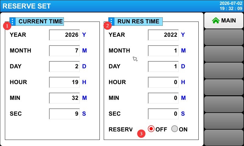
4.4. Appointment Settings Screen
Lihat Gambar 4–5.
| Jumlah | Note |
|---|---|
| ① | The left column shows the current time |
| ② | You can enter your appointment time in the column on the right. |
| ③ | Scheduled Settings. Select “ON” and set the test chamber to standby mode; the test chamber will automatically start the test at the scheduled time. Select “OFF” to cancel the schedule. |
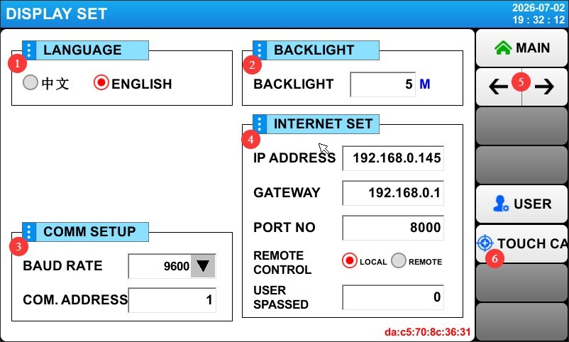
4.5. Display Settings Screen
Lihat Gambar 4–6.
| Jumlah | Note |
|---|---|
| ① | Ganti Bahasa Tampilan |
| ② | Touchscreen Backlight Duration Settings |
| ③④ | The test chamber does not currently have communication capabilities, so no settings need to be configured or modified. |
| ⑤ | Turn the page to view the historical alarm log |
| ⑥ | Touchscreen Calibration: If the touchscreen’s tap location does not match the actual location, follow the instructions to recalibrate the touchscreen. |
5. Operating Procedures for the Sulfur Dioxide Test Machine
5.1. Cleaning the Test Chamber
Before using the test chamber for the first time or after a prolonged period of inactivity, clean the interior of the test chamber and the purified water tank.
5.2. Menambahkan Air
| Water Filling Point | Note |
|---|---|
| Tangki Air Murni | Add purified water; the purified water will automatically flow from the purified water tank into the heating water tank inside the test chamber. To ensure the test duration, fill the purified water tank to capacity. |
| Menara Desulfurisasi | Add purified water until it reaches about two-thirds of the height. |
| Test Chamber Lid Groove | Water may be added to ensure that the test chamber is completely sealed when the lid is closed. |
5.3. Connecting Auxiliary Equipment
| Hubungkan Perangkat | Note |
|---|---|
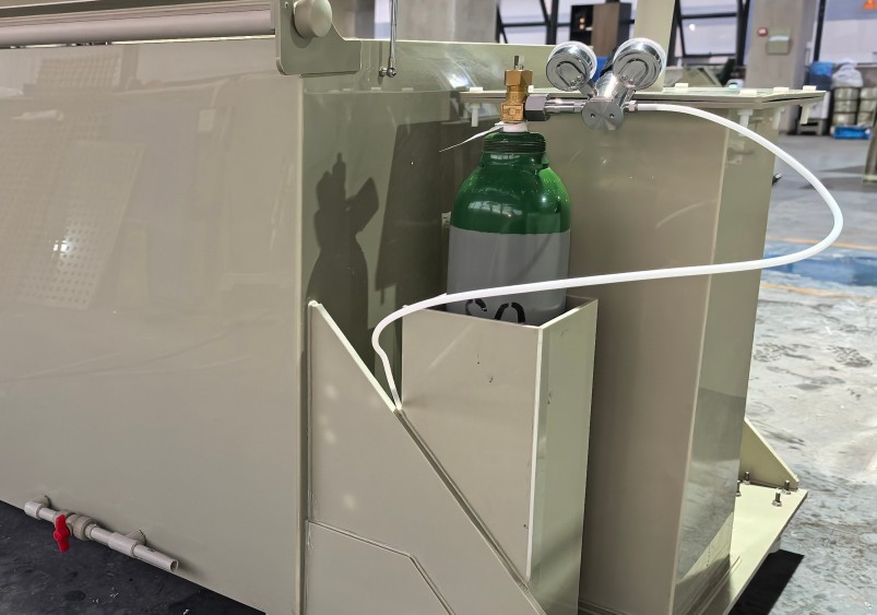
| Sulfur Dioxide Cylinders | See Figure 5-1. Connect the intake pipe. |
| Kompresor udara | Refer to Section 3.2. Connect the intake pipe and adjust the intake pressure to 0.3 MPa. Apply soapy water to all joints and valves, and let them sit for 5 minutes; proceed to the next step only if there are no bubbles and no air leaks. |
5.4. Placing the Sample
Refer to Section 3.5. After placing the sample, close the test chamber lid.
5.5. Sulfur Dioxide Test Procedure
5.5.1. General Operating Procedures
| Tangga | Note |
|---|---|
| ① Test Parameter Settings | Refer to Chapter 4 to configure all test parameters, such as test temperature, fixed test duration, wait function, sulfur dioxide injection duration, and desulfurization duration. |
| ② Sulfur Dioxide Feed Gas | Set the sulfur dioxide air compressor pressure-reducing valve to 0.2 MPa (see Section 4.2), press the “Inlet” button (see Section 3.4), dan adjust the flowmeter to 200 mL/min. Apply soapy water to all fittings and valves to ensure there are no bubbles or air leaks. You may either wait for the gas-injection cycle to end automatically or press the “Gas Injection” button again to stop the gas flow. After stopping the gas flow, close the main valve on the sulfur dioxide cylinder. |
| ③ Start the test | Click START to begin the test. If a wait time has been set, the test duration will begin once the test chamber reaches the target temperature; if no wait time has been set, the test duration will begin immediately after the test is started. |
| ④ Monitoring the Test Process | Ensure that the test chamber temperature can reach the target temperature; ensure that the purified water tank is always filled with water. If the heating water tank runs low on water, the test chamber will sound an alarm and pause the test; once water is added to the purified water tank, the alarm will clear and the test will automatically resume. |
| ⑤ Stop the test | Once the test duration reaches the set time, the test chamber automatically stops the test; users can also click STOP to manually stop the test. |
| ⑥ Desulfurization | Refer to Section 3.1 to open the desulfurization line valve, then refer to Section 4.2 and click the “Desulfurization” button to begin desulfurization. The desulfurization process will automatically stop once the set duration has elapsed; the user may also click the “Desulfurization” button again to stop the process. After desulfurization is complete, close the desulfurization line valve. |
5.5.2. Long-Term Test Procedures
For extended tests lasting several days: It is recommended to vent and refresh the gas once a day, reintroducing fresh sulfur dioxide to maintain a stable concentration. Follow the procedures for desulfurization and sulfur dioxide injection described in Section 5.5.1 when refreshing the gas.
Check the water level in the purified water tank daily and replenish the water lost through evaporation as needed.
5.6. Remove the specimen
After confirming that the desulfurization process is complete, slowly lift the lid slightly to check for any pungent odors.
Put on protective gloves and safety goggles, then fully open the lid of the box.
Use a tool to remove the sample and let it sit in a well-ventilated area.
Do not examine the surface of the specimen up close immediately; wait until the residual gas has dissipated before grading it.
Conduct corrosion rating evaluations or performance tests on the test specimens in accordance with the applicable test standards.
5.7. Prosedur Pasca-Ujian
5.7.1. Cleaning and Returning the Test Chamber to Its Original Position
After the chamber has cooled, rinse the inner walls of the chamber and the test specimen rack with clean water to remove any residual corrosion products; open the drain valve on the heating water tank to drain the wastewater from the bottom of the tank; wipe the chamber lid and the sealing surface around the chamber opening with a dry cloth; turn off the power to the test chamber and the air compressor.
5.7.2. Environmentally Sound Treatment of Waste Liquids
The absorption liquid in the desulfurization tower is acidic and must be replaced after one week of continuous use. Open the desulfurization tower’s drain valve to discharge it into a designated waste liquid container; the waste liquid must be neutralized with an alkaline solution (sodium hydroxide or lime water) to a pH of 6–9 before discharge; it is strictly prohibited to discharge acid-containing wastewater directly into the sewer system.
Safety Guidelines for Neutralization: Wear acid- and alkali-resistant gloves and safety goggles; slowly pour the alkaline solution into the acidic waste liquid while stirring and monitoring the pH to prevent splashes and chemical burns.
6. Daily Maintenance and Care of the Test Chamber
6.1. Routine Inspection Items
The following checks should be performed before and after each test: Check the air line connections for looseness or leaks; check the interior and exterior of the tank for cracks or damage; check that all valves are in the correct position; and confirm that the water levels in the desulfurization tower and the purified water tank are normal.
6.2. Rencana Pemeliharaan Terjadwal
6.2.1 Weekly Maintenance Tasks
Replace the absorption water in the desulfurization tower to maintain absorption efficiency; replace the water in the heating tank of the test chamber to keep the water clean; Clean the water trough on the test chamber lid to prevent scale buildup; check the gas cylinder pressure to ensure sufficient gas supply; if the remaining pressure on the gas cylinder pressure gauge falls below 0.5 MPa, stop the test and replace the sulfur dioxide cylinder with a new one.
6.3. Penyimpanan dan Pemeliharaan Jangka Panjang
When the equipment will not be used for an extended period, drain all standing water from the pipes; thoroughly clean the interior and exterior of the unit, allow it to air dry, and then close the lid; disconnect the power supply and cover the unit with a dust cover; store it in a dry, well-ventilated environment at a temperature between 0°C and 40°C; power on the unit once a month for 30 minutes to remove moisture.
6.4. Calibration Interval Requirements
To ensure the measurement accuracy and operational reliability of the test chamber, it is recommended that it be sent periodically to a qualified third-party metrology organization for calibration. The recommended calibration interval is 12 months. Users may determine the specific calibration interval based on frequency of use, environmental conditions, and quality system requirements.
7. Troubleshooting Common Problems and Solutions
| Gejala Kesalahan | Kemungkinan penyebab | Prosedur |
|---|---|---|
| When sulfur dioxide is introduced, the flow meter shows no reading when adjusted. | The sulfur dioxide cylinder is underpressurized, and the pressure-reducing valve is not open. | See Section 6.2.1 to check the cylinder pressure; see Section 5.5.1 to check the cylinder pressure regulator. |
| The touchscreen displays a low-water warning | Low Water Level in the Heating Tank | Refill the purified water tank with purified water |
| The temperature does not rise or rises slowly | Heating Element Failure | Mengganti Elemen Pemanas |
| Temperature Out of Control—Overheating | Solid-State Relay Breakdown | Replacing a Solid-State Relay |
| There has been a sulfur dioxide gas leak, and a pungent gas is escaping. | Air leaks at fittings, valves, and test chamber lids | Use soapy water to check for air leaks at the joints and valves; ensure the test chamber lid remains airtight; water may be added to the lid groove to seal it. |