
 Inggris
 中文简体
中文简体 Русский
 Español
 Português
 Türkçe
 العربية
 Deutsch
 Polski
 Italiano
 Français
 한국어
한국어 ไทย
ไทย Tiếng Việt
 日本語
日本語





























Generator Surge
Pengguna manual
berlaku LISUN Model: SG61000-5,SG61000-5SB
1. Membuka Kemasan dan Mengenal Peralatan Secara Dasar
1.1 Spesifikasi Teknis Utama
| LISUN Pilih Model | SG61000-5SB | SG61000-5 |
| Bentuk Gelombang Tegangan Nyala | 1.2/50 μs ± 20% | |
| Bentuk Gelombang Arus Hubung Singkat | 8/20 μs ± 20% | |
| Output Impedance | 2Ω dan 12Ω | |
| Rentang Tegangan Output | 0–4.8 kV ±5% | 0–6 kV ±5% |
| Output Kisaran Arus | 0–2.4 kA ±5% | 0–3 kA ±5% |
| Jumlah lonjakan | 1 – 9999 kali | |
| Polaritas | Terminal Positif, Terminal Negatif, dan Otomatis Sepenuhnya | |
| Tahap | Asinkron, Sinkron: Pengujian sudut 0°–360° atau sudut yang ditentukan | |
| Fitur Khusus | N / A | Brand-new free upgrade: Includes built-in Voltage Probe and current attenuator probes, as well as an electronic oscilloscope, allowing you to view output waveforms directly on the touchscreen! |
| Prosedur operasi | Input layar sentuh LCD, sistem operasi Android bawaan. | |
| Dimensi (W x D x H) | 44 × 45 × 35 cm | |
| Berat Kotor | Tentang 30 kg | |
| Jaringan Kopling dan Dekopling (CDN Terintegrasi) | AC 240 V/16 A Fase Tunggal CDN | |
| Transformator Isolasi EUT (Eksternal, Opsional) | LISUN ITEU-SP4K (220V satu fasa) atau ITUS-SP2K (110V) | |
1.2 Membuka Kemasan dan Memeriksa Isinya
1.2.1 Membuka Kemasan dan Pemeriksaan Visual
Saat membuka kemasan perangkat, tangani dengan hati-hati untuk menghindari goresan pada casing dengan alat tajam. Setelah membuka kemasan, periksa terlebih dahulu bagian luar perangkat untuk memastikan tidak ada deformasi atau penyok yang terlihat, dan tombol-tombolnya tidak rusak atau longgar.
Jika Anda melihat adanya kerusakan atau perubahan bentuk pada peralatan atau aksesori, jangan nyalakan daya. Segera hubungi kami.
1.2.2 Host dan Aksesoris
Host-type, see Figure 1-1.
| Jumlah | Note |
| ① | SG61000-5 Generator Surge |
| ② | ITEU Series Isolation Transformers, used to power samples via lightning surges |
| ③ | PD-E01, EUT sample box, designed to prevent splashes from the EUT during testing; when opened, the PD-E01 sample box automatically disconnects the EUT cables to prevent accidental electric shock |
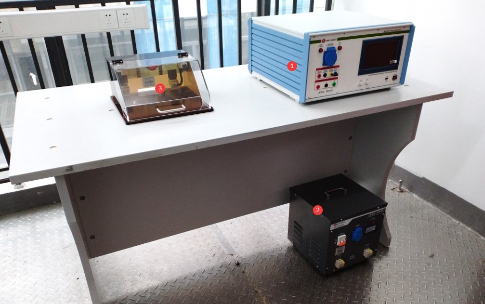
Gambar-1 1
Catatan 1: Generator lonjakan arus harus digunakan bersamaan dengan transformator isolasi untuk melindungi jaringan listrik; manual ini menggunakan seri transformator isolasi ITEU sebagai contoh.
Note 2: The PD-E01 sample box is optional. During testing, samples may be severely damaged by surges or even cause parts to fly off; place the sample in the sample box to ensure a safe testing environment. The dimensions of the sample box can be customized to fit the size of the EUT sample.
Standard accessories, as shown in Figures 1–2: ① Isolation Transformer output cable, connecting the Isolation Transformer’s output terminal to the CDN input terminal of the Surge Generator; ② Isolation Transformer power cord; ③ Surge Generator power cord; ④ EUT test lead, connecting the Surge Generator to the test specimen;⑤ Banana plug cable, for backup; ⑥ Ground wire, used to connect to the PGND protective ground terminal; ⑦ Coaxial cable, used to connect to an external oscilloscope for monitoring surge waveforms; ⑧ Discharge tube, used to check whether the equipment is outputting surges in the event of a malfunction.
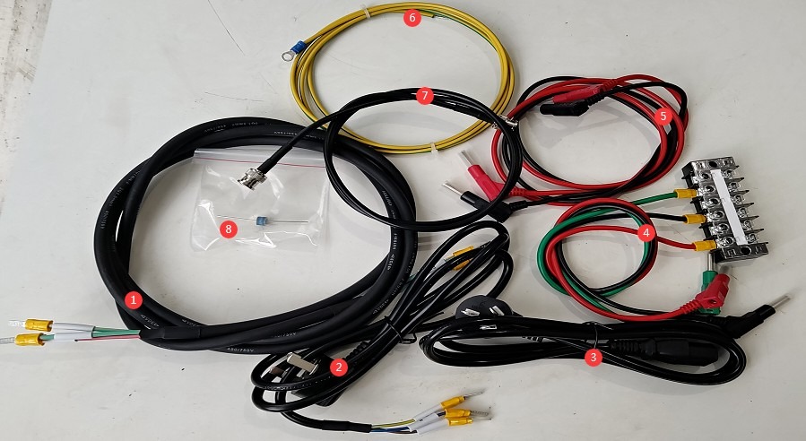
Gambar 1–2
1.3 Mengunduh Dokumen Elektronik
Kami telah mengirimkan tautan unduhan untuk manual pengguna elektronik, sertifikat kalibrasi, kartu garansi, dan dokumen lainnya melalui email pada saat pengiriman. Silakan unduh sesegera mungkin. Jika Anda belum menerima email tersebut, silakan hubungi kami untuk meminta tautan unduhan lagi.
2. Tindakan Pencegahan Keamanan
2.1 Pedoman Penempatan
Ensure the ambient temperature is between 15°C and 35°C, relative humidity is between 10% and 60% (no condensation), and atmospheric pressure is between 86 kPa and 106 kPa to prevent damage caused by high-voltage short circuits or moisture ingress;
Tempat tersebut harus bebas dari interferensi elektromagnetik yang kuat, gas korosif, bahan yang mudah terbakar atau meledak, dan debu, serta harus berventilasi baik untuk mencegah percikan listrik menimbulkan bahaya;
Place it on a stable workbench; avoid tilting or inverting it, and keep it away from sources of vibration;
Transformator Isolasi: Jauhkan setidaknya 0.5 meter dari unit utama untuk mencegah interferensi kopling elektromagnetik;
The equipment must be placed at least 1000 mm away from walls and surrounding structures (such as other testing equipment and shelving) to facilitate maintenance; at least 2000 mm of space must be left in front of the equipment to ensure smooth operation, and there must be no obstructions in the surrounding area.
2.2 Standar Keselamatan Tegangan Tinggi
2.2.1 Pemeriksaan Keamanan
Verify that the equipment’s power supply voltage matches the mains voltage: AC 220 V ±10% (AC 110 V available upon request), 50/60 Hz. Ensure that the power supply is properly grounded and that the grounding wire is free of damage or looseness;
Persyaratan Pembumian: Terminal pembumian pelindung (PGND) unit utama harus dihubungkan ke tanah, dengan resistansi pembumian ≤1 Ω, untuk memastikan pelepasan tegangan tinggi yang aman;
Operator harus memiliki tangan yang kering dan tidak boleh mengenakan perhiasan logam apa pun.
2.2.2 Persyaratan Keselamatan untuk Prosedur Operasional
Operators must undergo professional training and be familiar with this manual and the relevant standards. Non-professionals are prohibited from operating or disassembling the equipment. The equipment contains high-voltage circuits; opening the cover may pose an electric shock hazard. Contact the manufacturer’s technical staff for repairs.
Peralatan ini menghasilkan tegangan tinggi (hingga 6 kV) dan lonjakan arus tinggi selama pengoperasian. Jangan sentuh konektor keluaran pulsa, terminal EUT, atau port CDN dalam keadaan apa pun.
During testing, unauthorized personnel must not remain within 1 meter of the EUT to prevent accidental electric shock or interference from electrical discharges.
Sebelum mengganti sambungan atau mengganti EUT, Anda harus terlebih dahulu memastikan bahwa output tegangan tinggi dimatikan (lampu indikator HV mati) dan menunggu setidaknya 5 menit untuk memastikan bahwa kapasitor tegangan tinggi internal telah sepenuhnya habis dayanya.
Jangan makan atau minum selama pengujian untuk mencegah kecelakaan akibat sengatan listrik.
Jika melibatkan beberapa orang, tetapkan peran dan tanggung jawab dengan jelas, dan konfirmasikan satu sama lain sebelum memulai pengujian untuk menghindari kesalahan.
2.3 Langkah-langkah Tanggap Darurat
Jika terjadi sengatan listrik: Segera matikan aliran listrik utama ke peralatan, pindahkan operator ke area yang aman, berikan pertolongan pertama jika perlu, dan hubungi petugas medis.
Kerusakan Peralatan (Asap, Suara Aneh, Bau Aneh): Segera matikan peralatan dan cabut catu daya; cabut semua kabel; jangan hidupkan kembali peralatan; hubungi produsen untuk perbaikan.
Keluaran lonjakan abnormal: Hentikan pengujian, hubungi produsen untuk pemecahan masalah, dan jangan sentuh port pengujian secara langsung dengan tangan Anda.
2.4 Lainnya
Untuk hal-hal yang tidak tercakup dalam panduan ini, harap berhati-hati atau hubungi kami.
3. Persiapan Sebelum Ujian
3.1 Urutan Pengkabelan Perangkat Keras
Connect ground terminal ① on the back of the host to ground, as shown in Figure 3-1.
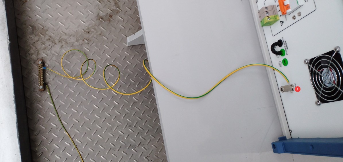
Gambar-3 1
The two ports labeled ① and ② on the front of the main unit are both built-in CDN output ports that can be connected to the EUT (Equipment Under Test). Select one based on the EUT’s current and wiring configuration; see Figure 3-2.
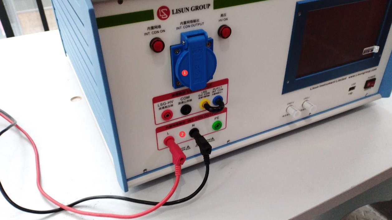
Gambar-3 2
For safety reasons, the EUT may be placed in the sample box, as shown in Figure 3-3.
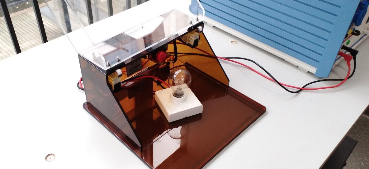
Gambar-3 3
Note 1: Before testing, verify that the EUT is in normal operating condition and meets the product’s rated operating conditions.
Note 2: The EUT should preferably be placed on the left side of the equipment so that the EUT connection cables do not need to pass in front of the surge generator’s touchscreen, thereby preventing interference with the touchscreen during the test.
For the Isolation Transformer wiring, see Figures 3-4 and 3-5. Depending on the EUT’s rated current and wiring configuration, connect one of the output ports (① or ②) to the built-in CDN input port (④) on the back of the host unit. Port ③ is the input port; connect the Isolation Transformer’s power cord to it.
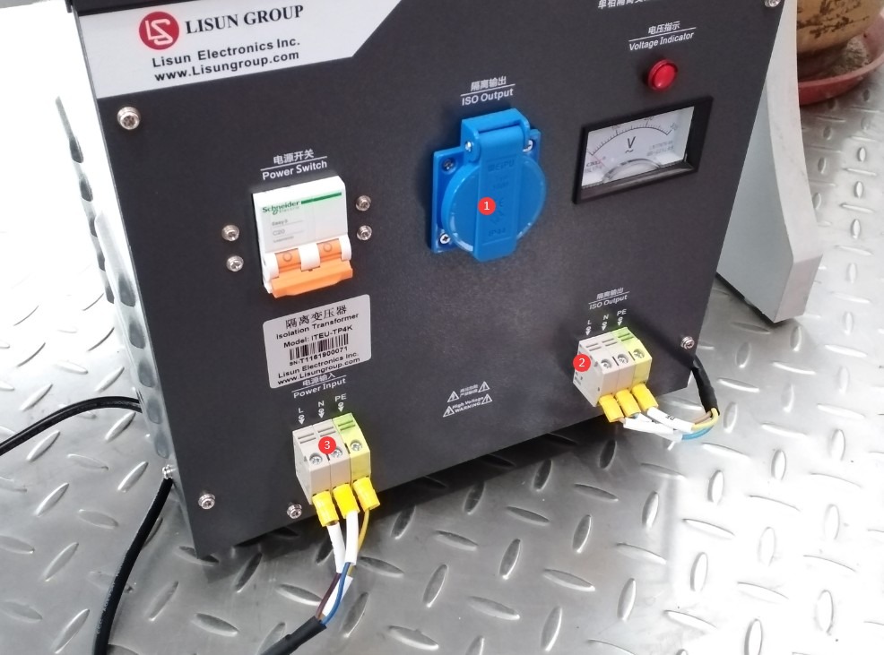
Gambar-3 4
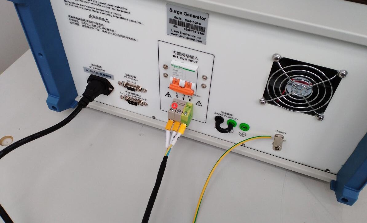
Gambar-3 5
Next, connect the power cords of the Surge Generator and the Isolation Transformer to an appropriate power source.
Note: The Isolation Transformer is used only to supply power to the EUT via the host’s built-in CDN; the Surge Generator’s own power supply does not need to be connected to the Isolation Transformer.
3.2 Konfirmasi Parameter Uji
3.2.1 Pemilihan Tingkat Tes
Based on the EUT installation environment and product standards, select the corresponding test level (priority levels are listed in the table below); lower levels must meet compatibility requirements:
| Tingkat Tes | Tegangan Uji Kerusakan (±10%) | Skenario yang Berlaku |
| Level 1 | 0.5 kV | Lingkungan dalam ruangan yang terawat dengan baik. |
| Level 2 | 1.0 kV | Lingkungan Dalam Ruangan yang Khas |
| Level 3 | 2.0 kV | Lingkungan luar ruangan atau semi-luar ruangan |
| Level 4 | 4.0 kV | Lingkungan luar ruangan yang keras |
| Kelas X | Tegangan Spesifik | Skenario khusus yang ditentukan dalam standar produk. |
3.3 Pemanasan Peralatan dan Uji Mandiri
Nyalakan sakelar daya di panel depan perangkat utama; perangkat akan masuk ke mode siaga, lampu indikator daya menyala, dan kipas pendingin mulai beroperasi.
Wait 5 minutes for the device to warm up, and check that the touchscreen is displaying normally and shows no error messages.
4. Pengantar Program Layar Sentuh
The program’s initial screen, as shown in Figure 4-1.
| Jumlah | Note |
| ① | Settings Interface for the Built-in Digital Oscilloscope |
| ② | Pedoman Penggunaan Umum (Fitur ini masih dalam pengembangan; mohon jangan mengaksesnya atau melakukan tindakan apa pun saat ini) |
| ③ | Layar Informasi Sistem |
| ④ | Beralih antara Bahasa Mandarin dan Bahasa Inggris |
| ⑤ | Antarmuka Program |
| ⑥ | Surge Test Interface |
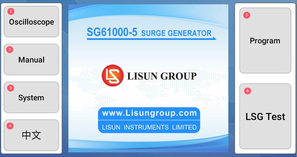
Gambar-4 1
Catatan: SG61000-5SB does not have an oscilloscope function, while the SG61000-5 tidak.
4.1 Antarmuka Pengaturan Fungsi Osiloskop
See Figure 4-2. Simply check all the boxes, and the current surge waveform will be displayed automatically after each surge test is completed.
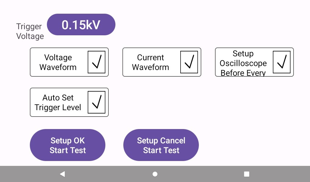
Gambar-4 2
4.2 Antarmuka Program
Used to create new programs or manage existing ones; see Figure 4-3.
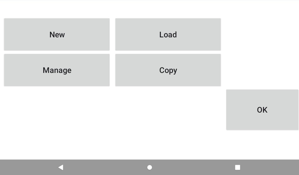
Gambar-4 3
If you need to test the program, simply enter all the parameters to be tested step by step as needed and then save them, as shown in Figure 4-4.
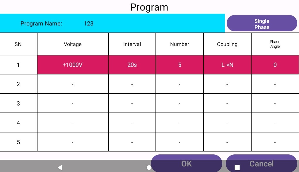
Gambar-4 4
4.3 Antarmuka Uji Lonjakan
Lihat Gambar 4–5.
| Jumlah | Note |
| ① | Surge Voltage and Polarity Settings |
| ② | Surge Interval Setting |
| ③ | Surge Count Setting |
| ④ | Surge Coupling Direction Settings |
| ⑤ | Surge Phase Angle Setting |
| ⑥ | Common-Mode Impedance Selection (Default: 12 Ω; optional: 2 Ω; no setting required for differential mode—fixed at 2 Ω) |
| ⑦ | EUT Parameter Monitoring Settings |
| ⑧ | You can run the edited program directly to test it. |
| ⑨ | EUT Voltage and Current Display |
| ⑩ | Click to turn on (or off) the EUT’s power |
| ⑪ | Click to start or stop the surge test |
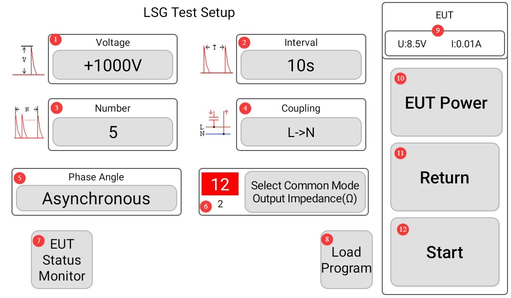
Gambar 4–5
Catatan: Untuk menampilkan bentuk gelombang lonjakan saat ini secara otomatis di layar, atur interval lonjakan minimal 10 detik; jika tidak, program tidak akan memiliki cukup waktu untuk menampilkan bentuk gelombang lonjakan.
4.3.1 Antarmuka Pengaturan Arah Kopling Lonjakan
You can select a single coupling direction, or click “Auto” to select multiple coupling directions simultaneously; see Figures 4–6.
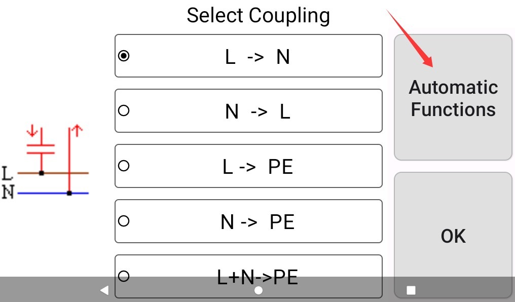
Gambar 4–6
On the “Automatic Functions” screen, you can select various combinations of coupling directions, or click “General” to return to selecting a single coupling direction, as shown in Figure 4-7.
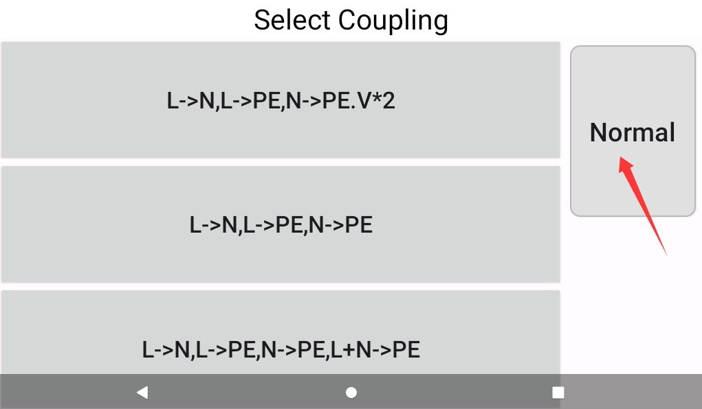
Gambar 4-7
4.3.2 Antarmuka Pengaturan Sudut Gelombang
You can select asynchronous, a single surge angle, or click “Auto” to select multiple coupling angles simultaneously, as shown in Figure 4-8.
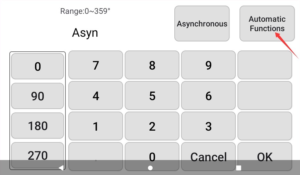
Gambar-4 8
In the “Auto Function” interface, you can select from a variety of angle combinations. Click the button marked in the image below to return; see Figure 4-9.
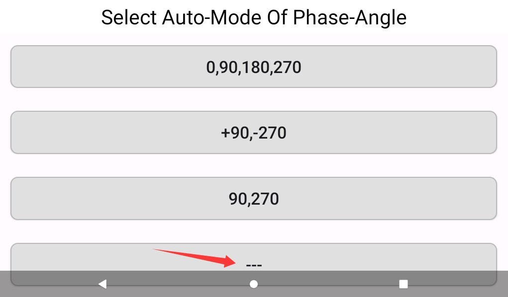
Gambar-4 9
4.3.3 Antarmuka Pengaturan Pemantauan Parameter EUT
Lihat Gambar 4-10.
| Jumlah | Note |
| ① | √ indicates that EUT parameters are monitored; × indicates that EUT parameters are not monitored |
| ② | √ Indicates that surge peak data is monitored; × indicates that surge peak data is not monitored. |
| ③ | √ The device automatically stops the surge test when the EUT’s voltage and current data exceed the set limits. |
| ④ | √ When the peak surge voltage or current exceeds the set limits, the device automatically stops the surge test. |
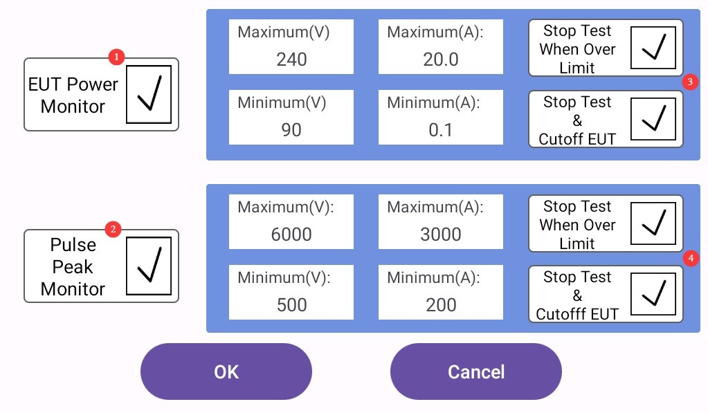
Gambar-4 10
Catatan 1: Pengguna dapat memilih untuk memantau parameter EUT dan data puncak lonjakan selama pengujian atau tidak; hal ini tidak memengaruhi pengujian lonjakan.
Note 2: If you select option ③ or ④, the surge test may be unexpectedly interrupted due to the triggering of a protection mechanism. Please choose carefully and set appropriate limits.
5. Pengujian Lonjakan
5.1 Prosedur Operasional
After all the parameters in the touchscreen program have been set, turn on the Isolation Transformer. Turn on the air circuit breaker for the built-in network CDN on the back of the main unit, as shown in Figure 5-1.
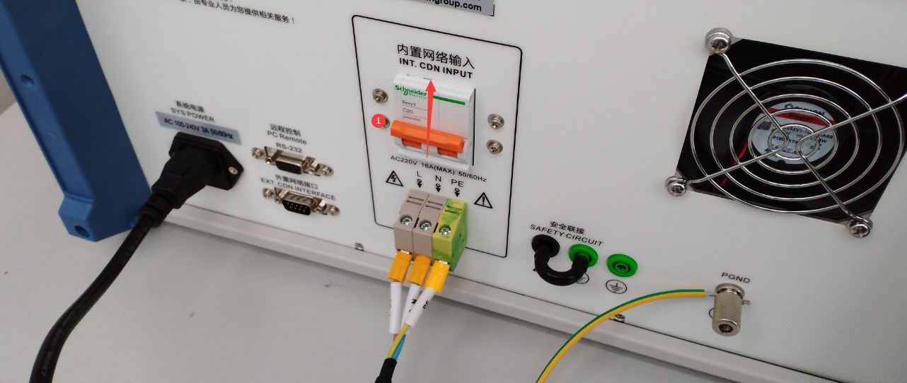
Gambar-5 1
Start the test; see Figure 5-2.
| Tangga | Note |
| ① | Click “EUT Power” to power on the EUT |
| ② | Then click “Start” to begin the test. |
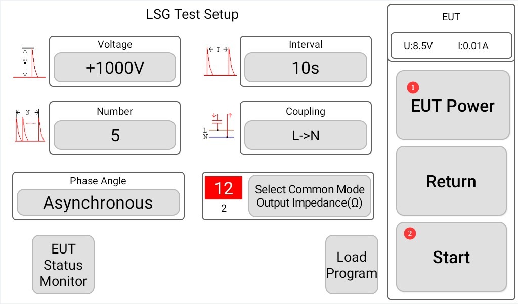
Gambar-5 2
If the oscilloscope function is checked, the program interface will display the surge voltage and current waveforms after each surge output, as shown in Figure 5-3:
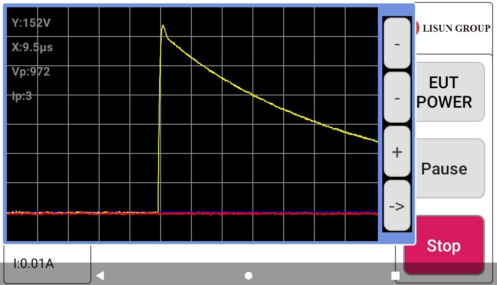
Gambar-5 3
Note: When the EUT is connected and testing is proceeding normally, the surge voltage and current values and waveforms will be affected. The surge voltage and voltage waveform (1.2/50 μs) specified in the standard must be measured under a fully open-circuit condition; the surge current and current waveform (8/20 μs) specified in the standard must be measured under a fully short-circuit condition.
Open circuit, meaning that no EUT or cable is connected to the CDN output terminal, as shown in Figure 5-4:
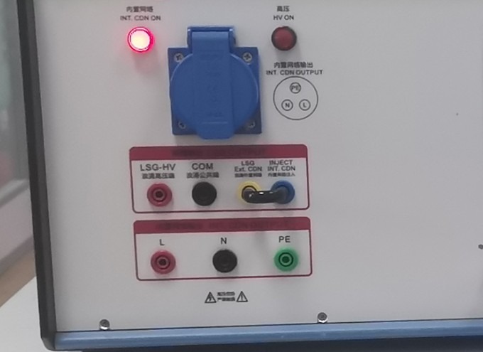
Gambar-5 4
For a complete short circuit, the two ends of the surge coupling direction must be short-circuited. For example, if the current coupling direction is set to L> N, the L and N terminals at the CDN output must be short-circuited, as shown in Figure 5-5;
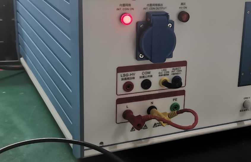
Gambar-5 5
5.2 Menentukan Apakah EUT Telah Lulus Uji
| Tingkat | Kriteria evaluasi | Lulus atau Gagal | Gejala Khas |
| Nilai A (Kriteria A) | Performa sepenuhnya normal dalam batas yang ditentukan, tanpa anomali apa pun. | Biasanya dianggap telah lulus | No downtime, resets, display errors, or data loss; key parameters are within acceptable limits. |
| Nilai B (Kriteria B) | Temporary loss or reduction in function or performance, but recovery occurs automatically once the disturbance ceases, without the need for operator intervention | Harus diatur terlebih dahulu; umumnya dapat diterima. | Secara otomatis melanjutkan pemutaran setelah gangguan komunikasi singkat; kembali normal setelah layar berkedip; kembali normal setelah penyimpangan singkat dari parameter. |
| Kelas C (Kriteria C) | Temporary loss or reduction in functionality or performance that requires manual intervention to restore (e.g., restart, reset) | Harus diatur terlebih dahulu; dapat diterima dalam situasi tertentu. | Jika peralatan macet, peralatan tersebut harus dihidupkan ulang secara manual; jika program mengalami kerusakan, program tersebut harus dimuat ulang; jika parameter berada di luar rentang yang ditentukan, parameter tersebut harus disesuaikan secara manual. |
| Nilai D (Kriteria D) | Hilangnya fungsi secara permanen atau penurunan kinerja akibat kerusakan perangkat keras/perangkat lunak atau kehilangan data. | Ditetapkan sebagai kegagalan | Komponen terbakar, papan sirkuit rusak, data yang tersimpan hilang secara permanen, fungsi inti tidak dapat dipulihkan. |
5.3 Post-Test Procedures
5.3.1 Pemutusan Peralatan
Jika EUT terlihat rusak selama pengujian, segera ketuk “Hentikan Pengujian” pada layar sentuh dan ketuk “Daya EUT” untuk mematikan daya EUT.
If no abnormalities occur during the test, wait for the surge test to end automatically, then click “EUT Power” to turn off the EUT’s power.
Turn off the circuit breaker for the host’s built-in network CDN.
Wait 5 minutes to ensure that the high-voltage capacitors inside the main unit have fully discharged, then replace the EUT for testing, or turn off the power to the main unit and the Isolation Transformer.
5.3.2 Tidying Up and Cleaning
Bersihkan area pengujian dan lap dengan kain kering. Jangan gunakan alkohol atau bahan pembersih korosif.
Surge testing is a destructive test; it does not automatically generate a test report, but the device automatically saves the test data. You can go to “System Information,” click “Test Log,” and export the corresponding test data to a USB flash drive via the USB port. The exported file is in TXT text format, as shown in Figures 5-6.
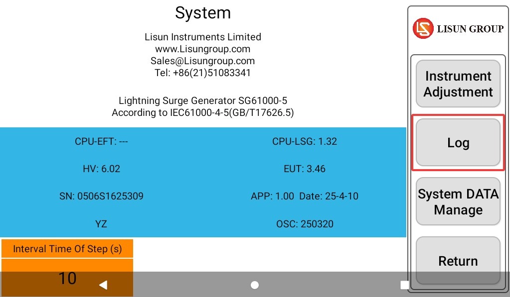
Gambar 5–6
6. Perawatan dan Pemeliharaan Rutin
6.1 Penyimpanan Peralatan
6.1.1 Persyaratan Penyimpanan Jangka Pendek
Jika peralatan tersebut digunakan setiap hari, tidak diperlukan tindakan lebih lanjut setelah setiap pengujian selesai dan peralatan telah dibersihkan.
6.1.2 Persyaratan Penyimpanan Jangka Panjang
Jika perangkat tidak akan digunakan dalam jangka waktu lama (lebih dari satu bulan), harap lepaskan semua kabel dan tutupi perangkat dengan penutup debu untuk mencegah penumpukan debu.
The device should be powered on once a month and left on for half an hour to prevent the aging of electrical components (such as capacitors and contactors).
6.2 Persyaratan Interval Kalibrasi
To ensure the instrument’s measurement accuracy and operational reliability, it is recommended that it be sent periodically to a qualified third-party metrology laboratory for calibration. The recommended calibration interval is 12 months. Users may determine the specific calibration interval based on frequency of use, environmental conditions, and quality system requirements.
7. Gunakan perangkat eksternal untuk memverifikasi keluaran lonjakan arus.
7.1 Using an External Oscilloscope (Using the LISUN Osiloskop Seri OSP sebagai Contoh)
7.1.1 Menggunakan Port CRO
7.1.1.1 Melihat Bentuk Gelombang Tegangan Lonjakan
Set the following parameters for the Surge Generator: Set the surge voltage to +1 kV, set the coupling direction to L to N, set the interval as short as possible (e.g., 5 seconds), and set the number of surges to a higher value to make it easier to view each waveform.
Do not connect any EUT; ensure that the circuit is completely open. Then, use the coaxial cable provided to connect the lightning surge tester’s ① “CRO-V” port to the ② oscilloscope, as shown in Figure 7-1.
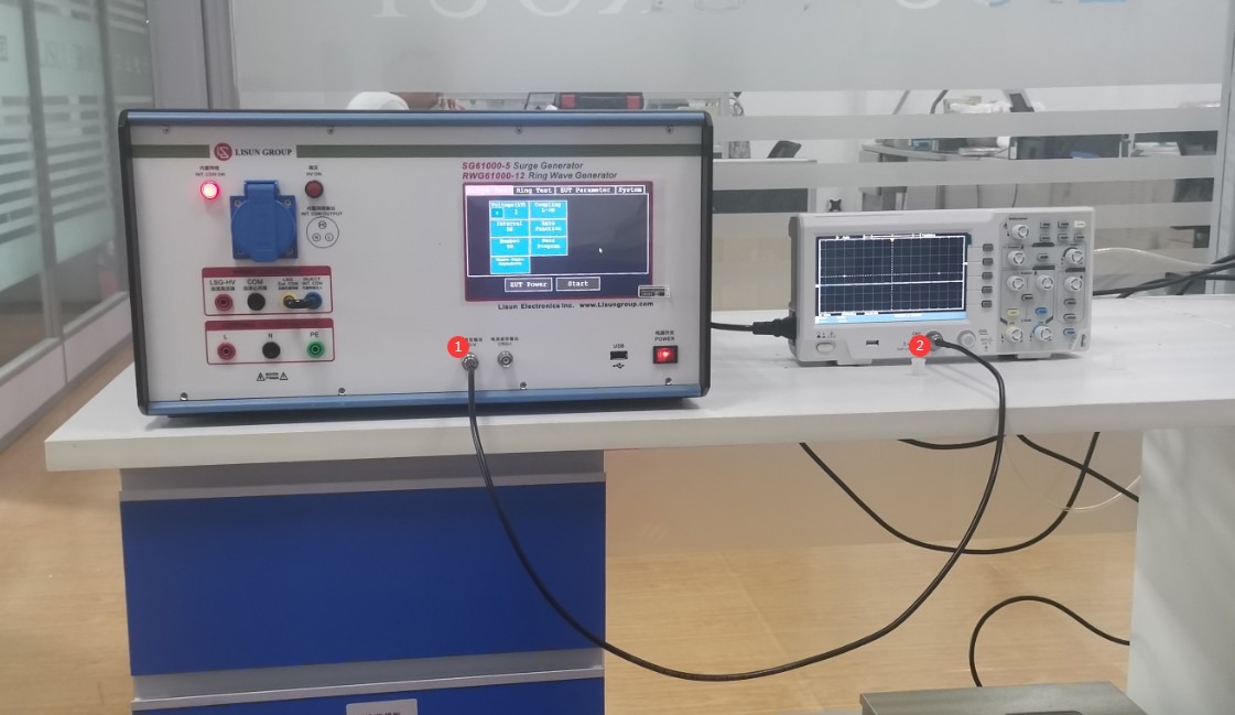
Gambar-7 1
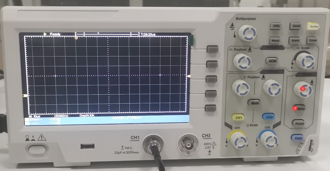
Press the ① “Menu” button below the ② “Trigger” button, as shown in Figure 7-2.
Gambar-7 2
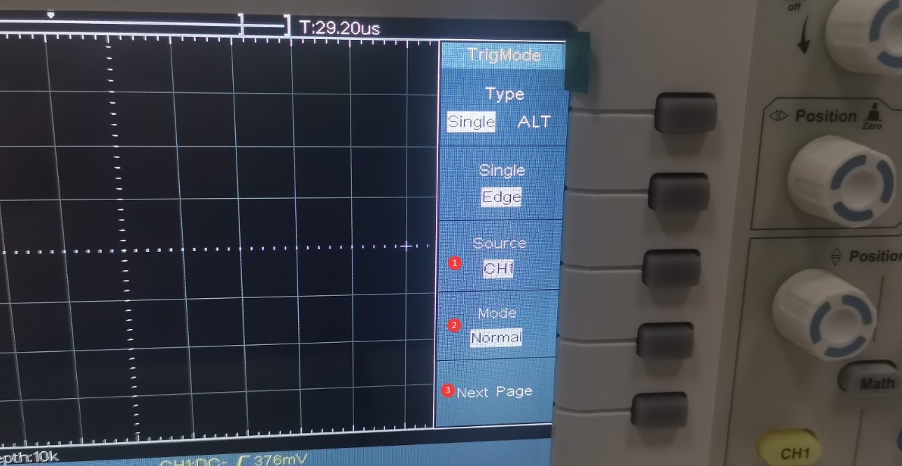
See Figure 7-3: ① Select the connected channel; ② Set the trigger mode to “Normal”; ③ Click to proceed to the next page.
Gambar-7 3
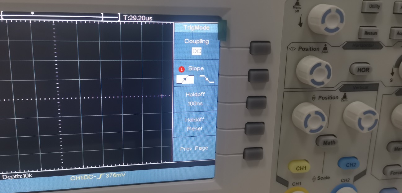
See Figure 7-4; ① Select the rising edge.
Gambar-7 4
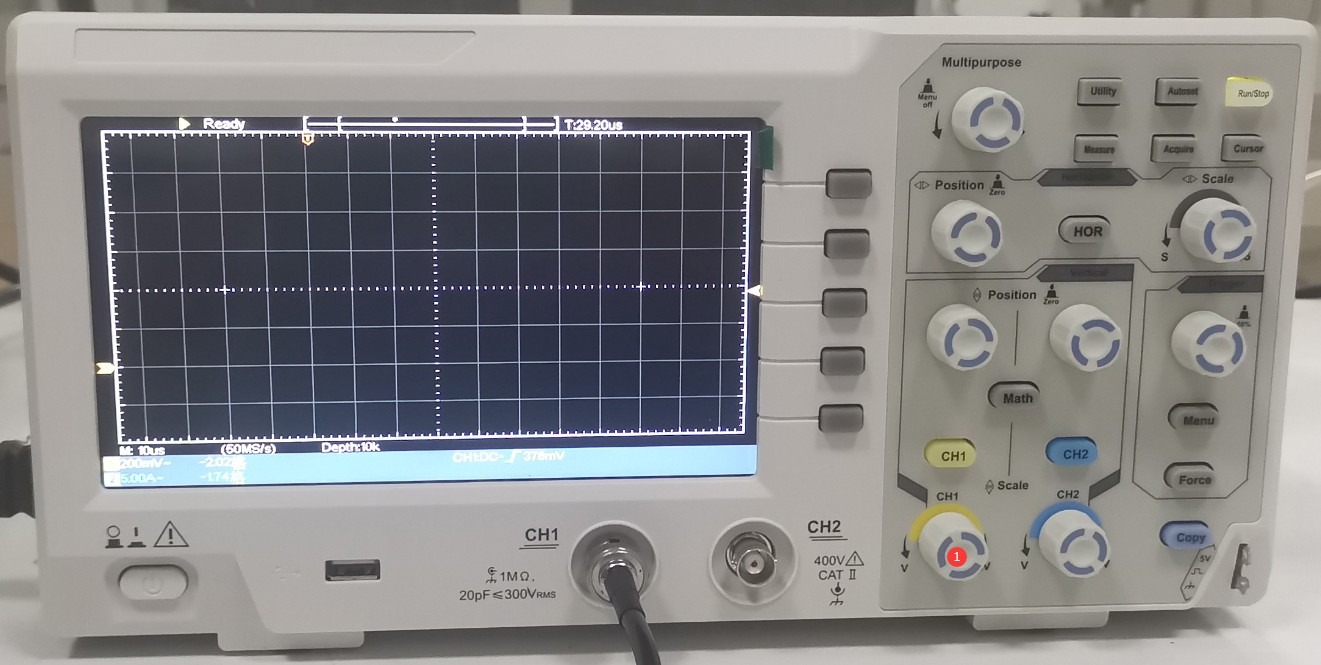
As shown in Figure 7-5, press the ① CH1 knob.
Gambar-7 5
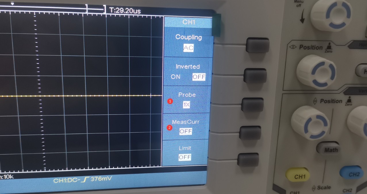
See Figure 7-6: ① Select the 1X range; ② Turn off the current test function.
Gambar-7 6
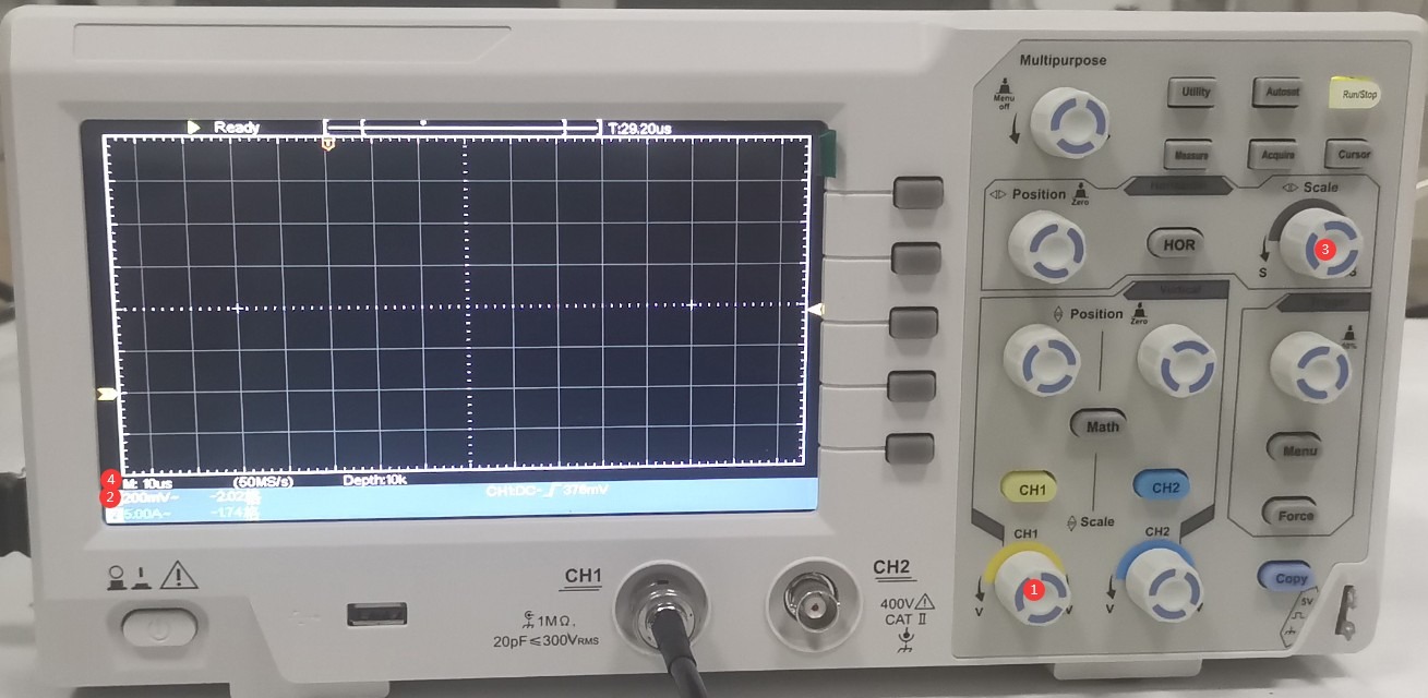
The SG61000-5 series surge generator has a built-in 1000:1 Voltage Probe at the CRO interface. If the surge voltage is set to +1 kV, the actual voltage applied to the oscilloscope is 1 V. Refer to Figure 7-7. Turn the ① CH1 knob to set the ② oscilloscope’s vertical scale to 1/5 per division, or 200 mV, which makes it easier to view the entire waveform. Turn the ③ “Scale” knob to set the ④ oscilloscope’s horizontal time scale to 10 µs per division.
Gambar-7 7
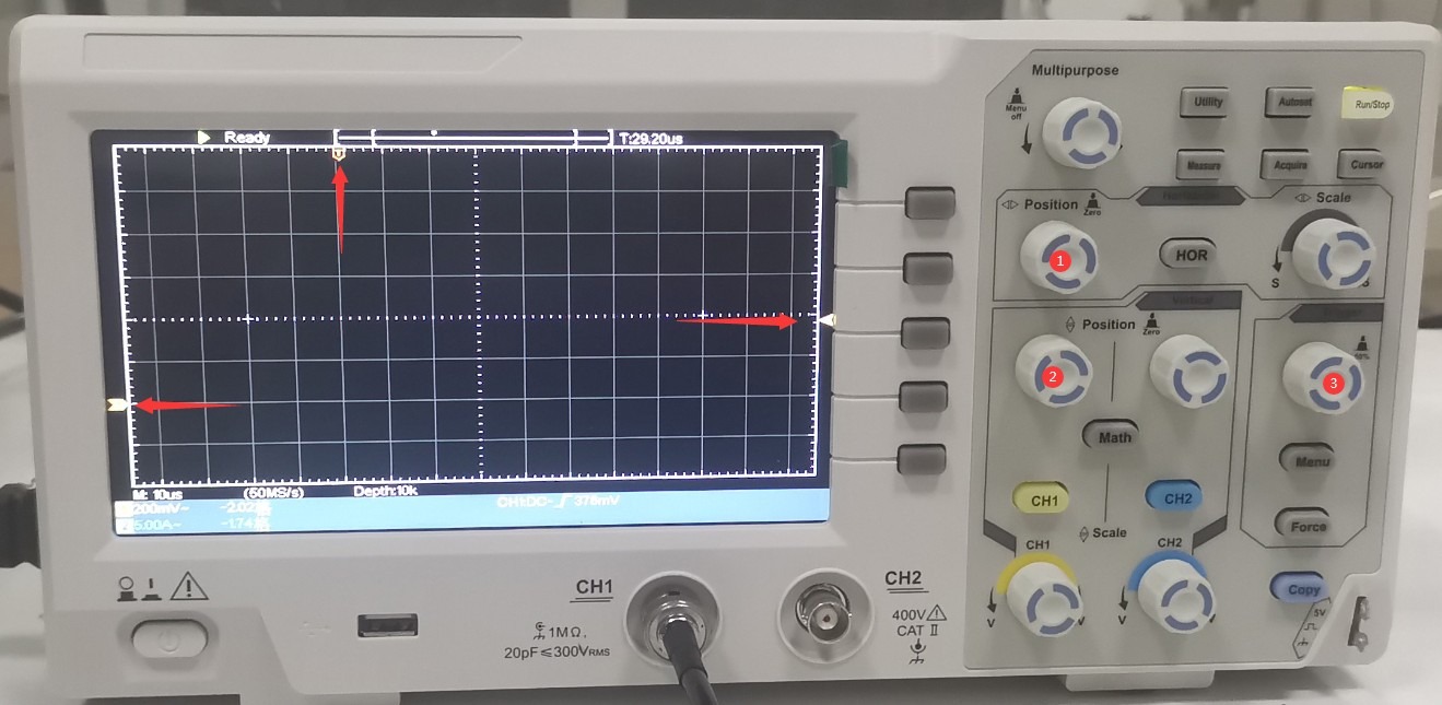
Refer to Figures 7–8. Turn knobs ① (left/right) and ② (up/down) to adjust the waveform display to the appropriate position shown in the figure. Turn knob ③ (“Trigger”) to adjust the level to approximately the middle position.
Gambar 7–8
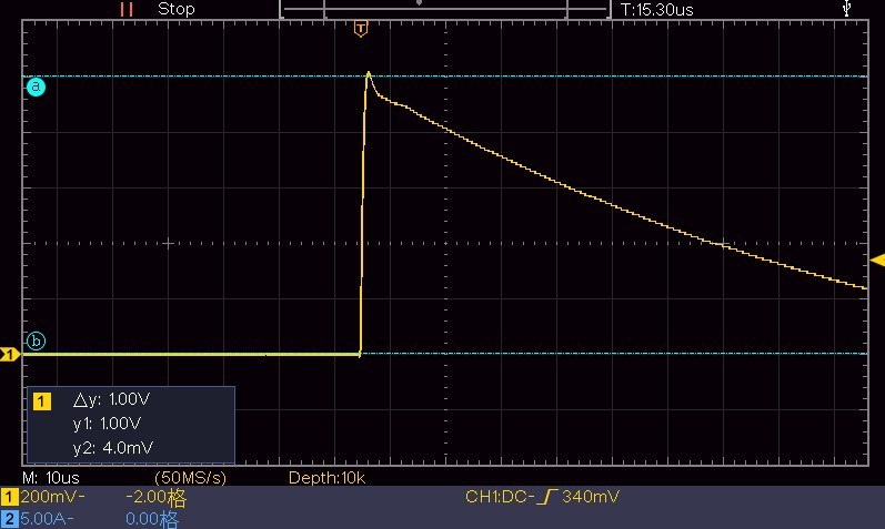
For the lightning surge test on the touchscreen, do not click “EUT Power”; instead, click “Start” directly. As shown in Figures 7–9, each time a surge is output, the oscilloscope will capture a surge voltage waveform as illustrated below. Use the horizontal cursor to verify the surge output voltage. Since the Surge Generator is set to 1 kV, the oscilloscope should display a reading of 1 V.
Gambar 7–9
Use the vertical cursor to confirm the surge half-width time; see Figure 7-10.
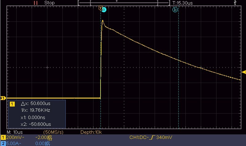
Gambar 7–10
Set the time base to 1 µs, leaving all other settings unchanged. Wait for the next surge output, then use the vertical cursor to determine the rise time of the surge, as shown in Figure 7-11.
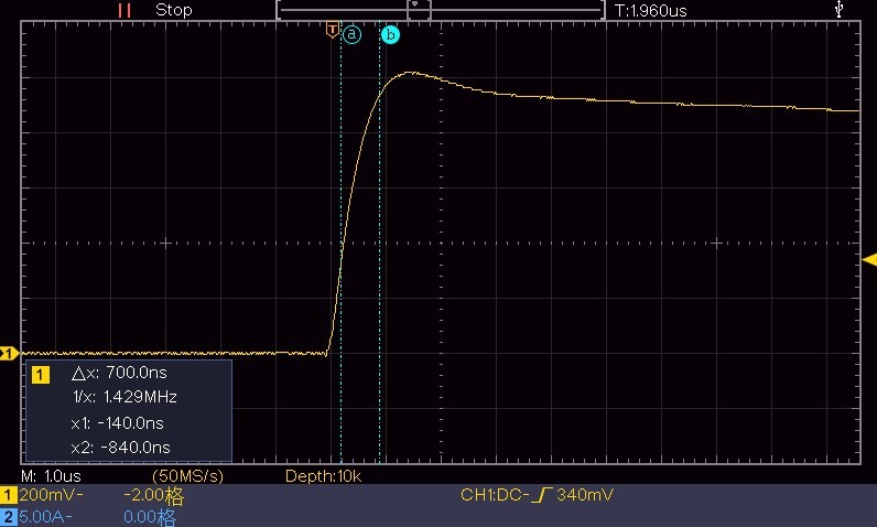
Gambar-7 11
7.1.1.2 Melihat Bentuk Gelombang Arus Lonjakan
Keep the Surge Generator settings unchanged. ① Connect the coaxial cable to the “CRO-I” port to prepare for monitoring the surge current waveform. ② Short-circuit L and N to ensure a complete short-circuit condition. See Figure 7-12.
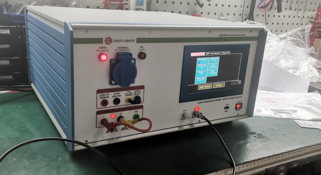
Gambar-7 12
The impedance between L and N in differential mode is 2 Ω, so the vertical scale of the oscilloscope is set to 1/2/5 = 100 mV. The horizontal scale is set to 5 μs. The other settings are the same as when viewing voltage waveforms. The same procedure is used to measure the output surge. The oscilloscope displays the waveform shown in Figure 7-13.
Note: Here, the current is determined using the method for measuring voltage. The actual current is 1000 V / 1000 / 2 Ω = 500 mA, which corresponds to the 500 mV shown in the figure below.
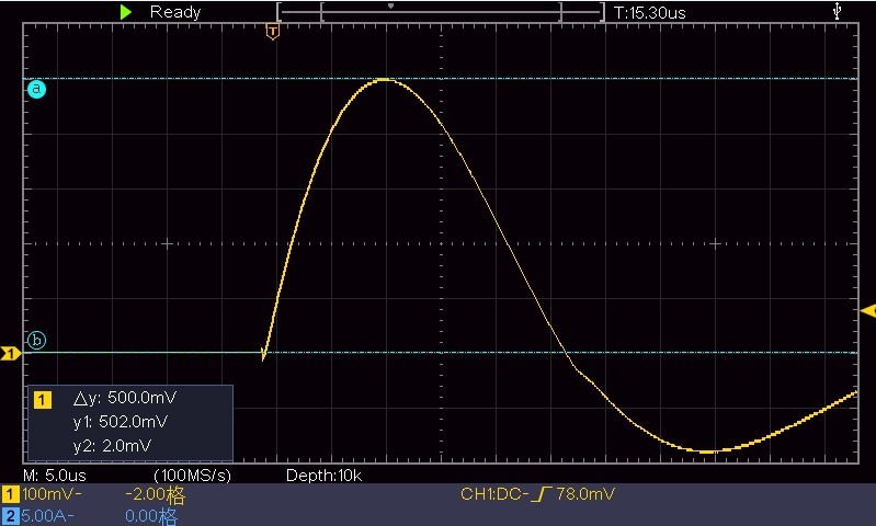
Gambar-7 13
To view the half-width, see Figure 7-14.
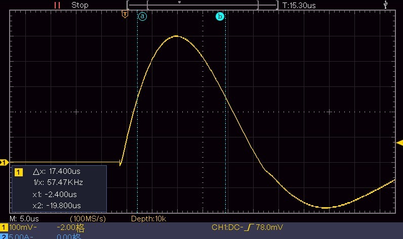
Gambar-7 14
See Figure 7-15 for the leading edge time.
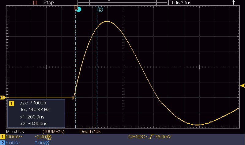
Gambar-7 15
7.1.2 Menggunakan Port Output CDN
The built-in digital oscilloscope and CRO port are both provided to make it easier for users to view waveforms. However, if you need to calibrate the device, you must provide your own high-voltage probe and connect the oscilloscope directly to the CDN output port on the front panel of the surge generator. Refer to Section 7.1.1 and the scale of the high-voltage probe you are using when operating the oscilloscope.
7.2 Menggunakan Tabung Pembuangan
Tabung pelepasan dapat digunakan untuk memverifikasi dengan mudah apakah suatu perangkat menghasilkan lonjakan tegangan.
Connect the discharge tube to the Surge Generator as the EUT. For the Surge Generator’s program interface settings and discharge tube connection, refer to Figure 7-16:
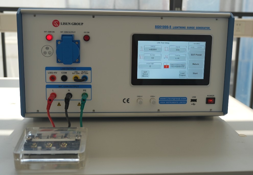
Gambar-7 16
Do not click to turn on “EUT Power”; instead, click “Start” directly to begin the surge test. See Figure 7-17:
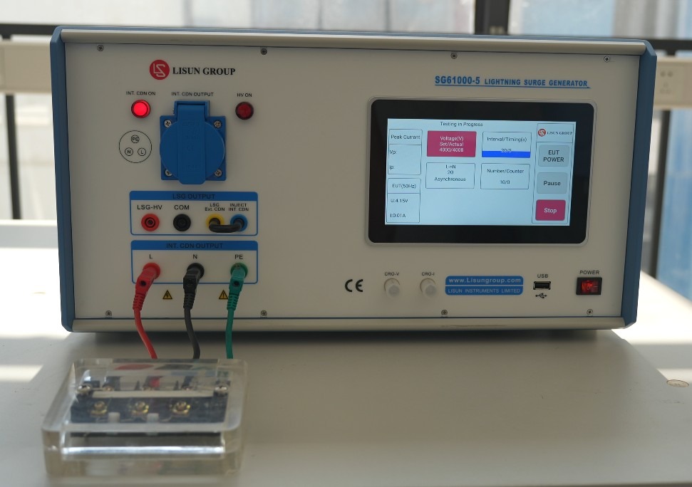
Gambar-7 17
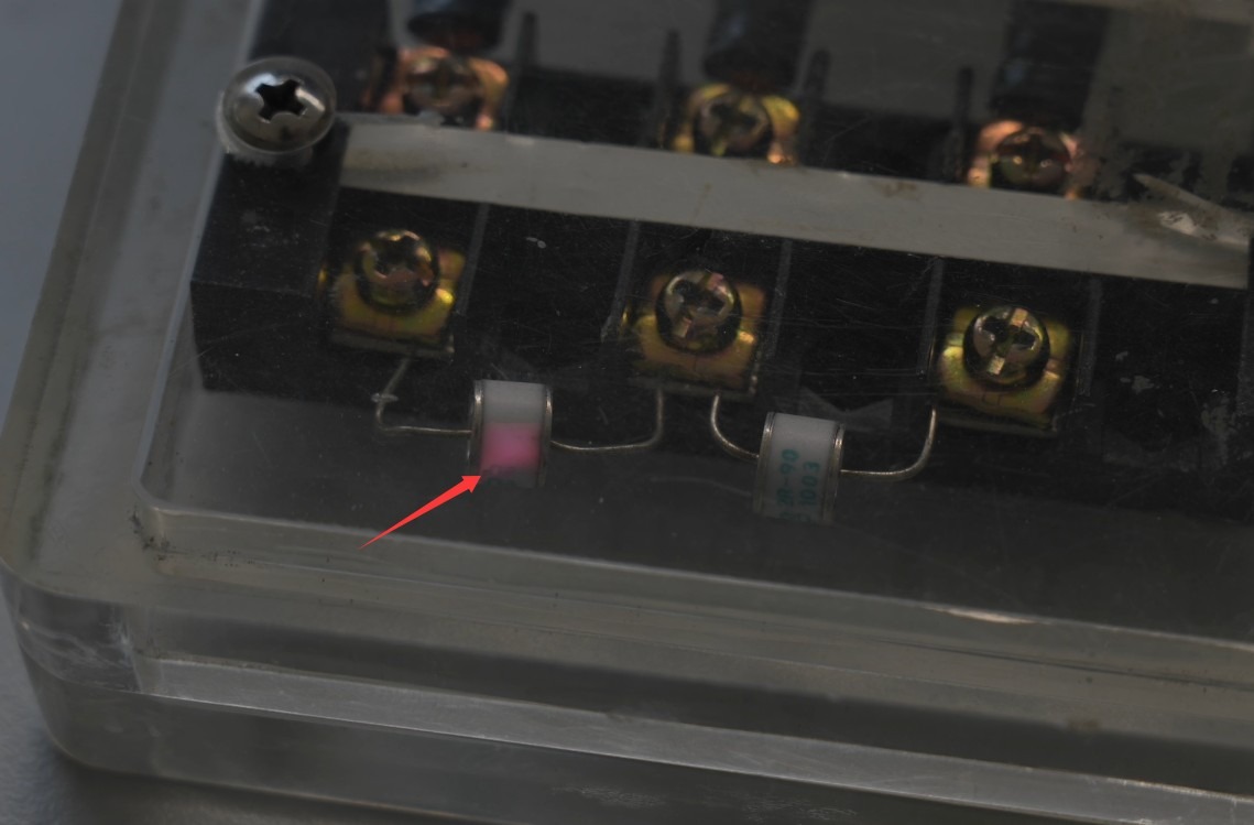
When the surge is output, the discharge tube will flash; please dim the lights in the room to make it easier to observe. See Figure 7-18:
Gambar-7 18
This indicates that the device is indeed producing an output surge. If the discharge tube does not flash, please contact customer service.
8. Pemecahan Masalah dan Penyelesaian Masalah Umum
8.1 Perangkat tidak mau menyala
Gejala: Setelah menyalakan sakelar daya, perangkat tidak merespons (lampu indikator tidak menyala, dan kipas tidak berputar).
Kemungkinan penyebabnya: ① Kabel daya tidak terhubung dengan benar atau rusak; ② Tegangan suplai tidak normal; ③ Sekring putus; ④ Varistor (MOV) terbakar.
Troubleshooting: Ensure the power cord is intact and securely connected. Power supply issues—such as unstable voltage, excessively high voltage, or harmonic interference—can cause the fuse or varistor to blow. It is recommended to use a voltage-stabilized, clean sine-wave AC power supply to power the device. Replace the fuse or varistor with one of the same type.
For the fuse locations, see Figure 8-1:
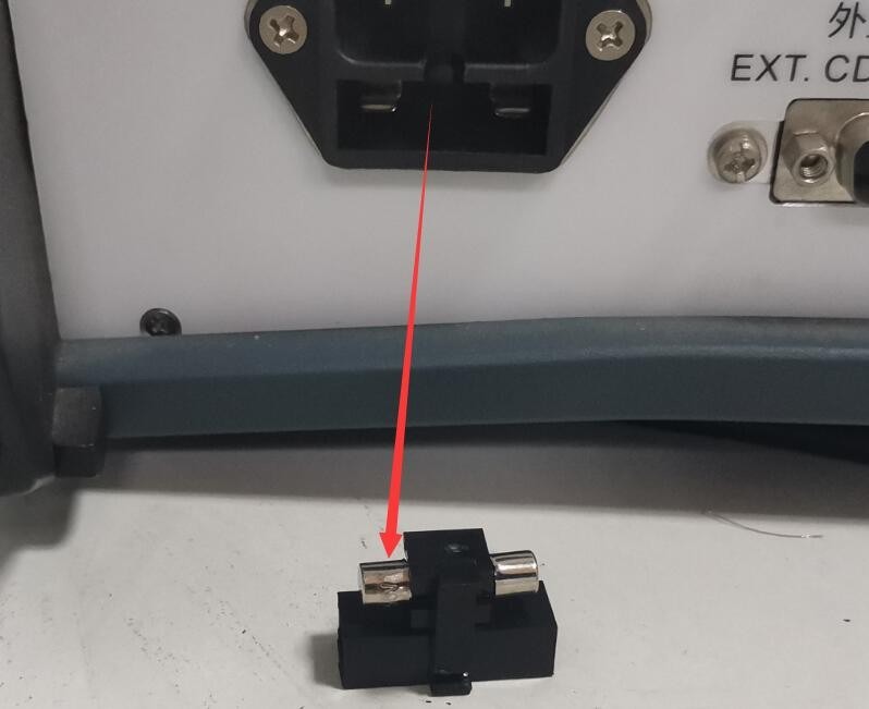
Gambar-8 1
See Figure 8-2 for the location of the MOV (metal-oxide varistor) inside the filtered power supply:
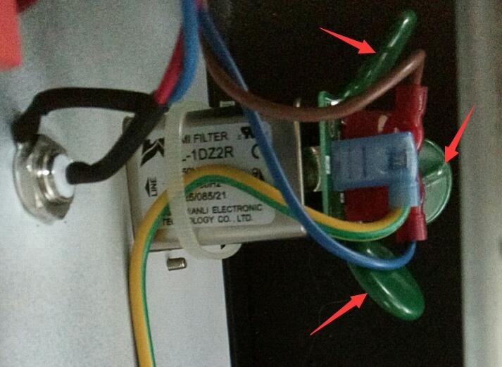
Gambar-8 2
8.2 Circuit Breaker Trip in the Laboratory
Symptom: When a surge is output, the laboratory ground-fault circuit interrupter trips.
Kemungkinan penyebab: Transformator isolasi tidak terhubung.
Prosedur: Hubungkan Transformator Isolasi seperti yang dijelaskan pada Bagian 3.1. Pengujian lonjakan arus menghasilkan arus pulsa sesaat yang besar; jika Transformator Isolasi tidak dihubungkan, hal itu dapat menyebabkan pemutus sirkuit gangguan tanah laboratorium (ground-fault circuit interrupter) mati.
8.3 Restart Perangkat Otomatis
Gejala: Perangkat akan otomatis memulai ulang saat terjadi lonjakan daya.
Kemungkinan penyebab: Kabel ground tidak terhubung dengan benar.
Solusi: Lihat Bagian 3.1. Hubungkan terminal pentanahan PGND di bagian belakang host ke ground, dan pastikan resistansi pentanahan ≤4Ω; jika tidak, tegangan tinggi mungkin tidak dapat dibuang dengan aman, menyebabkan perangkat secara otomatis memulai ulang.
8.4 Uji Sudut Fase Lonjakan Gagal
Symptom: The synchronization phase angle was set, but the surge test was not performed according to the corresponding phase angle.
Possible cause: The EUT power is not turned on.
Prosedur: EUT (Equipment Under Test) harus diberi daya oleh sumber AC, dan harus dinyalakan selama pengujian agar generator lonjakan daya dapat mendeteksi bentuk gelombang daya EUT dan melakukan uji lonjakan daya sesuai dengan sudut fasa yang telah ditetapkan.
8.5 Bentuk gelombang mengandung interferensi.
Symptom: When using the built-in digital oscilloscope or the CRO port to examine a standard surge waveform, zooming in on the waveform reveals some noise. See Figures 8-3 and 8-4:
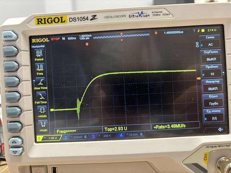
Gambar-8 3
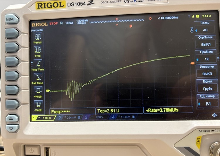
Gambar-8 4
Possible cause: The built-in digital oscilloscope and CRO port are intended to make it convenient for users to quickly and easily obtain waveform data, but they may generate a small amount of noise.
Procedure: If you need to obtain the actual output waveform of the surge generator, or if you wish to calibrate the device, use an oscilloscope and a high-voltage probe to directly inspect the waveform at the CDN output terminal, as shown in Figures 8-5 and 8-6:
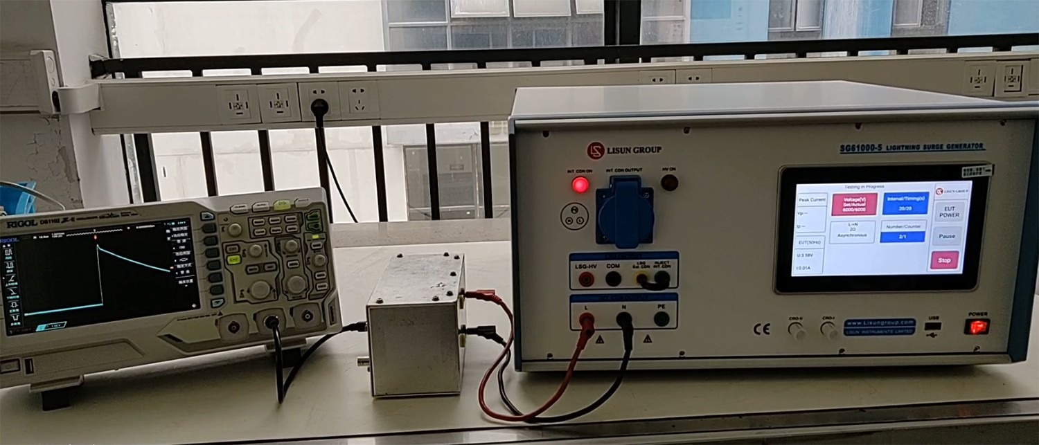
Gambar-8 5
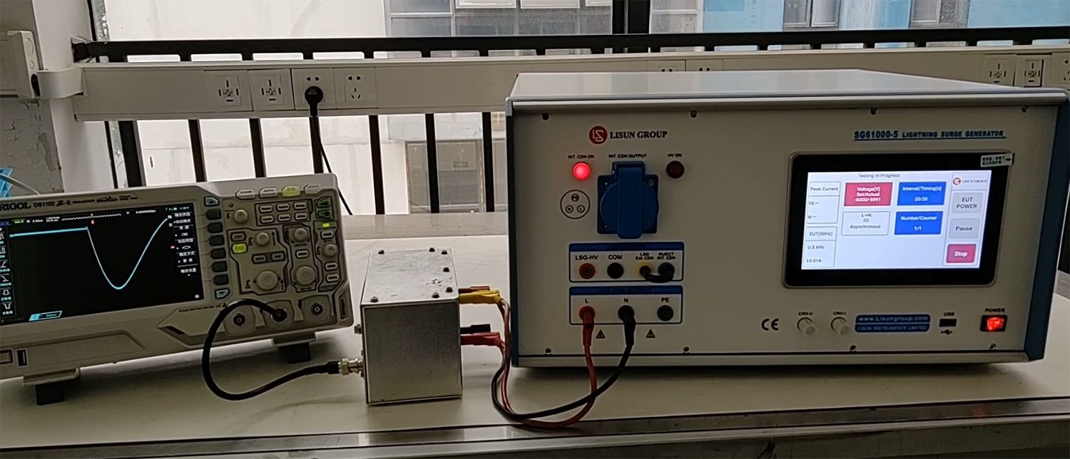
Gambar-8 6