
 Inggris
 中文简体
中文简体 Русский
 Español
 Português
 Türkçe
 العربية
 Deutsch
 Polski
 Italiano
 Français
 한국어
한국어 ไทย
ไทย Tiếng Việt
 日本語
日本語





























Alat Uji Nyala Api Kawat dan Kabel
Pengguna manual
berlaku LISUN Model: RSB-WC1
1. Membuka Kemasan dan Mengenal Peralatan Secara Dasar
1.1 Spesifikasi Teknis Utama
| LISUN Pilih Model | RSB-WC | RSB-WC1 | RSB-WC2 |
| Incinerator Cabinet Dimensions (W x H x D) | 300 × 1200 × 450 mm | 300 × 1300 × 450 mm | |
| Fume Hood Dimensions (W x H x D) | N / A | 930 × 1680 × 720 mm | N / A |
| Standar Kompatibilitas | Sesuai dengan seri GB/T 18380, seri IEC 60332, dan lainnya. | Sesuai dengan GB/T 5169.14 (IEC 60695-11-2); RSB-WC complies with the following standards | Complies with GB/T 20041.1 Clause 13.1.3 (IEC 61368-1 Clause 13.1.3) |
| Jenis Spesimen | Kabel dan kawat berisolasi konduktor tunggal | ||
| Panjang Spesimen | 600 ± 25 mm | ||
| Spesifikasi Spesimen | Diameter konduktor > 0.8 mm atau luas penampang > 0.5 mm² | ||
| Kekuatan Pembakar | 1 kW (api premix nominal) | ||
| Tipe gas | Propana industri dengan kemurnian tinggi (≥95%; disediakan oleh pengguna) | ||
| Rentang Aliran Gas | 0.1–1 L/min (optional electronic gas flow meter) | ||
| Rentang Aliran Udara | 3–30 L/min (optional electronic gas flow meter) | ||
| Rentang Pengaturan Waktu Pembakaran | 0.1–999.9 s (continuously adjustable, digital display) | ||
| Bahan tubuh | Struktur baja berlapis suhu tinggi tahan panas dan tahan korosi, sehingga cocok untuk lingkungan pengujian suhu tinggi jangka panjang. | ||
| Tampilan Operasi | Layar sentuh LCD ekstra besar eksklusif + lampu indikator yang jelas | ||
1.2 Membuka Kemasan dan Memeriksa Isinya
1.2.1 Membuka Kemasan dan Pemeriksaan Visual
When unpacking the equipment, handle it gently to avoid scratching the exterior casing with sharp tools. After unpacking, first inspect the exterior of the main unit to ensure there is no visible deformation, dents, or peeling paint, and that the panel instruments and buttons are not damaged or loose. If you find any damage or deformation to the equipment or its accessories, do not power it on or use it.
Buka pintu ruang uji dan periksa apakah ada komponen internal yang terlepas selama pengiriman atau apakah ada kelainan lain.
Jika Anda menemukan masalah, segera hubungi kami.
1.2.2 Host dan Aksesoris
Wire and cable Flame Tester fume hood (with built-in Flame Test Chamber): 1 unit.
Control cabinet for the Wire and Cable Flame Tester: 1 unit.
Standard accessories are as follows: ① Exhaust pipe; ② Compressed air pipe; ③ Propane gas pipe; ④ Power connection cable between the control cabinet and the fume hood;⑤ Connection cables between the control cabinet and the fume hood thermocouples; ⑥ Temperature-rising copper block and its thermocouple wiring; ⑦ Clamps for securing the exhaust pipe; ⑧ Power cord; ⑨ Sample tray; ⑩ Gauges.
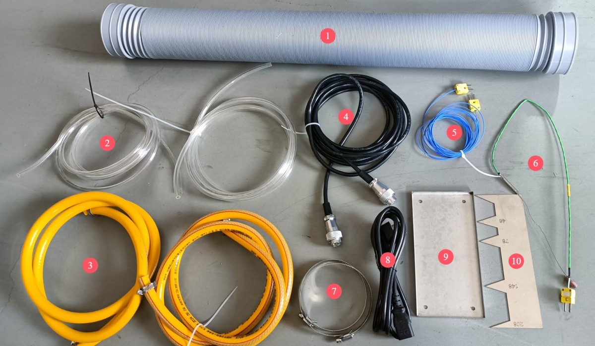
Gambar 1
Pengujian ini memerlukan propana kelas teknis dengan kemurnian ≥95%, yang harus disediakan oleh pengguna.
Tes ini membutuhkan kompresor udara, yang dapat dibeli dari LISUN or provided by the user. If you are providing your own, please refer to the following specifications: pressure, 0.5 to 1 MPa; air storage capacity, 10 L multiplied by the number of minutes of continuous use required.
Catatan: Tautan unduhan untuk manual pengguna elektronik, kartu garansi, dan dokumen lainnya telah dikirim melalui email. Silakan unduh sesegera mungkin. Jika Anda melewatkan email tersebut, jangan ragu untuk menghubungi kami untuk meminta tautan unduhan lagi.
1.3 Deskripsi Struktur Peralatan
1.3.1 Front of the Fume Hood
① Fume hood; ② Combustion chamber; ③ Sample holder; ④ Bunsen burner (angle adjustable); ⑤ Omega Type K thermocouple socket (required for calibrating the flame rise time);⑥ Test chamber door; ⑦ Exhaust vent, 100 mm in diameter, securely connected via an exhaust pipe extending to the outdoors; ⑧ Push-pull rod, used to control the position of the Bunsen burner.
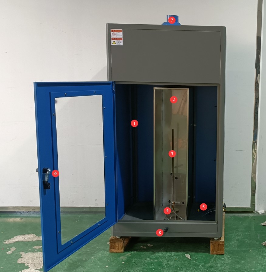
Gambar 2
1.3.2 Front of the Control Cabinet
① Touchscreen; ② Power controls, circuit breaker, and power on/off buttons; ③ Propane gas flow meter and flow control knob, pressure gauge and pressure control knob; ④ Air compressor air flow meter and flow control knob, pressure gauge and pressure control knob.
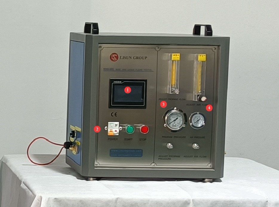
Gambar 3
1.3.2 Right Side of the Control Cabinet
① Propane gas inlet: Use a gas hose with an inner diameter of 10 mm; ② Compressed air inlet: Use a gas hose with an outer diameter of 8 mm; ③ Power cord socket.
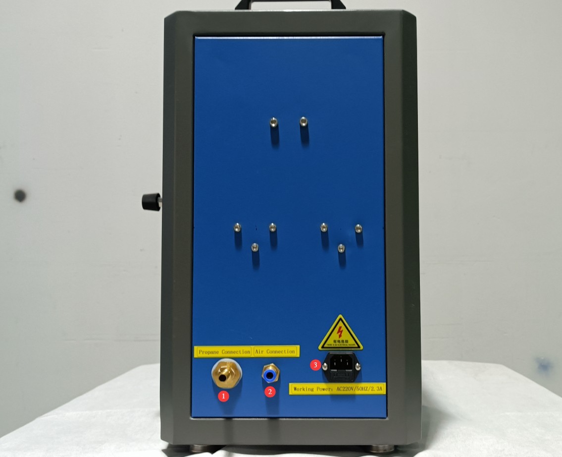
Gambar 4
1.3.3 Connection Between the Fume Hood and the Control Cabinet
Simply connect them one-to-one based on the labels and interface types.
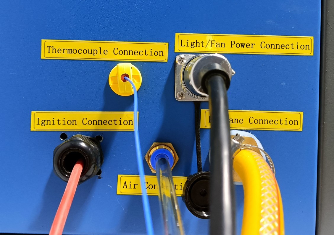
Gambar 4.1
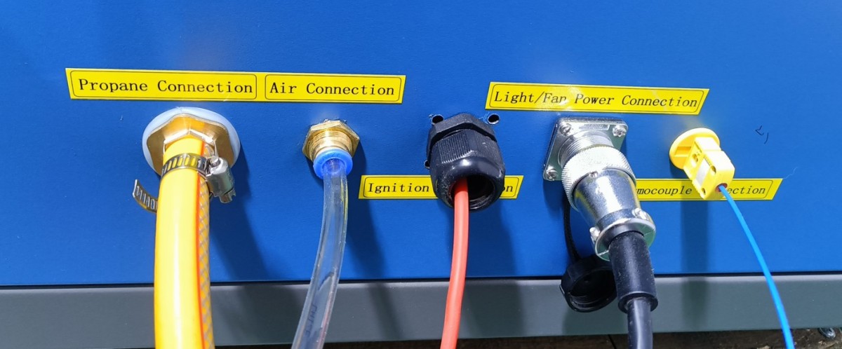
Gambar 4.2
2. Tindakan Pencegahan Keamanan
2.1 Keamanan Listrik
2.1.1 Koneksi Daya
Daya listrik satu fasa 220V; stopkontak harus memenuhi standar keselamatan, memiliki pentanahan yang tepat, dan memiliki arus nominal yang sesuai dengan daya peralatan (disarankan untuk memasang pemutus sirkuit khusus).
2.1.2 Spesifikasi Pembumian
The equipment must be properly grounded, with a ground resistance of ≤4 Ω. Do not use gas pipes, non-metallic water pipes, or the neutral wire as a substitute for the ground wire. After grounding is complete, use a Grounding Resistance Tester to measure the ground resistance. Power may only be applied after confirming that the resistance meets the requirements, to prevent electric shock, equipment malfunctions, or measurement errors caused by poor grounding.
2.1.3 Kontraindikasi untuk Prosedur
Sebelum melakukan pemasangan kabel, pemeriksaan, atau perawatan peralatan, Anda harus memutuskan aliran listrik utama ke peralatan dan memastikan tidak ada tegangan sisa sebelum melanjutkan;
Jangan mengoperasikan sakelar daya peralatan, layar sentuh, atau tombol instrumen dengan tangan basah untuk menghindari risiko sengatan listrik;
Jangan meletakkan benda asing apa pun (seperti perkakas atau kertas) di dalam kabinet kontrol listrik untuk mencegah debu atau benda asing menyebabkan korsleting atau merusak komponen;
Jangan mencolokkan atau mencabut kabel daya atau kabel sinyal saat peralatan sedang beroperasi untuk mencegah korsleting yang dapat merusak pengontrol atau komponen listrik.
2.2 Keselamatan Operasional
2.2.1 Keselamatan Operasional
While the equipment is in operation, non-professionals are prohibited from disassembling or repairing it. In the event of a malfunction, contact after-sales service personnel or operate the equipment only under the guidance of a technician;
The High Temperature Chamber door must be closed during testing. Observe the test process through the chamber viewing window to avoid burns from high-temperature radiation or sparks from burning materials;
In the event of a malfunction or abnormality, immediately stop the test, shut off the power and gas supply, and troubleshoot the problem (see “Chapter 9: Troubleshooting and Handling Common Malfunctions”). Do not force the equipment to start up; operating the equipment before the malfunction has been resolved may cause further damage to the equipment.
2.2.2 Perilaku yang Dilarang
Do not use propane gas with a purity lower than 95% to avoid affecting flame stability and test accuracy;
Jangan membuka pintu kabinet kontrol saat peralatan sedang beroperasi untuk menghindari menyentuh komponen tegangan tinggi di dalamnya dan menyebabkan sengatan listrik;
Jangan membongkar komponen inti tanpa izin; memodifikasi peralatan akan membatalkan garansi dan dapat mengakibatkan insiden keselamatan;
Do not place heavy objects (such as tools or accessories) on top of the equipment to avoid damaging the equipment panel or impairing heat dissipation;
Do not stack flammable items (such as cardboard boxes, plastic wrap, etc.) around the equipment.
2.3 Keselamatan Lingkungan
2.3.1 Persyaratan Instalasi
Peralatan harus dipasang di ruangan ber-AC di mana suhu lingkungan dijaga antara 5°C dan 25°C dan kelembaban relatif ≤85%. Jika kelembaban lingkungan tinggi, kondensasi dapat terbentuk di dekat pintu peralatan dan port pengujian; dalam kasus seperti itu, tingkatkan ventilasi ruangan atau gunakan alat pengering udara (dehumidifier);
The installation site must be free of high concentrations of dust, corrosive gases (such as sulfur dioxide and chlorine), and flammable or explosive atmospheres. Direct sunlight must not be allowed to shine on the equipment to prevent corrosion of the equipment housing and aging of electrical components;
Penyimpanan bahan yang mudah terbakar dan meledak (seperti alkohol, bensin, dll.) dilarang keras di area pengujian untuk mencegah risiko kebakaran atau ledakan;
Propane gas is highly flammable. Store it at a temperature of 40°C or lower, and avoid direct sunlight, violent impacts, or proximity to sources of ignition;
The work area is equipped with fire extinguishers (dry powder or carbon dioxide), and operators are familiar with how to use them;
Keep the device away from locations with significant fluctuations in ambient temperature, such as near vents or indoor entrances, to prevent the device’s temperature control accuracy from being affected;
Jauhi sumber gangguan medan magnet dan listrik yang kuat (seperti motor listrik besar dan peralatan tegangan tinggi).
2.3.2 Persyaratan Ruang
The distance between the equipment enclosure and walls, as well as surrounding fixtures (such as other testing equipment and shelving), must be at least 1000 mm to facilitate maintenance;
Setidaknya harus ada ruang selebar 2000 mm pada bukaan pintu peralatan untuk memastikan pintu dapat dibuka ke segala arah, sehingga memudahkan penempatan dan pengambilan sampel.
2.3.3 Penempatan Horizontal
The device must be placed on a flat surface. Use a level to ensure the device is level: Place the level on the top surface of the device and make sure the bubble is centered. Note: The device has four adjustable legs that can be used to level it. Once leveled, ensure that all four legs are firmly in contact with the surface.
If the equipment is tilted, the angle of the Bunsen burner will be inaccurate, and this may cause the sample, Bunsen burner, and temperature-rising copper block to shift out of position, affecting the test results.
2.4 Lainnya
Untuk hal-hal yang tidak tercakup dalam panduan ini, harap berhati-hati atau hubungi kami.
3. Pengantar Program Layar Sentuh
3.1 Antarmuka Pengguna
① Burn time; ② Afterglow time; ③ PV is the current value; ④ SV is the set value; ⑤ Lighting: Used to turn on the lighting inside the test chamber for easier observation; ⑥ Fan: Used to exhaust smoke generated inside the test chamber after the test is complete;⑦ Ignition; ⑧ Air supply on; ⑨ Propane gas supply on; ⑩ Start test;⑪ Reset: Click after the test is complete or before the next test begins to clear the test data; ⑫ Afterglow Pause: Used to record the time it takes for the sample’s afterglow to extinguish; ⑬ Parameter Settings; ⑭ Temperature Calibration: Performs a temperature rise test.
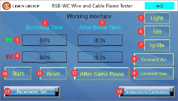
Gambar 5
3.2 Antarmuka Pengaturan Parameter
① Pengaturan waktu pembakaran; ② Pengaturan waktu cahaya setelah nyala.
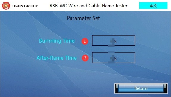
Gambar 6
3.3 Temperature Calibration Interface
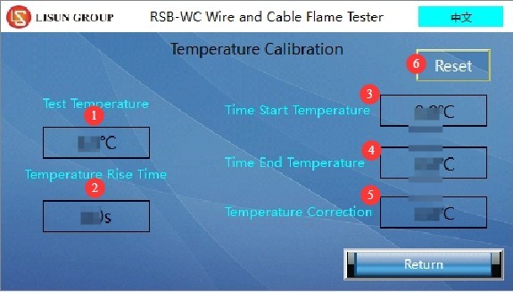
① Current temperature display; ② Temperature rise time display; ③ Start temperature setting; ④ End temperature setting; ⑤ Temperature correction—no changes needed; ⑥ Reset—tap to clear the current data and retest the temperature rise time.
Gambar 7
Note: Common standards (such as GB/T 5169.14 and IEC 60695-11-2) require that the temperature rise test begin at 100°C and end at 700°C. Users may also set different start and end temperatures in accordance with specific standards.
4. Persiapan Sebelum Ujian
4.1 Environmental and Equipment Inspection
4.1.1 Persyaratan Lingkungan Pengujian
Atur suhu lingkungan sekitar menjadi 23±2°C dan kelembapan relatif menjadi 50±5% untuk mencegah faktor lingkungan memengaruhi hasil pengujian. Catatan: Persyaratan suhu dan kelembapan untuk lingkungan penyimpanan peralatan berbeda dengan persyaratan untuk lingkungan pengoperasiannya.
4.1.2 Sambungan dan Inspeksi Pipa Peralatan
Pastikan pipa pembuangan terhubung dengan aman ke saluran pembuangan peralatan dan memanjang ke luar.
Setelah menghubungkan tabung propana ke peralatan, atur regulator tekanan tabung sedikit di atas 0.1 MPa. Hubungkan kompresor udara, yang menghasilkan udara terkompresi pada tekanan antara 0.5 dan 1 MPa, ke peralatan tersebut.
Check that the propane gas lines and compressed air lines are properly connected and free of leaks, and that the clamps are securely fastened. You can apply soapy water to the joints and watch for bubbles to determine if there are any leaks.
4.2 Menyesuaikan Nyala Api
Adjust the Ben Sheng lamp to a vertical angle.
Pada antarmuka program layar sentuh, tekan tombol “Propane Gas On”, atur secara kasar kenop tekanan propana dan kenop pengukur aliran, lalu tekan dan tahan tombol “Ignition” untuk berhasil menyalakan api. Kemudian atur pengaturan propana ke nilai standar yang ditentukan (tekanan propana: 0.1 MPa; laju aliran: 650 ± 30 mL/menit). Catatan Penting: Minimalkan waktu antara menekan tombol “Propane On” dan penyalaan (kurang dari 5 detik) untuk mencegah penumpukan propana berlebihan di ruang pembakaran, yang dapat menimbulkan bahaya.
Tekan tombol “Air On”, lalu atur kenop pengatur tekanan udara dan kenop pengukur aliran ke nilai standar yang ditentukan (tekanan udara: 0.1 MPa; laju aliran udara: 10 ± 0.5 L/min).
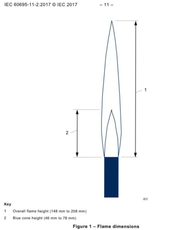
Use a gauge to measure the flame height, and fine-tune the air and propane flow rates separately until the flame meets the test requirements. The flame heights required by the IEC 60695-11-2 (GB/T 5169.14) standard are as follows:
Gambar 8
Alat ukur ini digunakan sebagai berikut; semua dimensi yang tertera di atasnya sesuai dengan standar:
Gambar 9
Once the flame is adjusted, press the “Propane On” button to make it pop out, cutting off the propane gas supply; the flame will automatically go out. Then press the “Air On” button again to shut off the compressed air supply.
No changes need to be made to the propane gas cylinders, air compressors, or any of the adjustment knobs on the front panel of the RSB-WC equipment for the time being, so that combustion tests or temperature calibration can be performed directly later on.
4.3 Praperlakuan dan Pemasangan Sampel
4.3.1 Perlakuan Awal Sampel
Sample Cutting: Cut wire and cable test specimens to a sufficient length in accordance with the standard, and remove any oil or impurities from the surface. Requirements for sample length in the IEC 60695-11-2 (GB/T 5169.14) standard: The test specimen shall be a single length of wire or cable measuring (600 ± 25) mm.
Pengkondisian: Biarkan sampel berada di lingkungan pengujian (23±2°C, kelembapan 50±5%) selama minimal 24 jam.
4.3.2 Sample Installation and Bunsen Burner Adjustment
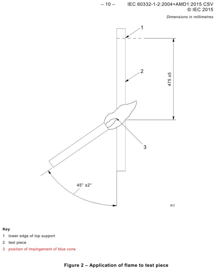
Kabel bulat: Jarak antara titik kontak api dan tepi bawah braket horizontal adalah 475 ± 5 mm;
Kabel pipih: Titik kontak api terletak di tengah bagian pipih, 475 ± 5 mm dari tepi bawah penyangga atas;
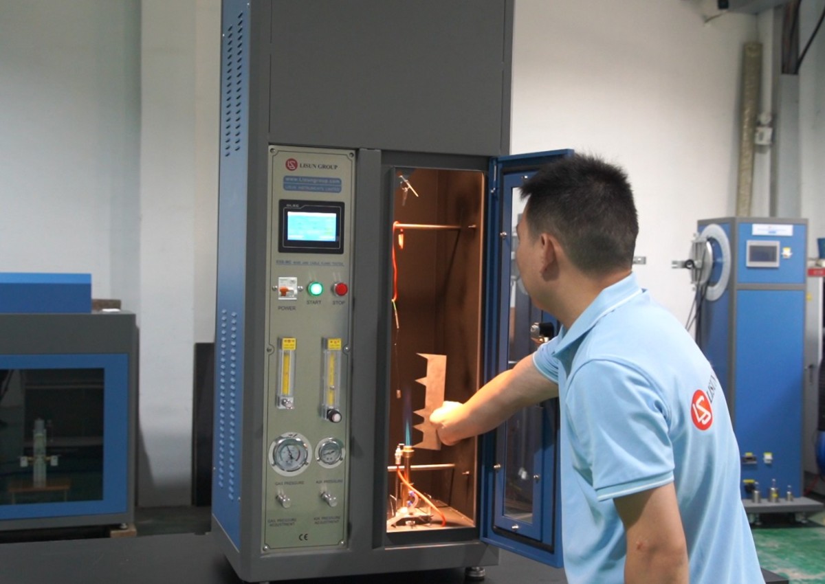
Adjust the angle of the Bunsen burner to 45°, use the push-pull rod to push the Bunsen burner all the way down, and secure the pretreated sample to the sample holder in reference to the Bunsen burner’s position, ensuring the sample is vertical and does not wobble. Use a gauge to confirm the distance between the Bunsen burner and the sample so that the tip of the inner blue cone of the flame just touches the sample surface, as shown in the standard diagram below:
Gambar 11
Letakkan baki pengumpul tepat di bawah sampel untuk mengumpulkan tetesan hasil pembakaran.
5. Prosedur Uji Pembakaran Kabel
5.1 Menetapkan Parameter Uji
Burn Time Setting: Set the burn time based on the equivalent diameter of the sample cable:
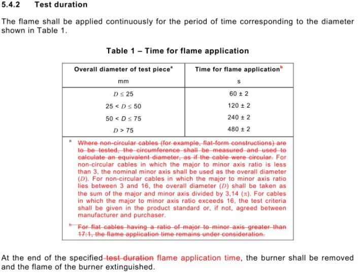
Gambar 12
Konversi Diameter Ekuivalen: Untuk kabel yang tidak berbentuk lingkaran (seperti kabel pipih), ukur kelilingnya dan konversikan ke diameter ekuivalen (dihitung seolah-olah itu adalah kabel berbentuk lingkaran).
Afterglow Time Setting: The standard does not specify a value for afterglow time. If you are conducting tests in accordance with other standards and need to use the afterglow time to calculate the burning rate, please set a reasonable afterglow time.
5.2 Prosedur Uji
First, use the push-pull rod to move the Bunsen burner away from the sample;
Tap “Propane On,” press and hold the “Ignition” button to light the flame, then tap “Air On”; the unit will automatically maintain the flame;
Once the flame has stabilized, use the push-pull rod to slowly move the Bunsen burner to the test position. At the same time, tap “Start Test” on the touchscreen, and the burn time countdown will begin,
During the test, monitor the combustion status of the sample through the observation window and record whether the fire spreads, if there are any dripping materials, and other such phenomena;
Once the burn time has elapsed, the equipment automatically shuts off the propane and air supplies, the flame goes out, and the “afterglow time” begins;
When the sample’s afterglow has completely extinguished, immediately click “Afterglow Pause” and record the afterglow duration.
6. Prosedur Pasca-Ujian
6.1 Pengoperasian Peralatan Setelah Pengujian
6.1.1 Penanganan Aman
After the test is complete, click the “Fan” button to activate the exhaust system and remove smoke and toxic gases from the chamber. Wait at least 5 minutes for the chamber to ventilate before opening the door.
Jika pengujian tidak akan dilanjutkan pada hari itu, matikan peralatan, tangki propana, dan kompresor udara.
6.1.2 Pembersihan Peralatan
After the equipment has cooled, wipe the inner walls of the test chamber, the Bunsen burner, and the sample holders with a dry cloth to remove any combustion residues.
If any burning droplets fall, please clean the drip tray and dispose of the droplets in accordance with environmental protection requirements.
6.2 Pencatatan dan Pengorganisasian Data Eksperimental
The test report must include the following:
Jenis sampel, spesifikasi, metode persiapan, dan kondisi pra-perlakuan;
Number of test specimens, installation locations, and flame application points;
Parameter pengujian: waktu pembakaran, waktu pendaran setelah pembakaran;
Test Observations: Whether the sample ignites, the duration of the afterglow, and whether the sample is completely burned;
Test Results: Passed—the distance between the lower edge of the upper support and the starting point of the charred area is >50 mm; Criteria for Failure: The fire extends downward to a distance greater than 540 mm from the lower edge of the upper support; Re-testing Rules: If the initial test fails, new samples must be prepared for two re-tests. If both re-tests pass, the batch of samples is deemed to have passed.
6.3 Persiapan Sampel
If samples are not completely burned after testing, they should be classified and disposed of as waste. If they contain toxic or flammable residues, they must be sealed and handed over to a specialized agency for disposal.
Retain a portion of the samples after testing for subsequent review or to verify the results.
6.4 Penyimpanan Peralatan
6.4.1 Persyaratan Penyimpanan Jangka Pendek
If the equipment is for everyday use, no special handling is required.
6.4.2 Persyaratan untuk Penyimpanan Jangka Panjang
If the device will not be used for an extended period (more than one month), please unplug the power cord and cover the device with a dust cover to prevent dust buildup.
The device should be powered on once a month for just half an hour to prevent the electrical components (such as capacitors and contactors) from deteriorating.
7. Kalibrasi Suhu
7.1 Calibration Preparation
7.1.1 Calibration Conditions
Suhu lingkungan: 23 ± 2 °C; kelembapan relatif: 50 ± 5%; tidak ada gangguan aliran udara;
The calibration copper block and thermocouple are in good condition; the copper block is made of Cu-ETP UNS C11000.
7.1.2 Basis for Calibration
Requirements regarding the temperature rise time in the IEC 60695-11-2 (GB/T 5169.14) standard: The time required for a copper block to heat up from 100°C ± 5°C to 700°C ± 3°C shall be 46 s ± 6 s.
Prosedur 7.2
Atur nyala api sesuai dengan prosedur di Bagian 4.2, lalu padamkan nyala api.
Insert the thermocouple plug into the Omega Type K thermocouple socket provided in the test chamber, and secure it using the standard copper block 95 mm directly above the burner nozzle, ensuring that the flame fully contacts the copper block.
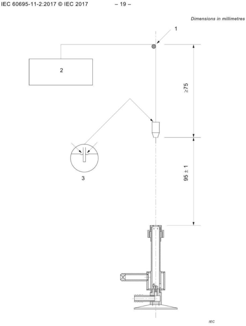
Gambar 14
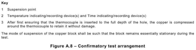
Gambar 15
Close the test chamber door, enter the temperature calibration interface, and set the following: start temperature to 100°C, end temperature to 700°C, and leave the temperature correction at the default value. Click “Reset” to clear the historical data.
Return to the operating screen, tap “Air On” and “Propane On,” then press and hold “Ignition.”
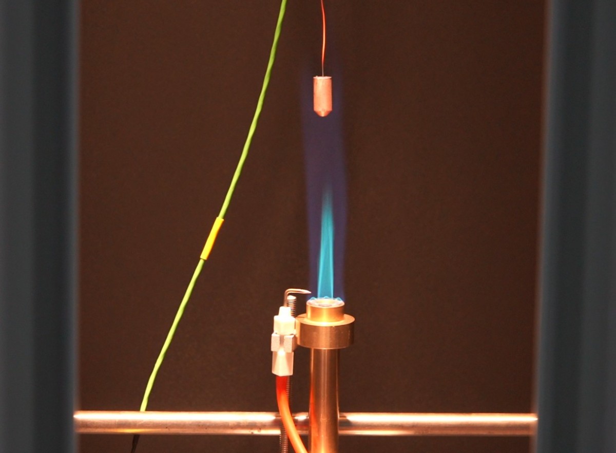
Gambar 16
Return to the temperature calibration screen and observe the current temperature and heating time displayed on the touchscreen. The timer starts automatically when the copper block reaches 100°C and stops automatically when it reaches 700°C.
Ulangi kalibrasi sebanyak tiga kali, biarkan blok tembaga mendingin secara alami hingga di bawah 50°C setelah setiap pengukuran.
Hitung waktu rata-rata kenaikan suhu berdasarkan tiga pengukuran; jika berada dalam rentang 46 s ± 6 s, nyala api memenuhi persyaratan. Kalibrasi suhu tunggal sudah cukup untuk setiap tangki gas propana.
7.3 Menangani Penyimpangan Suhu Kalibrasi
The temperature rise time is used to determine whether the propane gas you are using, the flame being calibrated, and the test conditions meet the standard test requirements. If the temperature rise time is incorrect, it means your test does not meet the standard requirements; it does not indicate that there is a problem with the equipment itself.
8. Perawatan Rutin
| Siklus Pemeliharaan | Proyek Pemeliharaan | Operasi Pemeliharaan |
| Setelah setiap tes | Pembersihan Peralatan | 1. Wipe down the interior and exterior of the test chamber, the viewing window, and the fixtures; 2. Clean up any drips and soot from the drip tray |
| Seminggu sekali | Pemeliharaan bantalan | Wipe down the linear bearing rail with a cloth dipped in organic oil to ensure that the moving parts operate smoothly. |
| Sekali sebulan | Inspeksi Sistem Gas | 1. Periksa sambungan gas untuk kebocoran (menggunakan air sabun); 2. Periksa selang untuk tanda-tanda penuaan dan ganti jika perlu; 3. Bersihkan meteran aliran dan pengukur tekanan diferensial. |
| Setiap 3 bulan sekali | Kalibrasi Nyala Api | Waktu yang dibutuhkan untuk memanaskan blok tembaga dari 100°C ± 5°C hingga 700°C ± 3°C seharusnya adalah 46 s ± 6 s. |
| Setiap 6 bulan sekali | Pemeriksaan Sistem Kelistrikan | 1. Periksa apakah saluran daya dan terminal pembumian terpasang dengan aman; 2. Ganti sekering yang sudah aus; 3. Uji kinerja sistem pengapian. |
| Sekali setahun | Perawatan Komprehensif | 1. Replace the gas hose and gaskets; 2. Calibrate the touchscreen’s timing accuracy; 3. Inspect the Bunsen burner for wear and replace it if necessary; 4. Contact the supplier to arrange for professional testing and calibration |
9. Pemecahan Masalah dan Penyelesaian Masalah Umum
9.1 Kegagalan Pengapian
| Gejala Kesalahan | Kemungkinan penyebab | Pendekatan |
| No flame when the ignition button is held down | Tabung propana belum dibuka / regulator tekanan belum disetel | Open the main valve on the gas cylinder and adjust the pressure regulator to approximately 0.1 MPa. |
| Propane Flow Too Low/Pipe Blockage | Bilas selang dan atur laju aliran menjadi 650 ± 30 mL/menit. | |
| Ignition Electrode Misalignment | Atur jarum pengapian agar berjarak 3–5 mm dari lubang keluar api. | |
| Kerusakan Pemantik | Contact customer service to have the igniter replaced |
9.2 Tinggi Nyala Api Tidak Memenuhi Standar
| Gejala Kesalahan | Kemungkinan penyebab | Pendekatan |
| Tinggi nyala api total terlalu rendah | Aliran propana tidak mencukupi / Aliran udara berlebihan | Tingkatkan laju aliran propana, kurangi laju aliran udara, dan lakukan pengukuran lagi. |
| Tinggi nyala api secara keseluruhan terlalu tinggi. | Aliran propana berlebihan / Aliran udara tidak mencukupi | Kurangi laju aliran propana, tingkatkan laju aliran udara, dan lakukan pengukuran lagi. |
| Tidak Ada Hati Api Biru | Aliran udara tidak cukup | Increase the airflow and adjust until a blue flame core appears. |
9.3 Waktu Kenaikan Suhu Tidak Memenuhi Persyaratan
| Gejala Kesalahan | Kemungkinan penyebab | Pendekatan |
| Waktu untuk mencapai suhu > 52 detik | Daya nyala api tidak mencukupi / Kontak yang buruk dengan blok tembaga | Readjust the flame height and flow rate, and check that the copper block is securely installed. |
| Waktu pemanasan < 40 detik | Daya nyala api berlebihan / Kesalahan pengukuran suhu pada blok tembaga | Kurangi laju aliran propana, kalibrasi sensor suhu, dan hubungi produsen untuk kalibrasi. |
9.4 Kerusakan Listrik
| Gejala Kegagalan | Kemungkinan penyebab | Pendekatan |
| Tidak ada tampilan pada layar sentuh. | Power Not Connected/Fuse Blown | Periksa sambungan daya dan ganti sekering dengan sekering yang memiliki nilai yang sama. |
| Tombol Tidak Merespons | Kerusakan Layar Sentuh/Koneksi Sirkuit yang Buruk | Restart the device, check the internal wiring, and contact customer service for repairs. |
| Perangkat mati secara otomatis | Overload Protection / Unstable Power Supply Voltage | Check the power supply voltage, avoid operating the device under overload conditions, and restart the device. |
9.5 Other Faults
| Gejala Kesalahan | Kemungkinan penyebab | Pendekatan |
| Asap hasil pembakaran tidak dapat dibuang ke udara. | Saluran pembuangan tersumbat / Kipas rusak | Bersihkan saluran pembuangan, periksa kondisi kerja kipas, dan ganti kipas jika mengalami kerusakan. |
| Sampel tidak diamankan dengan benar. | Penjepit Braket Longgar | Adjust the fixture to ensure the sample is vertical and does not wobble. |
| Penyimpangan Signifikan pada Data Uji | Peralatan tidak rata / Suhu dan kelembapan lingkungan berada di luar kisaran yang ditentukan | Kalibrasi ulang level peralatan dan sesuaikan suhu serta kelembapan lingkungan ke kisaran standar. |