
 Inggris
 中文简体
中文简体 Русский
 Español
 Português
 Türkçe
 العربية
 Deutsch
 Polski
 Italiano
 Français
 한국어
한국어 ไทย
ไทย Tiếng Việt
 日本語
日本語





























Sistem Generator Getaran Elektrodinamik
Pengguna manual
berlaku LISUN Model: LVD-100KG,LVD-100KG-6D
1. Pemahaman Dasar tentang Peralatan
1.1 Parameter Utama
| Spesifikasi/Nomor Model | LVD-100KG | LVD-100KG-6D |
| Direction of Vibration | Vertical and Horizontal Directions | Vertical, horizontal, and longitudinal |
| Vibration Table Dimensions | 500 mm × 500 mm (other sizes available upon request) | |
| Bentuk Gelombang Getaran | Sine Wave (Half-Wave, Full-Wave) | |
| Kontrol Getaran | Fixed Frequency, Frequency Sweep, Programming | |
1.2 Verifikasi Konfigurasi Peralatan
1.2.1 Membongkar
When unpacking the device, handle it gently to avoid scratching the casing with sharp objects. After unpacking, first inspect the exterior of the device to ensure there is no visible deformation or dents, and that the buttons are not damaged or loose. If you notice any abnormalities with the device or its accessories, do not turn it on. Please contact us immediately.
1.2.2 Unit Utama dan Aksesoris
Host (Figure 1-1):
| Jumlah | Note |
| ① | konsul |
| ② | Tabel Getaran |
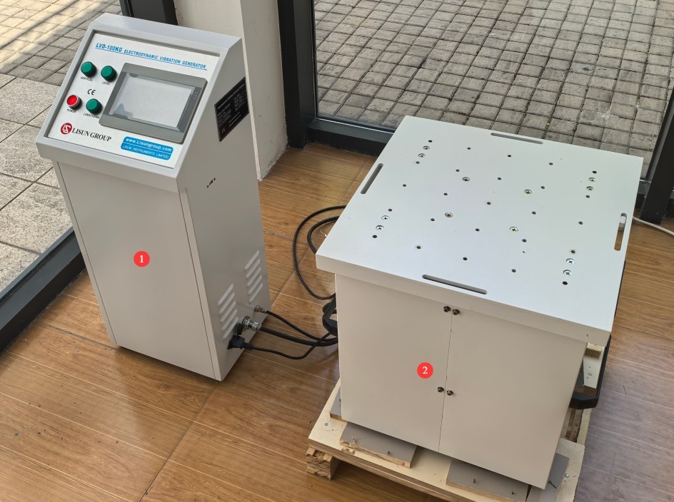
Gambar-1 1
Main Components (Figs. 1–2):
| Jumlah | Note | |
| ① | Handheld Vibration Meter and Accessories | |
| ② | Special mounting bracket for vibration tables, designed to prevent the vibration table from moving during operation | |
| ③ | Tali pengikat | For securing samples |
| ④ | Stud Clamping Device | |
| ⑤ | Kabel Listrik | |
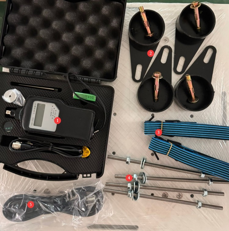
Gambar 1–2
1.2.3 Mengunduh Dokumen Elektronik
Kami telah mengirimkan tautan unduhan untuk manual pengguna elektronik, kartu garansi, dan dokumen lainnya melalui email pada saat pengiriman. Silakan unduh sesegera mungkin. Jika Anda melewatkan email tersebut, Anda dapat menghubungi kami untuk meminta tautan unduhan lagi.
2. Tindakan Pencegahan Keamanan
2.1 Keamanan Listrik
Before connecting the power cord, verify that the supply voltage is AC 220 V ±10% and the frequency is 50 Hz (60 Hz is available upon request; please refer to your device’s nameplate); You must use a three-prong outlet with a protective ground, with a protective ground resistance of ≤4 Ω. Under no circumstances should you cut or disconnect the protective ground wire, as doing so poses a risk of electric shock.
2.2 Keselamatan Lingkungan
The equipment must be installed in an air-conditioned room, with the ambient temperature maintained between 10°C and 35°C and relative humidity ≤ 80%;
The floor must be level, sturdy, and capable of supporting the required load; it must be free of flammable or explosive materials, heavy dust, and strong electromagnetic interference.
2.3 Keselamatan Operasional
The vibration test stand generates strong vibrations during operation; therefore, it is recommended to use it on a solid floor and secure it with a dedicated mounting bracket;
Do not pull, squeeze, or bend the cables; under no circumstances should power or signal cables be plugged in or unplugged while the device is running;
The sample must be securely clamped, with no looseness or displacement, to prevent splashes from injuring people or damaging the equipment;
Do not wear loose-fitting clothing or jewelry; tie back long hair; and wear safety goggles;
To ensure safety, it is recommended to install the equipment in a well-ventilated, separate testing area and to install protective barriers to prevent sample splatter;
When the equipment is in operation, personnel must remain at least 1 meter away from the work surface; reaching out or leaning toward the vibration zone is strictly prohibited;
If you notice unusual noises, odors, smoke, loose samples, or an overload, immediately shut down the control console, troubleshoot the issue, and then try again.
2.4 Lainnya
Untuk hal-hal yang tidak tercakup dalam panduan ini, harap berhati-hati atau hubungi kami.
3. Equipment Overview and Installation
3.1 Introduction to the Console
Lihat Gambar 3-1.
| Jumlah | Note |
| ① | Tombol power |
| ② | Vertical Vibration Indicator Light |
| ③ | Lateral Vibration Indicator Light |
| ④ | Vertical Vibration Indicator Light |
| ⑤ | Touchscreen |
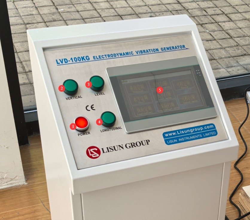
Gambar-3 1
3.2 Introduction to and Installation of the Vibration Test Stand
3.2.1 Introduction to the Vibration Test Stand
Lihat Gambar 3-2.
| Jumlah | Note |
| ① | M8 screw holes, for securing samples with screws |
| ② | Stud holes, which can be used to secure samples with a stud clamping device |
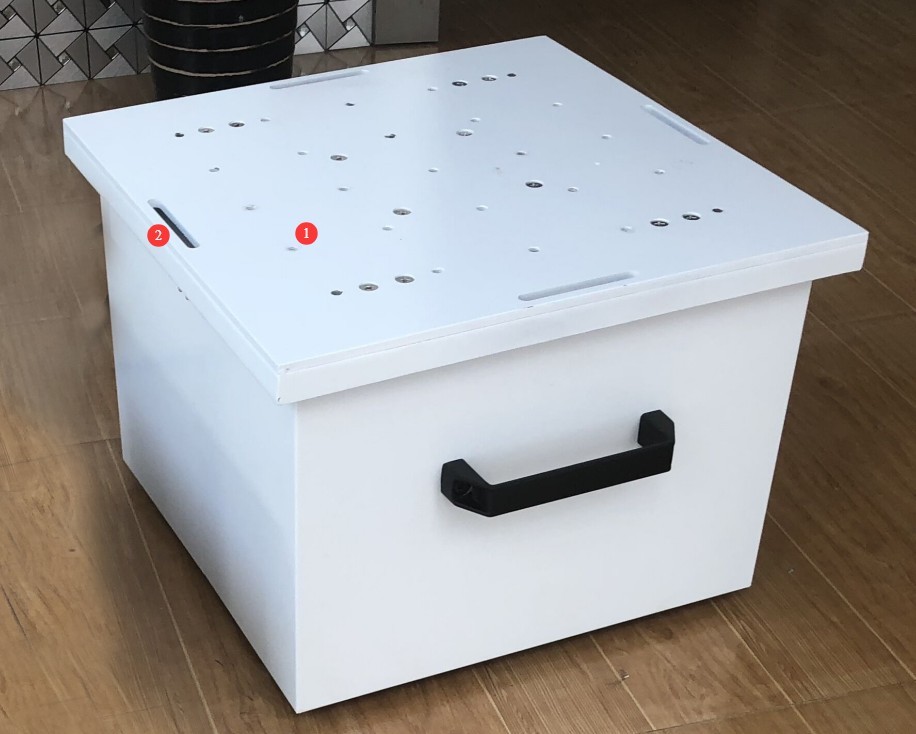
Gambar-3 2
3.2.2 Vibration Table Installation
Secure the vibration table’s mounting bracket to a level surface using expansion screws, then place the four legs of the vibration table securely into the mounting bracket.
3.3 Wiring Between the Control Console and the Vibration Table
Lihat Gambar 3-3.
| Jumlah | Note |
| ① | The vibration test stand includes two cables. |
| ② | Connect the two cables from the vibration table to the control console, pairing them one-to-one. |
| ③ | Soket kabel daya, untuk menghubungkan perangkat ke sumber daya yang sesuai. |
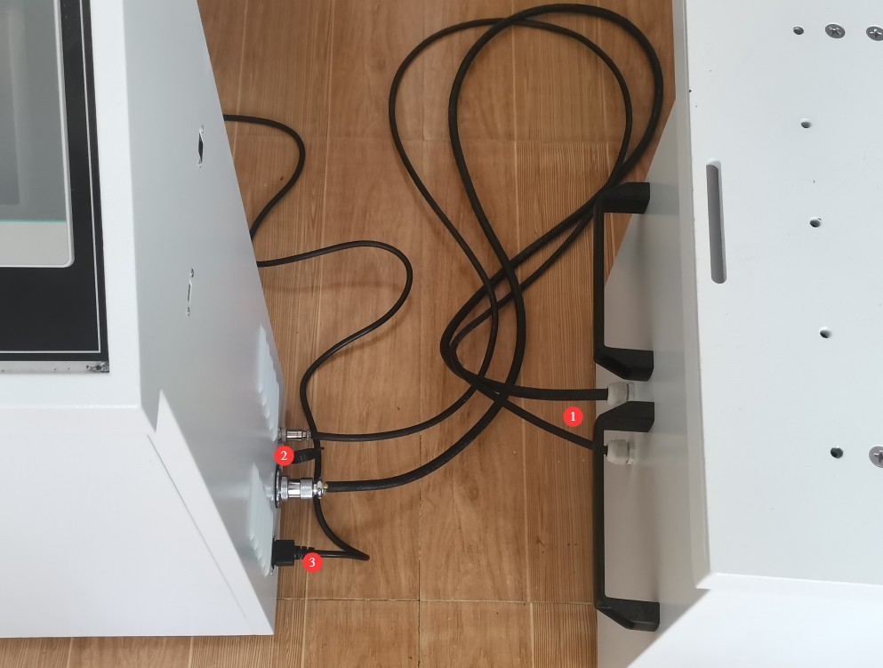
Gambar-3 3
4. Persiapan
4.1 Fiksasi Sampel
Secure the specimen as described in Section 3.2.1 and mount it as closely as possible to the vibration table to ensure that no relative displacement occurs between the specimen and the vibration table during the test.
4.2 Introduction to Handheld Vibration Meters
4.2.1 The Function of a Vibration Meter
Since different samples have different weights and centers of gravity, the amplitude and acceleration will vary even when the same vibration intensity is used. Therefore, the test program cannot directly set the amplitude and acceleration; instead, the required vibration intensity must be adjusted using a vibration meter based on the specific sample and known amplitude or acceleration values.
4.2.2 Assembly of the Vibration Meter
Lihat Gambar 4-1.
| Jumlah | Note |
| ① | Meteran Getaran |
| ② | Connect the vibration meter and the magnet using a signal cable. |
| ③ | magnet |
| ④ | Remove the broken magnetic strip from the magnet |
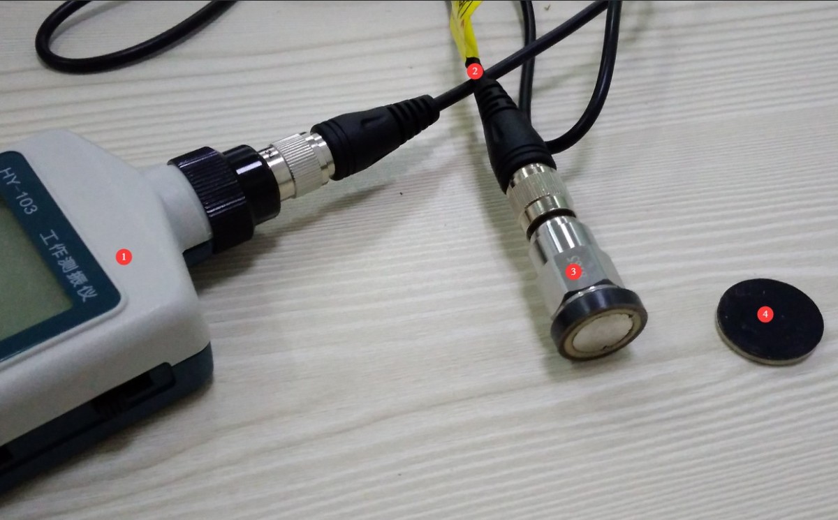
Gambar-4 1
5. Pengujian Getaran
5.1 Pengantar Program Layar Sentuh
After turning on the device, tap the touchscreen to access the initial screen, then tap “Mode Selection,” as shown in Figure 5-1.
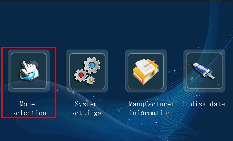
Gambar-5 1
Access the test mode selection screen (see Figure 5-2). Click the desired test mode to enter the parameter settings and test screen.
| Jumlah | Note |
| ① | Vertical Fixed Frequency |
| ② | Vertical Sweep |
| ③ | Horizontal Fixed Frequency |
| ④ | Sapuan Horizontal |
| ⑤ | Vertical Fixed Frequency |
| ⑥ | Vertical Sweep |
| ⑦ | Programmable Fixed Frequency |
| ⑧ | Programmable Sweep |
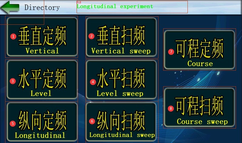
Gambar-5 2
Note: “Vertical” refers to vibration in the vertical direction; “horizontal” refers to vibration in the horizontal direction; and “longitudinal” refers to vibration in the longitudinal direction.
5.2 Fixed-Frequency Vibration Testing
5.2.1 Introduction to the User Interface
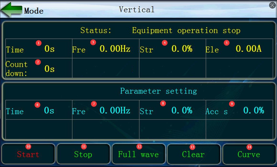
The interfaces and operations for vertical fixed-frequency, horizontal fixed-frequency, and longitudinal fixed-frequency are identical. Taking vertical fixed-frequency as an example, click to enter the vertical fixed-frequency interface, as shown in Figure 5-3.
| Jumlah | Note |
| ① | Displays the duration of the test so far, in seconds |
| ② | Displays the remaining test time in seconds |
| ③ | Displays the current vibration frequency in Hz |
| ④ | Displays the current vibration intensity, in percent |
| ⑤ | Current: Displays the current operating status of the device, in amperes (A) |
| ⑥ | Set the test duration, in seconds |
| ⑦ | Set the vibration frequency in Hz |
| ⑧ | Set the vibration intensity, in % |
| ⑨ | Acceleration slope, in percent. For fixed-value testing, the default acceleration slope is 2%; no modification is necessary. |
| ⑩ | Click to start the test |
| ⑪ | Click to stop the test |
| 1 | Click to toggle between full-wave and half-wave |
| ⑬ | Click to clear test data |
| ⑭ | Click to view the test curve |
Gambar-5 3
5.2.2 Vibration Intensity Calibration
Attach the vibration meter’s magnet to a surface parallel to the direction of vibration. For vertical vibration, attach it directly above the vibration source. For horizontal vibration, attach it to a side parallel to the direction of vibration. Turn on the vibration meter and set it to the displacement mode (in mm) to measure the amplitude of the vibration table; alternatively, set it to the acceleration mode (in m/s²) to measure the vibration acceleration of the vibration table.
Note: Vibration test standards require either amplitude or vibration acceleration, but not both.
On the console’s touchscreen interface, you can first enter a longer test duration, then enter the desired vibration frequency, and start the test after entering a lower vibration intensity—for example, 10%.
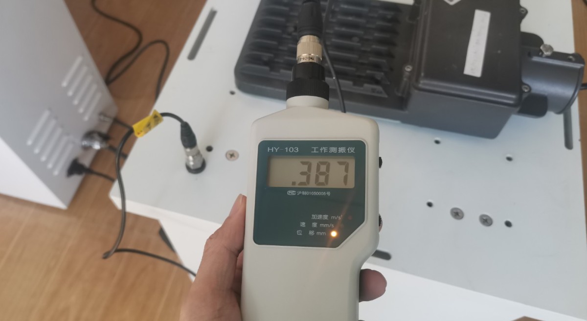
Once the current vibration intensity reaches the set value, check the amplitude and vibration acceleration displayed on the vibration meter, as shown in Figure 5-4.
Gambar-5 4
Then, based on the difference between the measured values and the standard requirements, adjust the vibration intensity until the standard requirements are met.
Note: For the same frequency and vibration intensity, the amplitude and acceleration produced in the three vibration directions are not the same. To facilitate testing, the orientation of the sample may be adjusted as needed.
5.2.3 Uji Startup
Once you have determined the required vibration intensity, re-enter the desired test duration and vibration intensity, and then click “Start” to begin the actual test.
5.3 Sweep Vibration Testing
5.3.1 Introduction to the User Interface
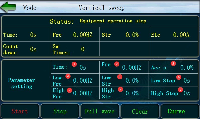
The interface and operation for vertical sweep, horizontal sweep, and longitudinal sweep are the same. Taking the vertical sweep as an example, click to enter the vertical sweep interface, as shown in Figure 5-5.
| Jumlah | Note |
| ① | Set the total test duration |
| ② | Set the frequency slope (e.g., if the high-frequency value is 20 Hz and the low-frequency value is 10 Hz, and the sweep must be completed within 5 seconds, then the frequency slope = (20 Hz – 10 Hz) / 5 s = 2 Hz/s) |
| ③ | Set the acceleration slope (e.g., if the high-frequency vibration intensity is 20% and the low-frequency vibration intensity is 10%, and the sweep must be completed within 5 seconds, then the acceleration slope = (20% – 10%) / 5 seconds = 2%/s) |
| ④ | Set the low-frequency test frequency |
| ⑤ | Set the low-frequency test vibration intensity |
| ⑥ | Set the low-frequency test duration |
| ⑦ | Set the high-frequency test frequency |
| ⑧ | Set the high-frequency test vibration intensity |
| ⑨ | Set the duration of the high-frequency test |
Gambar-5 5
Note: Changes in vibration intensity may not be linear. For example, when conducting a sweep test from 10 Hz to 55 Hz at an amplitude of 0.35 mm, to avoid anomalies during the test, the 10 Hz to 55 Hz range can be divided into multiple segments.using the method described in Section 5.2.2 to record the vibration intensity required for each frequency point to reach an amplitude of 0.35 mm. The frequency range should then be divided into multiple segments, and a programmable sweep test should be conducted in accordance with Section 5.5.
5.3.2 Uji Startup
Once all parameters are set, simply click “Start” to begin the official test.
The vibration test stand first enters the low-frequency test. Once the low-frequency test duration has elapsed, it performs a frequency sweep to the high-frequency test according to the set frequency ramp and vibration intensity ramp; Once the high-frequency test duration has elapsed, the system performs a frequency sweep back to the low-frequency test range according to the preset frequency and vibration intensity ramp rates; this process continues until the total test duration reaches the preset value.
5.4 Programmable Fixed-Frequency Vibration Testing
5.4.1 Introduction to the User Interface
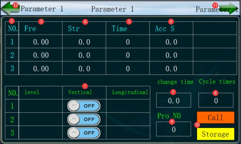
To access the programmable fixed-frequency settings interface, refer to Figure 5-5 for the parameters to be configured.
| Jumlah | Note |
| ① | Vertical orientation only is supported. Please mount the sample in the vertical direction on the vibration test stand. Switch the corresponding segment from “OFF” to “ON.” |
| ② | Paragraph Number |
| ③ | Set a different vibration frequency for each section |
| ④ | Set a different vibration intensity for each segment |
| ⑤ | Set a different test duration for each section |
| ⑥ | Acceleration slope: Use the default value of 2%; no modification is necessary. |
| ⑦ | Time interval between two consecutive test segments |
| ⑧ | Jumlah siklus |
| ⑨ | Nomor Program |
| ⑩ | Save the program, or call the program |
| ⑪ | Click the right arrow to edit paragraphs 4, 5, and 5. |
| 1 | Click the left arrow to enter the test interface. |
Gambar 5–6
5.4.2 Uji Startup
Once all parameters are set, simply click “Start” to begin the official test.
The vibration test stand first enters Test Segment 1. Once the test duration reaches the set interval, it proceeds to Test Segment 2. After completing all test segments, one cycle is completed; this process continues until all cycle tests are completed according to the set number of cycles.
5.5 Programmable Sweep Vibration Testing
5.5.1 Introduction to the User Interface
To access the programmable sweep settings interface, refer to Figure 5-7 for the parameters to be configured.
| Jumlah | Note |
| ① | Vertical orientation only is supported. Please mount the sample in the vertical direction relative to the vibration table for testing. Switch the corresponding segment from OFF to ON. |
| ② | Segment number. The following parameters must be set in order for this segment: low-frequency vibration frequency, low-frequency vibration intensity, high-frequency vibration frequency, high-frequency vibration intensity, sweep test duration, frequency ramp rate, acceleration ramp rate, low-frequency test duration, and high-frequency test duration. |
| ③ | Time interval between two consecutive test segments |
| ④ | Jumlah pengulangan |
| ⑤ | Nomor Program |
| ⑥ | Saving and Loading Programs |
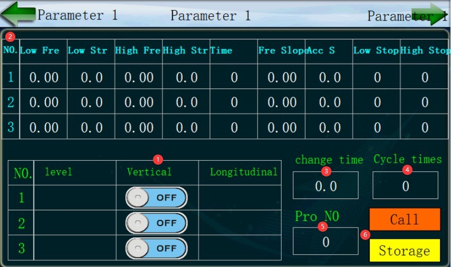
Gambar-5 7
5.5.2 Uji Startup
Once all parameters are set, simply click “Start” to begin the official test.
The vibration table first enters the first segment of the low-frequency test. Once the low-frequency test duration ends, it performs a frequency sweep up to the high-frequency test according to the set frequency slope and vibration intensity slope. Once the high-frequency test period ends, the system proceeds to the second low-frequency test segment, continuing in this manner until all segments of the sweep test are completed, thus finishing one cycle. All cycle tests are completed according to the set number of cycles.
5.6 Akhir Pengujian
5.6.1 Stopping the Test
If an anomaly occurs during the test, please stop the test immediately, troubleshoot the issue, and then restart the test;
If everything goes smoothly during the test, wait for the test to complete normally.
5.6.2 Inspecting Samples
After the test is complete, inspect the sample’s mechanical and electrical performance to determine whether it has passed the test.
6. Pemeliharaan dan Perawatan Peralatan Harian
6.1 Pemeliharaan Harian
Check that the work surface, control panel, and cables are free of damage, oil stains, and loose connections;
Wipe down the countertop and touchscreen, and remove any debris;
Check the screws securing the vibration table and make sure none are loose;
The tabletop operates smoothly, with no unusual noises or jamming.
6.2 Spesifikasi Penyimpanan
6.2.1 Persyaratan Lingkungan Penyimpanan
Suhu: 10°C hingga 35°C; kelembapan relatif: ≤80% RH; lingkungan kering, bebas debu, dan bebas dari gas korosif.
6.2.2 Operasi Penyimpanan Jangka Panjang
Turn off the power and unplug all cables; clean the equipment and wrap it in dust-proof film; power on the vibration test stand for 10 minutes each month to prevent moisture damage to the components.
6.3 Persyaratan Interval Kalibrasi
Untuk memastikan akurasi pengukuran dan keandalan operasional peralatan, disarankan agar peralatan tersebut secara berkala dikirim ke laboratorium metrologi pihak ketiga yang berkualifikasi untuk kalibrasi. Interval kalibrasi yang disarankan adalah 12 bulan. Pengguna dapat menentukan interval kalibrasi spesifik berdasarkan frekuensi penggunaan, kondisi lingkungan, dan persyaratan sistem mutu.
7. Pemecahan Masalah dan Penyelesaian Masalah Umum
| Gejala Kesalahan | Kemungkinan penyebab | Prosedur |
| The sample amplitude is significantly too large. | The sample is not secured, and its center of gravity is too far from the vibration table | Refer to Sections 4.1 and 3.2.1. Secure the specimen to the vibration table and ensure that no relative displacement occurs between the specimen and the vibration table during the test. Secure the specimen as closely as possible to the vibration table so that its center of gravity is near the table surface. |
| Touchscreen Overload Protection Alert | Sample overweight; vibration table operating beyond capacity | Please stop the test, replace the sample with a lighter one, and try again. |