
 Inggris
 中文简体
中文简体 Русский
 Español
 Português
 Türkçe
 العربية
 Deutsch
 Polski
 Italiano
 Français
 한국어
한국어 ไทย
ไทย Tiếng Việt
 日本語
日本語





























Catu Daya AC Tipe PWM (Tiga Fase)
Pengguna manual
berlaku LISUN models: LSP-120KVAST、LSP-120KVASUST、LSP-150KVAST、LSP-150KVASUST、LSP-15KVAST、LSP-15KVASUST、LSP-180KVAST、LSP-180KVASUST、LSP-30KVAST、LSP-30KVASUST、LSP-45KVAST、LSP-60KVAST、LSP-60KVASUST、LSP-90KVAST、LSP-90KVASUST
1. Pemahaman Dasar tentang Peralatan
1.1 Spesifikasi Teknis Utama
| Spesifikasi/Nomor Model | LSP-15KVAST, LSP-30KVAST, …… LSP-180KVAST |
| Kapasitas | 15 kVA, 30 kVA, … 180 kVA |
| Konfigurasi Sirkuit | (IGBT) Sine-Wave Pulse-Width Modulation (SPWM) |
| Tegangan Output | Standard three-phase (can be set to single-phase output), automatic mode; low range: 0–150 V; high range: 150.1–300 V |
| Keluaran Sekarang | LSP-15KVAST: Low range 27A, high range 13.5A. Other models follow the same pattern. |
| Frekuensi Output | 45.00–70.00 Hz |
| Distorsi Bentuk Gelombang | ≤1% (high/low voltage: 220 V/110 V ±15%, resistive load) |
1.2 Verifikasi Konfigurasi Peralatan
1.2.1 Membuka Kemasan dan Pemeriksaan Visual
Saat membuka kemasan perangkat, tangani dengan hati-hati untuk menghindari goresan pada casing dengan alat tajam. Setelah membuka kemasan, periksa terlebih dahulu bagian luar perangkat untuk memastikan tidak ada deformasi atau penyok yang terlihat, dan tombol-tombolnya tidak rusak atau longgar. Jika Anda melihat kelainan pada perangkat atau aksesorinya, jangan menyalakannya. Segera hubungi kami.
1.2.2 Unit Utama dan Aksesoris
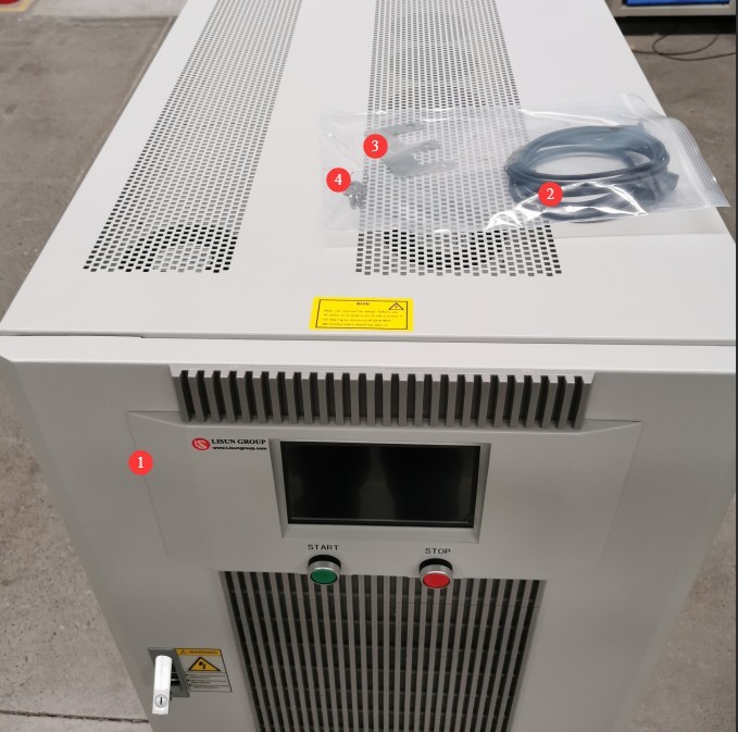
Lihat Gambar 1-1.
| Jumlah | Note |
| ① | LSP-VAST Series Power Supply Unit |
| ② | RS-232 communication cable; the communication function is currently disabled on this device, and this cable is a spare part. |
| ③ | Parallel copper busbars; for instructions on use, see 3.2.2 |
| ④ | Key, used to lock/unlock the front panel of the device |
Gambar-1 1
1.2.3 Mengunduh Dokumen Elektronik
We have already sent download links for the electronic user manual, calibration certificate, warranty card, and other documents via email at the time of shipment. Please download them as soon as possible. If you missed the email, you may contact us to request the download links again.
2. Tindakan Pencegahan Keamanan
2.1 Standar Keselamatan Listrik
Please connect the input power supply strictly in accordance with the specifications on the equipment nameplate. The equipment must be properly grounded, with a protective grounding resistance of ≤4 Ω, to prevent the risk of electric shock.
2.2 Standar Keselamatan Lingkungan
For indoor use only; avoid direct sunlight. Place on a sturdy, stable surface to prevent severe vibrations. Ensure the environment is free of dust, corrosive gases, and flammable or explosive materials. Keep away from strong magnetic and electric fields. Ensure adequate ventilation; leave at least 10 cm of space around the device for heat dissipation, and do not block the cooling fan vents. Operating Environment: Temperature 5°C to 35°C, relative humidity ≤65%.
2.3 Pedoman Keselamatan Operasional
Do not operate the equipment or plug in or unplug the power cord with wet hands; Output must be turned off before connecting or disconnecting wires; do not touch the output terminals, internal components, the load, or the load wiring while the equipment is operating; do not shut down the equipment directly while it is in the output state; turn off the output first before shutting down the equipment; if you notice a strange odor, smoke, unusual noise, or overheating, immediately disconnect the power and do not continue operation.
3. Gambaran Umum Peralatan dan Pengkabelan
3.1 Equipment Appearance
3.1.1 Pengantar Panel Depan
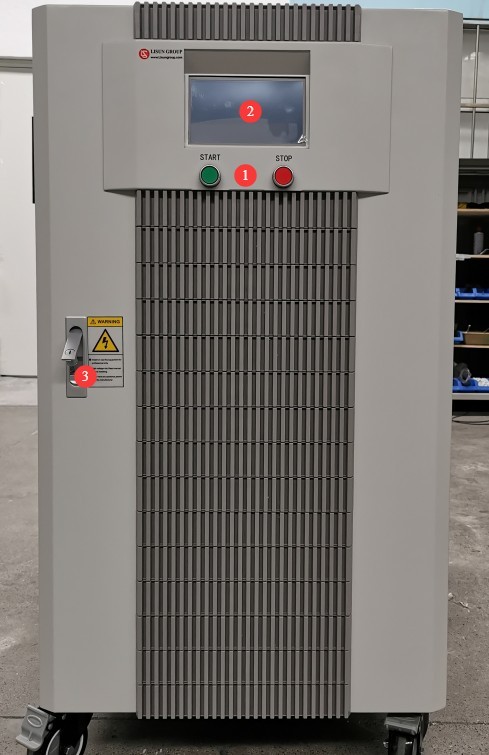
Lihat Gambar 3-1.
| Jumlah | Note |
| ① | On/Off Output Button |
| ② | Touchscreen |
| ③ | Front panel; open it to reveal the input and output wiring panel |
Gambar-3 1
3.1.2 Product Nameplate Information
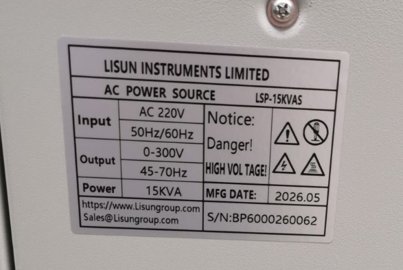
See Figure 3-2. The input and output voltages listed on the nameplate are line voltages (voltages between phases); please use these values as a guide when wiring the unit.
Gambar-3 2
3.2 Pengkabelan Peralatan
3.2.1 Standard Wiring
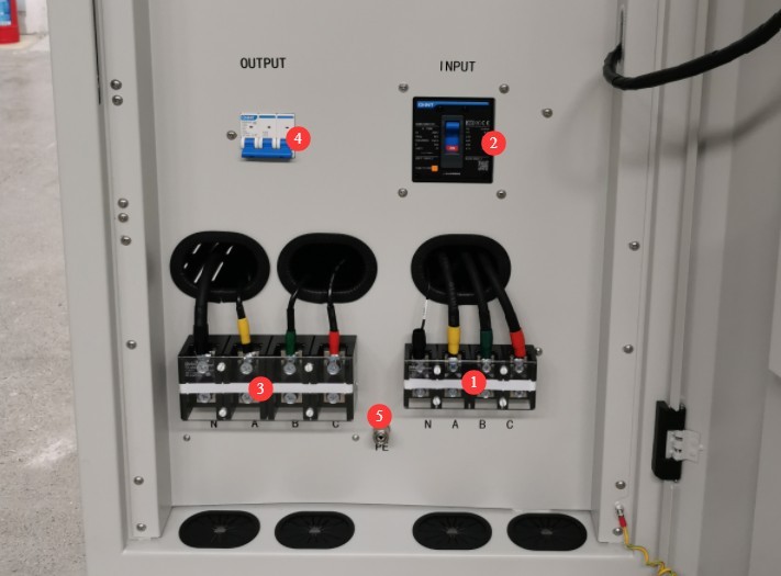
Lihat Gambar 3-3.
| Jumlah | Note |
| ① | Input wire terminals, consisting of three live wires and one neutral wire |
| ② | Input Switch |
| ③ | Output wire terminals, consisting of three live wires and one neutral wire |
| ④ | Sakelar Output |
| ⑤ | Equipment Grounding Terminal |
Gambar-3 3
3.2.2 Parallel Single-Phase Wiring
To drive a high-power single-phase load, use the single-phase parallel function (see Section 4.3) and short-circuit the three output live wires using a parallel copper busbar.
The remaining wiring is the same as in Section 3.2.1.
4. Pengantar Program Layar Sentuh
4.1 Layar Awal
After confirming that the wiring is correct, turn on all input and output switches. The touchscreen will light up and display the initial screen, which shows the standard three-phase output mode. See Figure 4-1.
| Jumlah | Note |
| ① | Gear indicators: “H” indicates high gear; no indicator means low gear. |
| ② | Output status display: “OFF” indicates no output; “ON” indicates output |
| ③ | Output Voltage Settings: The default setting is phase voltage (L-N), which can be switched to line voltage (L-L) on the system interface. |
| ④ | Output Frequency Settings |
| ⑤ | Output voltage display: By default, phase voltage (L-N) is displayed; this can be switched to line voltage (L-L) on the system interface. |
| ⑥ | Output Current Display |
| ⑦ | Output Frequency Display |
| ⑧ | Antarmuka Sistem |
| ⑨ | Output Types and Operating Modes |
| ⑩ | Quick Setup: Opens the Quick Setup screen, allowing you to quickly set the desired voltage and frequency. |
| ⑪ | On the next page, you can view reactive power, active power, and power factor. |
| 1 | Start/Stop Output Button—functions the same as the Start/Stop Output button on the front panel |
| ⑬ | The touchscreen can be locked or unlocked; it automatically locks after a period of inactivity. |
| ⑭ | When the touchscreen is locked, a lock icon appears here. |
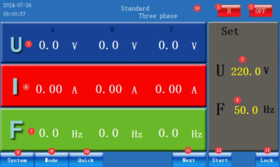
Gambar-4 1
4.2 System Interface
Lihat Gambar 4-2.
| Jumlah | Note |
| ① | Gear Selection: Low, High, or Auto |
| ② | Beralih antara Bahasa Mandarin dan Bahasa Inggris |
| ③ | L-L/L-N Display Switching |
| ④ | Kembali ke Layar Beranda |
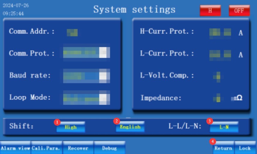
Gambar-4 2
Note: Leave the other settings on this screen at their factory defaults; do not change them.
4.3 Output Type and Operating Mode Interface
See Figure 4-3. The left column lists the output type options, and the right column lists the operating mode options.
| Jumlah | Note |
| ① | Keluaran tiga fase |
| ② | Single-phase parallel connection: Use copper busbars to short-circuit the three output phases to connect high-power single-phase loads. |
| ③ | American Standard two-phase, using N/A/B terminals |
| ④ | The three phases are independent; you can set parameters for each phase separately and control whether each phase outputs power individually, allowing you to connect three different single-phase loads. |
| ⑤ | Three-phase imbalance: Three-phase voltage parameters and phase angles can be set individually; the phase angle range for phases A and B is 110°–130°, the phase angle range for phases A and C is 230°–250°, and the phase angle for phases B and C is automatically matched. |
| ⑥ | Standard mode: All three phases are 120° apart, and the same voltage and frequency are set for all three phases. |
| ⑦ | Step mode: Allows programmable settings for different output voltages, frequencies, and output durations; automatically switches after output. |
| ⑧ | Gradual transition mode: The start and end values for output voltage and frequency, as well as the transition duration, can be programmed; after the output is activated, the voltage and frequency change gradually and uniformly. |
| ⑨ | Harmonic Mode: 30 harmonic types to choose from; fundamental voltage and fundamental frequency can be set |
| ⑩ | Soft-start mode: You can set the start voltage, start frequency, and start time simultaneously. |
| ⑪ | Step Mode: Allows you to set the initial output voltage and frequency, as well as the step voltage, step frequency, and step time. After output begins, the system automatically steps up or down from the initial voltage and frequency. |
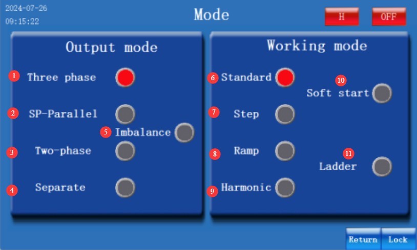
Gambar-4 3
Note 1: The default output type for this equipment is three-phase, and the default operating mode is Standard Mode.
Note 2: The available operating modes vary by output type; please follow the prompts on the device interface to make your selection.
Note 3: The available settings vary by output type; please follow the prompts on the device interface to make your selection.
5. Pemeliharaan dan Perawatan Peralatan Harian
5.1 Perawatan Rutin
5.1.1 Pembersihan Harian
Be sure to turn off the power and unplug the power cord before cleaning. We recommend using a soft, anti-static cotton cloth and a neutral detergent to wipe down the unit. Never spray liquid directly onto the device to prevent liquid from entering the interior.
5.1.2 Pemeriksaan Rutin
Before each use, check to ensure that the power cord and terminal connections are secure and free of burn marks; that the fan vents are not blocked; and, after turning on the unit, verify that the display is functioning properly.
5.2 Spesifikasi Penyimpanan
5.2.1 Persyaratan Lingkungan Penyimpanan
Suhu: 5°C hingga 35°C; kelembapan relatif: ≤65% RH; lingkungan kering, bebas debu, dan bebas dari gas korosif.
5.2.2 Operasi Penyimpanan Jangka Panjang
Turn off the power and unplug all cables; clean the equipment and wrap it in dust-proof film; power it on for 30 minutes each month to prevent moisture damage to the components.
5.3 Persyaratan Interval Kalibrasi
Untuk memastikan akurasi pengukuran dan keandalan operasional peralatan, disarankan agar peralatan tersebut secara berkala dikirim ke laboratorium metrologi pihak ketiga yang berkualifikasi untuk kalibrasi. Interval kalibrasi yang disarankan adalah 12 bulan. Pengguna dapat menentukan interval kalibrasi spesifik berdasarkan frekuensi penggunaan, kondisi lingkungan, dan persyaratan sistem mutu.
6. Pemecahan Masalah dan Penyelesaian Masalah Umum
| Gejala Kesalahan | Kemungkinan penyebab | Prosedur |
| Alarm values “11/21/31” | IGBT Module Protection | Check for short circuits; try again after ruling them out. |
| Alarm values “12/22/32” | Arus lebih | Reduce the load or check for a short circuit |
| Alarm values “13/23/33” | Overload | Reduce the load or purchase a power supply with a higher capacity |
| Alarm thresholds “14/24/34” | Overheating | This may be caused by excessive ambient temperature, excessive load, or a fan shutdown; address each issue accordingly. |
| Alarm thresholds “15/25/35” | Tegangan lebih | Check whether there are any abnormalities in the actual output voltage and the displayed voltage. |
| The computer won’t turn on or there is no display | Input power supply abnormal | Check whether the input power supply is normal and whether there are any wiring errors or loose connections. |
| Power supply output fluctuations exceed the permissible range | Insufficient power supply warm-up, abnormal Input power supply; abnormal load | After powering on and allowing the system to warm up for five minutes, operate it under load; check that the input power supply is within the normal permissible range; check that the load is operating normally. |