
 Inggris
 中文简体
中文简体 Русский
 Español
 Português
 Türkçe
 العربية
 Deutsch
 Polski
 Italiano
 Français
 한국어
한국어 ไทย
ไทย Tiếng Việt
 日本語
日本語





























Penganalisis Harmonik dan Kedipan
Pengguna manual
berlaku LISUN models: LSAIF-503、LSHF61000-3-2/3
1. Pemahaman Dasar tentang Peralatan
1.1 Konfigurasi Sistem
The Harmonics and Flicker Analyzer is a complete, certification-grade single-phase electromagnetic compatibility (EMC) test system consisting of three professionally matched instruments.
| Jumlah | Note |
| ①LSHF61000-3-2/3 Harmonic and Flicker Analyzer | Core measurement unit responsible for collecting power quality parameters, performing harmonic analysis, and calculating flicker |
| ②LSAIF-503 Scintillation Impedance Network | Simulates the grid impedance characteristics specified in the standard to ensure the accuracy of the flicker test results |
| ③LSP-*VAC-HF Low-Distortion AC Power Supply | Provides a clean, stable sinusoidal voltage to the equipment under test (EUT), eliminating harmonic and ripple interference from the power grid itself |
1.2 Prinsip Operasi
System acquires the input signals from the device under test via voltage and current pure-resistance sampling sensors. After high-fidelity amplification and 16-bit high-speed analog-to-digital conversion, the signals are processed in real time by the digital processing module.
| uji Produk | Note |
| Pengujian Harmonik | Performs precise analysis of 2nd through 50th harmonic components, automatically compares results against the limit values specified in the GB 17625.1 (IEC 61000-3-2) standard, supports harmonic limit evaluations for Class A, B, C, and D equipment, and automatically generates pass/fail determinations. |
| Uji Kedipan | Complies with the GB 17625.2 (IEC 61000-3-3) standard, and calculates short-term flicker value (Pst), long-term flicker value (Plt), and parameters such as dt, dc, dmax, and Tmax by simulating the human eye’s perception of voltage fluctuations |
| Input Characteristic Testing | Measure basic power quality parameters such as voltage, current, power, and power factor |
1.3 Verifikasi Konfigurasi Peralatan
1.3.1 Membongkar
Saat membuka kemasan perangkat, tangani dengan hati-hati untuk menghindari goresan pada casing dengan alat tajam. Setelah membuka kemasan, periksa terlebih dahulu bagian luar perangkat untuk memastikan tidak ada deformasi atau penyok yang terlihat, dan tombol-tombolnya tidak rusak atau longgar. Jika Anda melihat kelainan pada perangkat atau aksesorinya, jangan menyalakannya. Segera hubungi kami.
1.3.2 Unit Utama dan Aksesoris
Main units: One each of the LSHF61000-3-2/3, LSAIF-503, and LSP-*VAC-HF.
See Figure 1-1 for the main components.
| Jumlah | Note |
| ① | Power connection cable, used to connect the LSAIF-503 and the LSHF61000-3-2/3 |
| ② | USB cable for connecting the LSHF61000-3-2/3 to a computer |
| ③ | RS-232 communication cable/RS-232-to-USB adapter cable, used to connect the LSP-*VAC-HF to a computer |
| ④ | EUT power cord, used to connect the LSHF61000-3-2/3 to the EUT |
| ⑤ | Kabel Listrik |
| ⑥ | Sekering cadangan |
| ⑦ | Power Adapter for the LSAIF-503 |
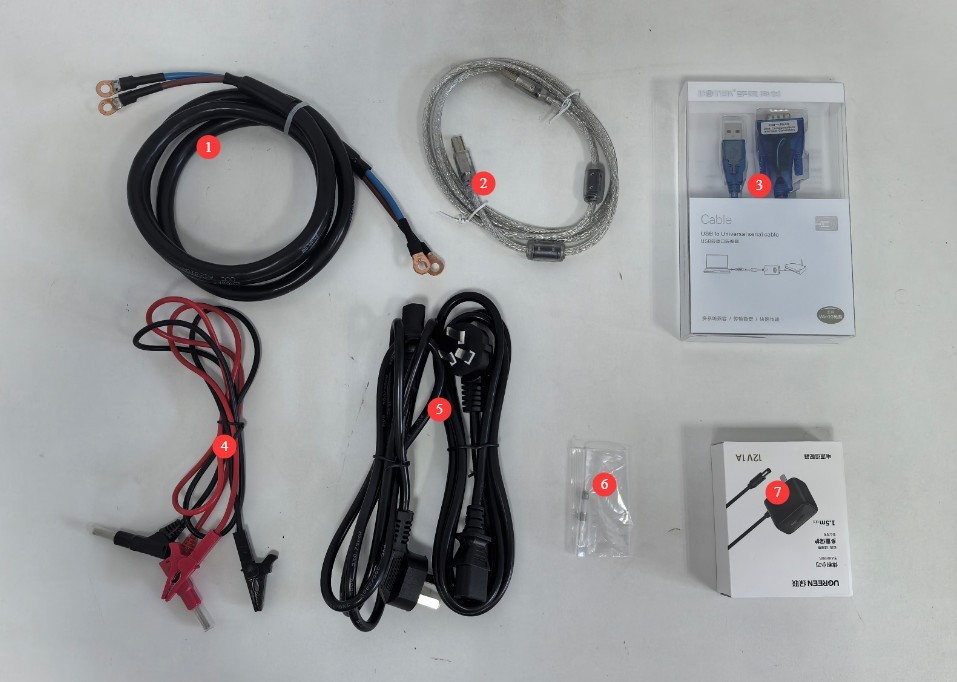
Gambar-1 1
1.3.3 Mengunduh Dokumen Elektronik
Kami telah mengirimkan tautan unduhan untuk manual pengguna elektronik, sertifikat kalibrasi, kartu garansi, dan dokumen lainnya melalui email pada saat pengiriman. Mohon segera unduh. Jika Anda belum menerima email tersebut, silakan hubungi kami untuk meminta tautan unduhan lagi.
2. Tindakan Pencegahan untuk Penggunaan
2.1 Keamanan Listrik
System must be connected to a stable single-phase AC 220V ±10%, 50/60 Hz power source, and ensure proper grounding with a ground resistance of ≤1 Ω;
Do not use the equipment if the power connections are loose or the cables are damaged.
2.2 Keselamatan Lingkungan
The equipment must be placed in a dry, well-ventilated environment free of dust and corrosive gases, away from flammable and explosive materials;
Suhu lingkungan: 15–35°C; kelembapan relatif: ≤65% (tanpa kondensasi);
Jauhkan peralatan dari medan magnet yang kuat dan medan listrik yang kuat.
2.3 Keselamatan Operasional
High-Voltage Hazard: High voltage is present inside the instrument; under no circumstances should the housing be opened while the power is on;
Wiring Safety: Before connecting or disconnecting the EUT, the LSP-*VAC-HF power output must be turned off;
Secure Wiring: Ensure that all terminal connections are reliable and secure to prevent poor contact or sparks caused by loose connections;
Troubleshooting: If you notice that the instrument emits an unusual odor, smoke, or makes unusual noises, immediately disconnect all power sources and contact the manufacturer for repairs;
No Modifications: Do not modify the instrument or replace any internal components without the manufacturer’s written consent.
2.4 Lainnya
Untuk hal-hal yang tidak tercakup dalam panduan ini, harap berhati-hati atau hubungi kami.
3. Gambaran Umum Peralatan dan Pengkabelan
3.1 LSHF61000-3-2/3 Instrument Panel Description
3.1.1 Panel Depan
Lihat Gambar 3-1.
| Jumlah | Note |
| ① | Load button: Turns the EUT power on or off |
| ② | Touchscreen that displays test parameters and results. Note: When using the computer software, there is no need to operate the touchscreen. |
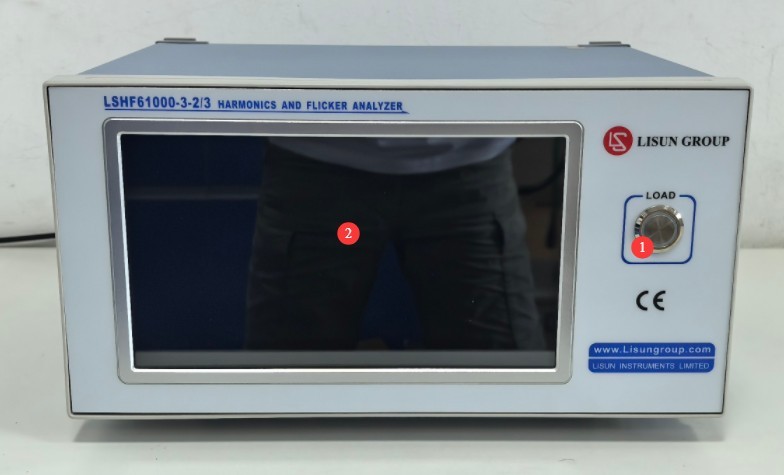
Gambar-3 1
3.1.2 Panel Belakang
Lihat Gambar 3-2.
| Jumlah | Note |
| ① | Saklar daya |
| ② | Power Cord Jack and Fuse |
| ③ | Output terminals, connected to the EUT |
| ④ | Input terminal, connected to the output terminal on the front panel of the LSAIF-503 |
| ⑤ | USB port, for connecting to a computer |
| ⑥ | RS-232 and other ports, for backup |
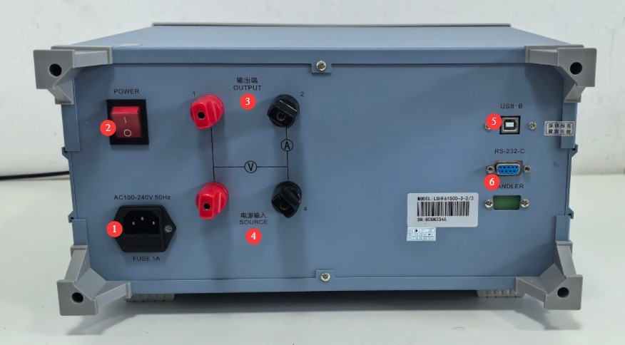
Gambar-3 2
3.2 LSAIF-503 Instrument Panel Description
3.2.1 Panel Depan
Lihat Gambar 3-3.
| Jumlah | Note |
| ① | Output terminal, connected to the input terminal on the back panel of the LSHF61000-3-2/3 |
| ② | To test for flickering, set the switch to “FLICKER”; to test for harmonics, set the switch to “BYPASS.” |
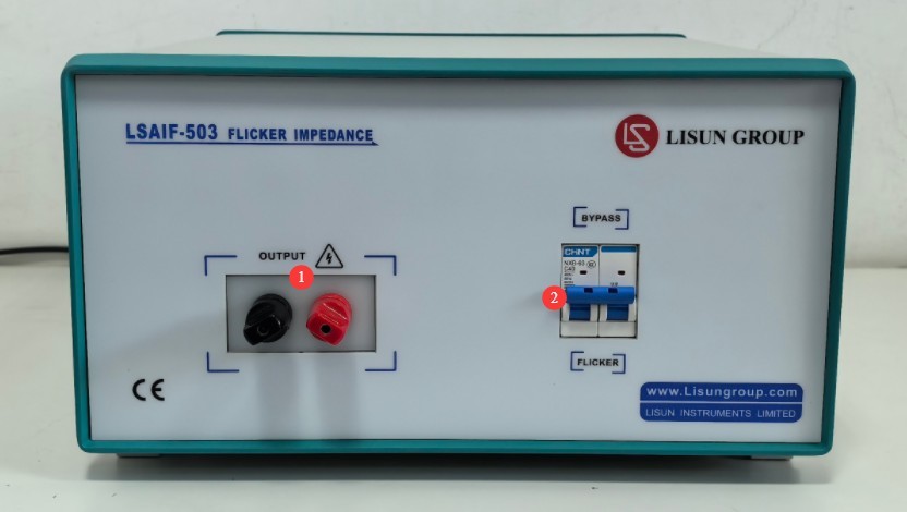
Gambar-3 3
3.2.2 Panel Belakang
Lihat Gambar 3–4.
| Jumlah | Note |
| ① | Power input cable, connected to the LSP-*VAC-HF output port |
| ② | 12V DC power connector for connecting the power adapter |
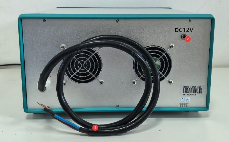
Gambar-3 4
3.3 LSP-*VAC-HF Instrument Panel Description
3.3.1 Panel Depan
Lihat Gambar 3–5.
| Jumlah | Note |
| ① | Saklar daya |
| ② | Display |
| ③ | Control Panel: The LSP-*VAC-HF can be controlled using software; there is no need to use the control panel. |
| ④ | Power Output Button: The LSP-*VAC-HF power output can be controlled via software, eliminating the need for the output button. |
| ⑤ | Output port; connect the input power supply cord to the LSAIF-503 back panel |
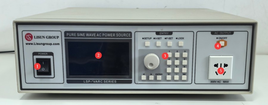
Gambar-3 5
3.3.2 Panel Belakang
Lihat Gambar 3–6.
| Jumlah | Note |
| ① | Power Cord Jack |
| ② | Sekering |
| ③ | Input voltage switching: The device is set to 230V by default at the factory. Please do not change this setting arbitrarily. |
| ④ | RS-232 communication port, connected to a computer via a communication cable |
| ⑤ | Synchronization signal output port—no connection required |
| ⑥ | Power output port—this functions the same as the front-panel output port; simply connect to either one. |
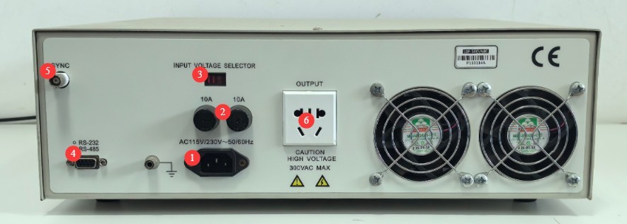
Gambar-3 6
4. Instalasi dan Konfigurasi Perangkat Lunak
4.1 Instalasi Perangkat Lunak dan Driver
4.1.1 Lingkungan Eksekusi Perangkat Lunak
System Requirements: Windows 7/Windows 8/Windows 10/Windows 11 (32-bit/64-bit); the computer must have at least two USB ports.
4.1.2 Instalasi Perangkat Lunak
Lihat Gambar 4-1.
| Jumlah | Note |
| ① | LSHF61000-3-2/3 software—please double-click to install |
| ② | RS232-USB Adapter Driver—Double-click to install |
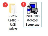
Gambar-4 1
If, during the software installation process, your antivirus software or Windows Firewall flags a file as suspicious, you can add the installer to the trust list in your antivirus software and firewall, or temporarily disable your security software and try the installation again. Once the installation is complete, restore your security protection.
Note: After the software is successfully installed, two icons will appear on the desktop: “LSHF61000-3-2 Harmonic Analyzer” and “LSHF61000-3-3 Flicker Analyzer.” When using the software, only one of these programs may be open at a time; otherwise, communication errors may occur.
4.2 Pengaturan Perangkat Lunak
4.2.1 LSHF61000-3-2 Harmonic Analyzer Software
See Figure 4-2; click to install the driver.
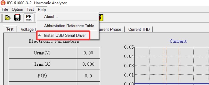
Gambar-4 2
As shown in Figure 4-3, enter the port settings screen.
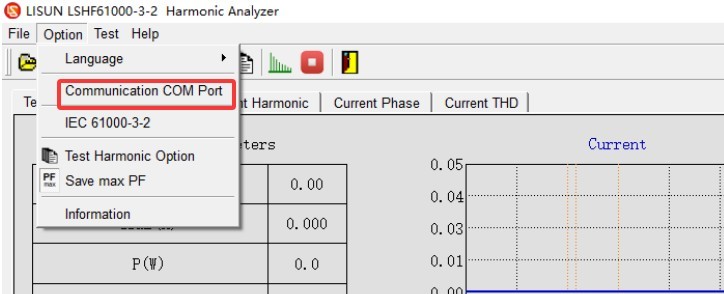
Gambar-4 3
For setup instructions, see Figure 4-4.
| Langkah Penyiapan | Note |
| LSHF61000-3-2/3 Communication | |
| ① | First, manually select any port |
| ② | Ensure the baud rate is 1000,000 |
| ③ | Click “Automatically Search for Ports”; if communication is successful, a message will appear indicating that the search was successful. |
| LSP-*VAC-HF Communication | |
| ④ | Check the “Power Options” box |
| ⑤ | First, manually select any port. |
| ⑥ | Ensure the baud rate is 9600 |
| ⑦ | Select model LSP-*VAC-HF |
| ⑧ | Click to automatically search for the port; if communication is successful, a message will appear indicating that the search was successful. |
| ⑨ | After the search for all ports is complete, click OK to save and exit. |
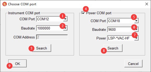
Gambar-4 4
4.2.2 LSHF61000-3-3 Flicker Analyzer Software
See Figures 4–5; click to install the driver.
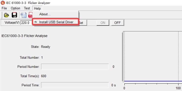
Gambar 4–5
See Figures 4–6 to access the port settings screen.
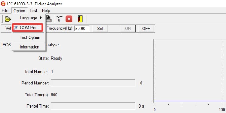
Gambar 4–6
For setup instructions, see Figures 4–7.
| Langkah Penyiapan | Note |
| LSHF61000-3-2/3 Communication | |
| ① | First, manually select any port. |
| ② | Ensure the baud rate is 1000,000 |
| ③ | Click “Automatically Search for Port.” If communication is normal, a message will appear indicating that the search was successful. |
| LSP-*VAC-HF Communication | |
| ④ | Check the “Power Options” box |
| ⑤ | First, manually select any port. |
| ⑥ | Ensure the baud rate is 9600 |
| ⑦ | Select model LSP-*VAC-HF |
| ⑧ | Click “Automatically Search for Ports.” If communication is successful, a message will appear indicating that the search was successful. |
| ⑨ | After the search for all ports is complete, click OK to save and exit. |
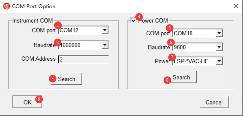
Gambar 4-7
5. GB 17625.1 (IEC 61000-3-2) Harmonic Testing
5.1 Persiapan Instrumen
| Tangga | Note |
| ① | Refer to Chapter 3 to complete all wiring, and turn on all devices. |
| ② | Refer to Section 3.2.1 and set the switch to the BYPASS position. |
| ③ | Refer to Section 3.1.1; press the load button to turn on the power to the EUT. |
5.2 Persiapan Perangkat Lunak
5.2.1 Test Options
Lihat Gambar 5-1.
| Jumlah | Note |
| ① | The software comes preconfigured with the limit values specified in the IEC 61000-3-2 standard and requires no modification. If you have special requirements, you can click to modify the relevant data. |
| ② | Harmonic Test Options |
| ③ | Click to select and save the maximum PF value recorded during the test. |
| ④ | Product and Test Data Entry |
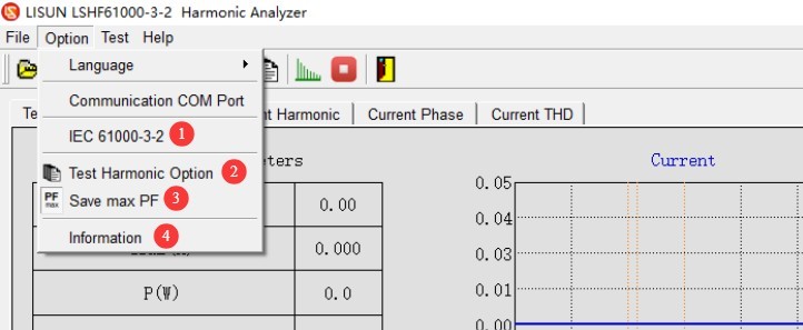
Gambar-5 1
5.2.2 Harmonic Test Options Screen
Lihat Gambar 5-2.
| Jumlah | Note |
| ① | Select the test category to be used as a basis (IEC Class 4 equipment and related categories are pre-installed). Class A: Balanced three-phase equipment, household appliances (excluding Class C and Class D), tools (excluding portable tools), etc.; Class B: Portable tools, non-professional arc welding equipment; Class C: Lighting equipment (including dimmers); Class D: Personal computers, televisions, monitors, etc., with a power rating ≤600 W |
| ② | Set the rated voltage and frequency for the EUT to automatically control the output of the LSP-*VAC-HF power supply. |
| ③ | Set voltage fluctuation limits to automatically control the output of the LSP-*VAC-HF power supply |
| ④ | Click to activate the LSP-*VAC-HF power output, with the EUT in normal operating mode. |
| ⑤ | After the test is complete, click to disconnect the LSP-*VAC-HF power output. |
| ⑥ | All other parameters on this screen have been configured in accordance with the standard. If you have any special requirements, you can click “Add/Edit” to customize the test level name or modify the test parameters. |
| ⑦ | Click to select, then enable the test parameters that have been selected and edited. |
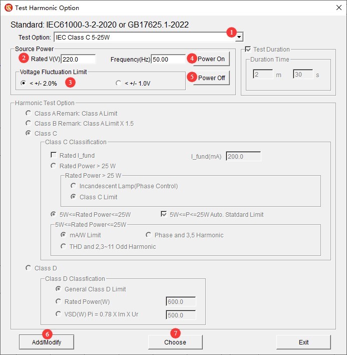
Gambar-5 2
5.3 Pengujian Harmonik
5.3.1 Dimmable Light Pre-test
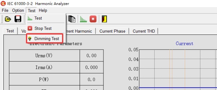
See Figure 5-3; click to access the dimmable light pre-test interface.
Gambar-5 3
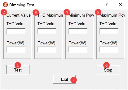
See Figure 5-4 for the procedure.
| Jumlah | Note |
| ① | After clicking “Test,” slowly and steadily adjust the dimmer from the lowest brightness to the highest brightness, then slowly return it to the lowest brightness to complete a full dimming cycle. |
| ② | This column displays the current THC value and power. |
| ③ | This column shows the maximum THC value and its power. |
| ④ | This column shows the minimum power values and their THC values. |
| ⑤ | This column displays the maximum power values and their THC values. |
| ⑥ | After completing the dimming operation, record all the data and click “Stop Test.” |
| ⑦ | Click to log out |
Gambar-5 4
In accordance with the requirements of the reference standard and based on the preliminary test data, access the harmonic test options screen (see 5.2.2) to reconfigure the test parameters.
5.3.2 Run the harmonic test and view the test report
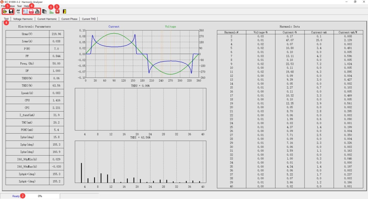
Lihat Gambar 5-5.
| Jumlah | Note |
| ① | Click to Start the Test |
| ② | The test progress is displayed here; the default test duration is 150 seconds. |
| ③ | If any abnormalities occur, you may click to end the test. Note: If the test is terminated, no valid test data will be provided. |
| ④ | After the test is complete, the software interface displays the test results. You can click the tabs to switch between the overall report, voltage harmonics, current harmonics, current phase angle, and total current harmonics. |
| ⑤ | You can save or open the original test file. Note: The original test file can only be opened using LISUN perangkat lunak. |
| ⑥ | Export test reports to Word, export test reports to PDF, print test reports |
Gambar-5 5
5.3.3 Instrument Operation at the End of Testing
| Tangga | Note |
| ① | Refer to Section 5.2.2, navigate to the harmonic test options screen, and click to disable the LSP-*VAC-HF power output. |
| ② | Refer to 3.1.1; press the load button again to cut off power to the EUT. |
| ③ | Replace the EUT for testing, or turn off the instrument |
6. GB 17625.2 (IEC 61000-3-3) Flicker Test
6.1 Persiapan Instrumen
| Tangga | Note |
| ① | Refer to Chapter 3 to complete all wiring, and turn on all equipment. |
| ② | Refer to Section 3.2.1 and set the toggle switch to the “FLICKER” position. |
| ③ | Refer to Section 3.1.1; press the load button to turn on the EUT’s power supply. |
6.2 Persiapan Perangkat Lunak
6.2.1 Settings Options Drop-down List
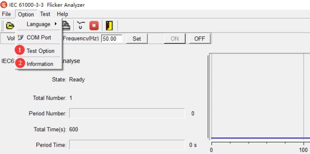
Lihat Gambar 6-1.
| Jumlah | Note |
| ① | Flicker Test Options |
| ② | Product and Test Data Entry |
Gambar-6 1
6.2.2 Flicker Test Options Interface
Lihat Gambar 6-2.
| Jumlah | Note |
| ① | Default test options, already configured according to the standard |
| ② | If you need to make changes, click “Add/Edit” to modify the test option names and their parameters. |
| ③ | Click to select, then enable the test parameters that have been selected and edited. |
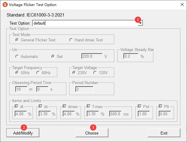
Gambar-6 2
6.3 Flicker Test
6.3.1 Run the test and view the test report
Lihat Gambar 6-3.
| Jumlah | Note |
| ① | Apply the correct voltage and frequency to the EUT |
| ② | Click SET to configure and activate the LSP-*VAC-HF power output, bringing the EUT into normal operating mode. |
| ③ | Click to start the flashing test |
| ④ | The test progress is displayed here. The default test duration is 10 minutes × 2 = 20 minutes. |
| ⑤ | If any abnormalities occur, you may click to end the test. Note: If the test is terminated, no valid test data will be provided. |
| ⑥ | Once the test is complete, you can click to disconnect the LSP-*VAC-HF power output. |
| ⑦ | You can save or open the original test file. Note: The original test file can only be opened using LISUN perangkat lunak. |
| ⑧ | Export test reports as Word files, export test reports as PDF files, print test reports |
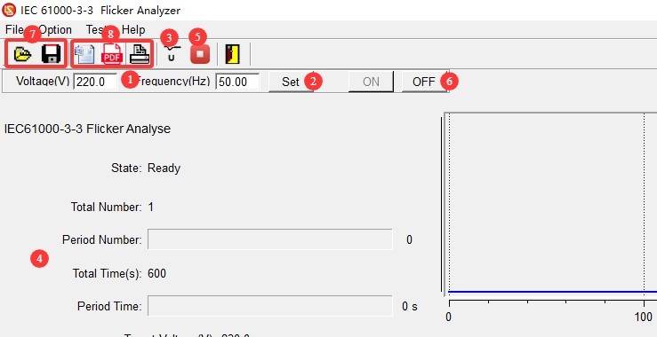
Gambar-6 3
6.3.2 Instrument Operation at the End of the Test
| Tangga | Note |
| ① | Refer to Section 6.3.1 and click to cut off the LSP-*VAC-HF power output. |
| ② | Refer to 3.1.1; press the load button again to cut off power to the EUT. |
| ③ | Replace the EUT for testing, or turn off the instrument |
7. Pemeliharaan dan Perawatan Peralatan Harian
7.1 Pembersihan Harian
Regularly wipe down the instrument housing with a clean, soft cloth to remove dust and stains; when cleaning the touchscreen, gently wipe it with a soft microfiber cloth, and avoid using organic solvents; when cleaning the terminal blocks, wipe them with anhydrous alcohol to remove oxidation and dirt.
7.2 Inspeksi Berkala
Check the power cord and test leads for any damage or signs of wear; check that the terminals are secure and not loose; check that the instrument’s ventilation openings are not blocked.
7.3 Spesifikasi Penyimpanan
7.3.1 Persyaratan Lingkungan Penyimpanan
Suhu: 5°C hingga 35°C; kelembapan relatif: ≤65% RH; lingkungan kering, bebas debu, dan bebas dari gas korosif.
7.3.2 Operasi Penyimpanan Jangka Panjang
Matikan daya dan cabut semua kabel; bersihkan peralatan dan bungkus dengan plastik anti debu; hidupkan daya selama 30 menit setiap bulan untuk mencegah kerusakan akibat kelembapan pada komponen.
7.4 Persyaratan Interval Kalibrasi
Untuk memastikan akurasi pengukuran dan keandalan operasional peralatan, disarankan agar peralatan tersebut secara berkala dikirim ke laboratorium metrologi pihak ketiga yang berkualifikasi untuk kalibrasi. Interval kalibrasi yang disarankan adalah 12 bulan. Pengguna dapat menentukan interval kalibrasi spesifik berdasarkan frekuensi penggunaan, kondisi lingkungan, dan persyaratan sistem mutu.
8. Pemecahan Masalah dan Penyelesaian Masalah Umum
| Gejala Kesalahan | Kemungkinan penyebab | Prosedur |
| Layar sentuh tidak responsif | Dust or smudges on the touchscreen surface, or System freezes | After turning off the instrument, clean the touchscreen surface and restart the instrument. |
| No test data | Terminating the Test During the Testing Process | Do not manually stop the test; wait for it to complete normally. |
| The software won’t start | You did not log in to the computer with an administrator account and run the software. | Please log in to your computer with an administrator account, right-click the software icon, and select “Run as administrator.” |
| Communication and Testing Errors | Both programs are running at the same time | Only one program may be open at a time; close the current program before opening another one. |
| Abnormal Flicker Test Results | Not connected to the LSAIF-503 scintillation impedance network | Connect the LSAIF-503 according to standard procedures, and set the front-panel selector switch to FLICKER. |
| Measurement Accuracy Deviation | The ambient temperature is too high or too low, or the test cable is too long or too thin. | Return the test environment to room temperature, and use the standard test cable or a thicker test cable. |