
 Inggris
 中文简体
中文简体 Русский
 Español
 Português
 Türkçe
 العربية
 Deutsch
 Polski
 Italiano
 Français
 한국어
한국어 ไทย
ไทย Tiếng Việt
 日本語
日本語





























Pendeteksi Bergerak Goniophotometer
Pengguna manual
berlaku LISUN Model: LSG-6000,LSG-6000B.LSG-6000BCCD,LSG-6000CCD,LSG-6000L、LSG-6000LCCD、LSG-6000S、LSG-6000SCCD
1. Membuka Kemasan dan Mengenal Peralatan Secara Dasar
1.1 Membuka Kemasan dan Pemeriksaan
When unpacking the device, handle it gently to avoid scratching the casing with sharp tools. After unpacking, first inspect the exterior of the device to ensure there are no visible deformations or dents, and that the buttons are not damaged or loose. If you notice any abnormalities with the device or its accessories, do not turn it on. Please contact us immediately.
1.2 System Configuration and Overview
1.2.1 Model Classification
| Pilih Model | Kategori Ukuran | Differentiation by Core Features |
| LSG-6000S | Kecil | Includes near-field photometric probes and far-field photometric probes; no Spectroradiometer |
| LSG-6000SCCD | Includes near-field photometric probes and far-field photometric probes; features a Spectroradiometer | |
| LSG-6000 | Model Standar | Includes near-field and far-field photometric probes; no Spectroradiometer |
| LSG-6000CCD | Includes near-field photometric probes and far-field photometric probes; features a Spectroradiometer | |
| LSG-6000B | Skala besar | Includes near-field photometric probes and far-field photometric probes; no Spectroradiometer |
| LSG-6000BCCD | Includes near-field photometric probes and far-field photometric probes; features a Spectroradiometer | |
| LSG-6000L | Sangat besar | Includes near-field photometric probes and far-field photometric probes; no Spectroradiometer |
| LSG-6000LCCD | Includes near-field photometric probes and far-field photometric probes; features a Spectroradiometer |
1.2.2 Komponen Perangkat Keras Inti
Note: The table below lists the core hardware components of the entire system. The equipment you purchased may include only some of these components; please keep this in mind when following the instructions in this manual.
| Nama komponen | Pilih Model | Fitur Inti |
| Goniophotomoeter Main Unit | LSG-6000 Seri | Used in conjunction with photometric probes and Spectroradiometers to measure photometric parameters and their spatial distribution, as well as chromaticity parameters and their spatial distribution. |
| Spectroradiometer | LMS-9000CG | Pre-installed in the LSG-6000 main unit. Used to test colorimetric parameters and their spatial distribution, such as color temperature and spatial color distribution. |
| Near-field photometric probe | PM400C (N) | Suitable for testing near-field photometric parameters and the spatial distribution of photometric parameters |
| Far-field photometric probe | PM400C (F) | Suitable for testing far-field photometric parameters and the spatial distribution of photometric parameters |
| Lampu standar | SLS-150W | Used for calibrating darkrooms; includes a photometric probe and a Spectroradiometer |
| E27 Fixture | / | For C-Gamma testing; suitable for incandescent bulbs |
| Penjepit Silang | For C-Gamma testing; suitable for other indoor and outdoor lighting fixtures | |
| Penjepit Persegi | For B-Beta testing; suitable for floodlights | |
| Cross-Line Laser | Used during installation and commissioning; used during calibration and testing to determine the position and orientation of the standard lamp and the sample luminaire | |
| Kabinet | CASE-19 | Used to house angle controllers, power meters, and DC and AC power supplies. Includes a power strip, an RS-485 communication module, and other components. |
| Pengontrol Sudut | RT-300C | Sudut di mana Goniophotometer diposisikan untuk tampilan dan kontrol. Umumnya, tidak diperlukan penyesuaian manual; kontrol ditangani oleh perangkat lunak. |
| Pengukur daya | Seri LS | Measure electrical parameters such as voltage, current, power, and power factor of the sample |
| DC Power Supply | Seri DC | Provides a stable DC power supply for DC samples, standard lamps, and auxiliary lamps |
| AC Power | LSP Series | Provides a stable, pure sine-wave AC power supply for AC samples |
1.2.3 Software, manuals, certificates, etc.
At the time of shipment, a download link containing all the documents was sent via email. Please download them promptly. If you missed the email, you can also contact us directly to obtain the download link again.
Includes software, user manuals, warranty cards, standard lamp calibration certificates, and other important documents, as well as other relevant documents.
1.3 Parameter Pengukuran
LSG-6000 Series: Illuminance data, luminous intensity distribution, area luminous flux, luminaire efficiency, luminance distribution (optional), utilization factor, luminance limit curve, glare rating, isocandela curves, maximum allowable distance-to-height ratio, luminaire curve versus illumination area, isointensity curves, effective beam angle, EEI, UGR, etc.
In addition to testing the parameters listed above, the LSG-6000*CCD series of built-in spectroradiometers can also measure: CCT, CRI, TM-30-24, Spectrum, (x, y)/(u, v), PAR, PPF, and PPFD spatial distribution, among others.
2. Catatan Penting
2.1 Keamanan Listrik
The system must be connected to a stable AC power source of 220 V ±5%, with a frequency of 50 Hz or 60 Hz. Ensure proper grounding, with a grounding resistance of ≤4 Ω. Do not use the equipment if the power connections are loose or the cables are damaged.
2.2 Keselamatan Lingkungan
Avoid using the device in environments where humidity exceeds 70% (no condensation) or where the temperature is outside the range of 0–35°C. The optimal operating temperature is 25±2°C.
Baik ruang kontrol maupun ruang gelap harus dijaga agar tetap kering, berventilasi baik, bebas debu, dan bebas dari gas korosif, dengan suhu lingkungan 15–35°C dan kelembapan relatif ≤85%;
Keep the equipment away from strong magnetic fields, strong electric fields, or corrosive gases;
2.3 Prosedur Operasi Ruang Gelap
2.3.1 Deskripsi Ruang Gelap
The interior of the darkroom must be completely painted matte black—that is, a non-reflective, pure black—including all walls, ceilings, floors, partitions, doors, and so on. A small number of components, such as lighting fixtures, air conditioning units, and power switches, may not be painted black, provided they do not appear in the optical path between the Goniophotomoeter’s main unit and the photometric probe;
Once the equipment has been installed and commissioned, do not move any hardware within the darkroom, including the main unit base, the photometer probe base, the orientation of the photometer probe, or the orientation of the Optical Fiber; doing so may result in inaccurate test results;
When putting the darkroom into use, please keep it as dust-free as possible;
Ensure that the darkroom door is closed and that no external light enters the darkroom when the interior lighting is turned off.
2.3.2 Selama Penggunaan
Remove your shoes or put on shoe covers when entering the darkroom to prevent dust from being brought inside;
Set the air conditioner in the darkroom to 25°C and switch it to a gentle breeze setting to prevent strong air currents from affecting the test results;
The sample luminaire must be securely mounted to prevent it from falling and damaging the Goniophotomoeter during testing;
Jangan meletakkan benda apa pun di atas unit Goniophotometer atau di dalam jangkauan putarannya untuk menghindari kerusakan pada Goniophotometer;
During testing, the darkroom must remain sealed to prevent external light from interfering with the test results.
2.3.3 When Not in Use
Keep the darkroom closed when not in use; unauthorized persons are not allowed to enter, to prevent dust from getting into the darkroom.
2.4 Prosedur Pengoperasian Lampu Standar
The standard lamp has a lifespan of one year and is used only during installation and commissioning to calibrate photometric probes and Spectroradiometers. If the conditions of your darkroom remain unchanged (such as the color of the interior coating, internal dimensions, and the location and orientation of hardware), recalibration is not necessary;
If your laboratory requires annual calibration of the darkroom, you may purchase a new standard lamp;
The standard lamp is hot immediately after use; do not touch it. Allow it to cool for 10 minutes before returning it to the lamp case;
Avoid getting stains on the surface of standard light bulbs; if stains are present, they can no longer be used as standard lights;
The standard lamp used in the darkroom is a directional standard lamp, meaning that its color and luminous intensity data are specific to a particular direction. Do not remove the standard lamp bulb from its holder; doing so will render the standard lamp invalid.
2.5 Optical Fiber Operating Procedures
Optical Fiber must not be bent excessively (minimum bend radius ≥ 10 cm). Do not step on or squeeze the Optical Fiber, as this may damage it and cause abnormal test results.
2.6 Lainnya
Untuk hal-hal yang tidak tercakup dalam panduan ini, harap berhati-hati atau hubungi kami.
3. Instalasi Perangkat Lunak
3.1 Lingkungan Eksekusi Perangkat Lunak
Persyaratan Sistem: Windows 7/8/10/11 (32-bit/64-bit); komputer harus memiliki setidaknya satu port USB.
Instalasi 3.2
| Jumlah | Note |
| ① | LSG Series Goniophotomoeter Software—please double-click to install |
| ② | This APK file can be copied to an Android phone for installation. The app is intended solely for rotating the Goniophotomoeter and cannot be used for testing. Since the software includes all the app’s features, this manual uses the software as an example for operation. |
| ③ | RS485 Communication Module Driver—Double-click to install |
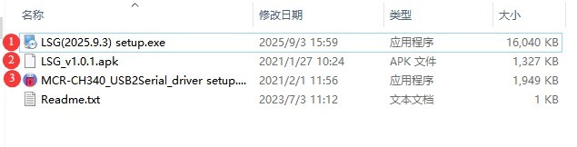
Gambar 0
4.1.3 Penanganan Pengecualian
Jika perangkat lunak antivirus atau Windows Firewall Anda menandai sebuah file sebagai mencurigakan selama proses instalasi perangkat lunak, harap nonaktifkan sementara perangkat lunak antivirus atau Windows Firewall tersebut, lalu coba instal perangkat lunak itu lagi.
4. Perakitan Perangkat Keras
4.1 Persiapan
4.1.1 Preparing Tools
| Nama | Note |
| Pita pengukur | At least 10 meters in total length |
| Bor Palu | Drill bit sizes: φ 8, φ 10, and φ 12 |
| Obeng | One set each of Phillips screwdrivers, flathead screwdrivers, and Allen wrenches |
| Double-ended wrench | Satu set |
| 12-inch Adjustable Wrench | Bukaan maksimum: 36 mm |
| Electric or Manual Forklifts | Load capacity: 2 metric tons; lifting height: 1.6 meters. Front fork length: 1.2 meters; width: 0.6 meters |
| Other Common Tools | Gloves, hammers, pliers, electrical tape, paper, pens, etc. |
Forklift Listrik:

Gambar 1
Truk Palet Manual:
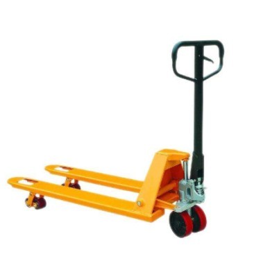
Gambar 2
4.1.2 Darkroom Preparation
Please confirm that the darkroom has been constructed exactly according to the darkroom drawings we provided. If there are any discrepancies in the actual dimensions, please let us know in advance so we can adjust the installation plan to ensure that installation and commissioning proceed smoothly and that test results are accurate.
According to the darkroom drawings, there is a circular black cover in the exact center of the light-passing opening in the partition near the LSG-6000 Goniophotomoeter main unit. However, please do not install this cover yet; wait until all installation and commissioning steps are complete before installing it.
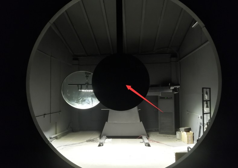
Gambar 2.1
4.2 Cabinet Equipment Assembly
4.2.1 Introduction to the Cabinet
Place the cabinet on a level, sturdy workbench, leaving sufficient space for operation.
| Jumlah | Note |
| ① | Wiring Diagram: Please assemble the equipment according to the wiring diagram. |
| ② | Power distribution panel, used to connect the power cords of all devices inside the cabinet |
| ③ | Cooling fan power cord: Please connect it to the power strip inside the cabinet. |
| ④ | RS-485 Communication Box, used to connect all devices via an RS-485 communication cable |
| ⑤ | Please connect the power adapter for the RS485 communication box to the power strip inside the cabinet. |
| ⑥ | The USB cable for the RS485 communication box needs to be connected to the computer. |
| ⑦ | RT-300C Angle Controller Wiring |
| ⑧ | LS Series Power Meter Wiring |
| ⑨ | Koneksi Daya DC |
| ⑩ | AC Power Wiring |
| ⑪ | The main power cable for the cabinet, which supplies power to all equipment inside the cabinet, should be routed through cable opening ② and connected to the power source only after all equipment has been fully assembled. |
| 1 | Cable opening—the main power cord can be routed through here. Note: The main power cord plug is a Chinese standard plug; you may need to provide an adapter. |
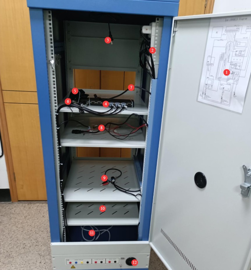
Gambar 3
4.2.2 RT-300C Installation
For now, all you need to do is plug it in.
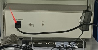
Gambar 4
4.2.3 Installation of the LS Power Meter
| Jumlah | Note |
| ① | Connected via an RS-485 communication cable; the other end is already connected to the RS-485 communication box inside the cabinet. |
| ② | The power cord is connected; the other end is already connected to the power distribution panel inside the cabinet. |
| ③ | V1 test lead, connected to the red terminal of the power meter’s voltage V |
| ④ | V2 test lead, connected to the black terminal of the power meter’s voltage V |
| ⑤ | A1 test lead, connected to the red terminal of the power meter’s current A |
| ⑥ | A2 test lead, connected to the black terminal of the power meter’s current A |
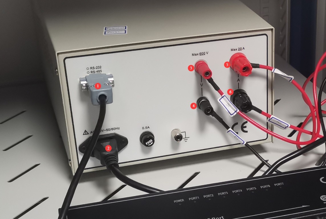
Gambar 5
4.2.4 DC Power Supply Installation
| Jumlah | Note |
| ① | Connected via an RS-485 communication cable; the other end is already connected to the RS-485 communication box inside the cabinet. |
| ② | Connect the DC power output wires, making sure to match the positive and negative terminals. |
| ③ | Kabel daya sudah terpasang; ujung lainnya sudah terhubung ke stopkontak di dalam kabinet. |
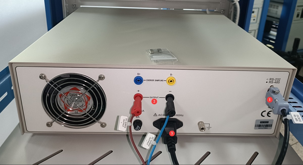
Gambar 6
4.2.5 Instalasi Daya AC
Please locate the following AC power cord among the accessories:
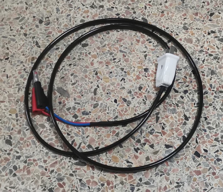
Gambar 7
| Jumlah | Note |
| ① | Connected via an RS-485 communication cable; the other end is already connected to the RS-485 communication box inside the cabinet. |
| ② | The power cord is connected; the other end is already connected to the power strip inside the cabinet. |
| ③ | Run the AC power output cord through port ④ to connect it to position ⑤. |
| ④ | Lubang kawat |
| ⑤ | Run the AC power output cable through cable opening ④ and connect it to position ③. |
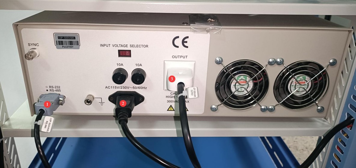
Gambar 8
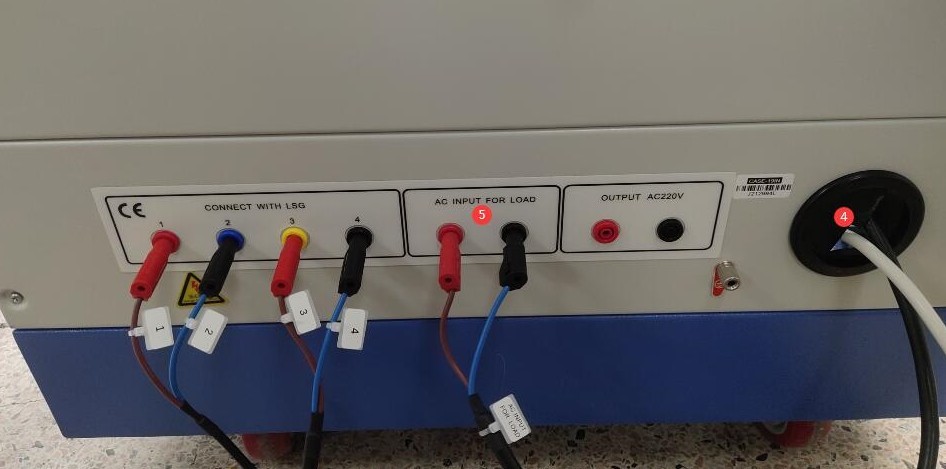
Gambar 9
4.3 Assembly of the LSG-6000 Goniophotomoeter
4.3.1 Assembly of the Main Unit, Light Shaft, and Base
4.3.1.1 Main Unit and Base
Position the main unit and the base in the appropriate locations according to the darkroom drawings. Use the drawings below as an example.
| Jumlah | Note |
| ① | LSG-6000 location—this is where you can place the main unit and the base |
| ② | Position of the far-field photometric probe; assembly will be done later |
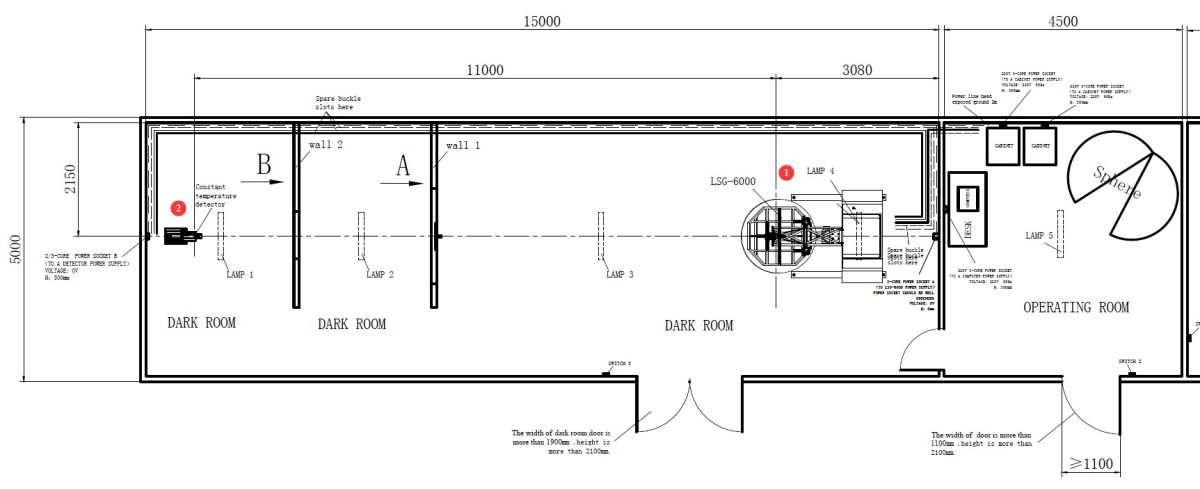
Gambar 9.1
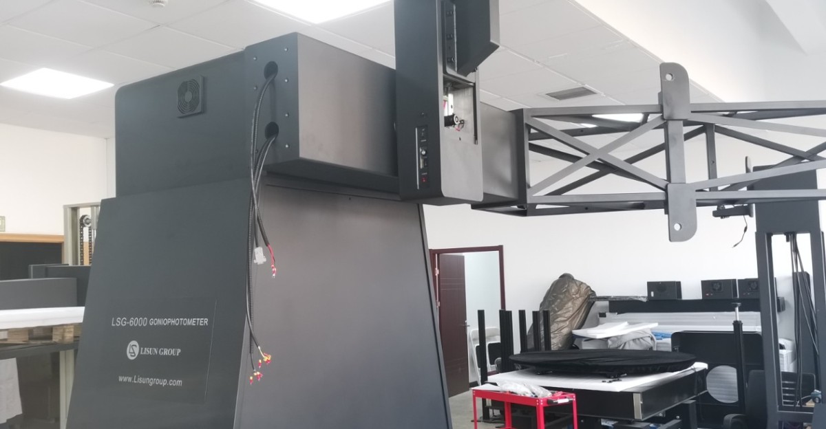
To facilitate shipping, the LSG-6000 and higher-model units are disassembled into two parts for transport. Place the base and the main unit as shown in the illustration below. The front and rear cover plates on the base and the main unit can be removed directly to facilitate assembly.
| Jumlah | Note |
| ① | Host Base |
| ② | The side with the “FRONT” sticker should face the far end of the darkroom—that is, in the direction of the far-field probe. |
| ③ | Load-bearing beams, one on each side |
| ④ | Main unit. Note that the side with the rotating arm faces the far end of the darkroom—that is, the direction of the far-field probe. |
| ⑤ | Some of the wires left exposed here are high-voltage wires that have been wrapped in electrical tape. Please do not remove the electrical tape for the time being to prevent electric shock. |
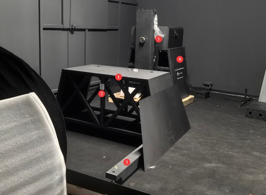
Gambar 10
Note: The base and main unit of the LSG-6000S compact device are assembled before shipment.
Install and secure the two load-bearing crossbeams to the base. The long end of the crossbeams—indicated by the arrows in the figure below—is the far end of the anechoic chamber, which is the direction of the far-field probe.
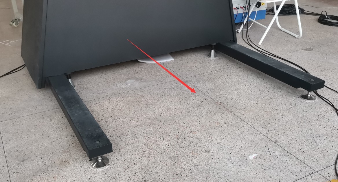
Gambar 11
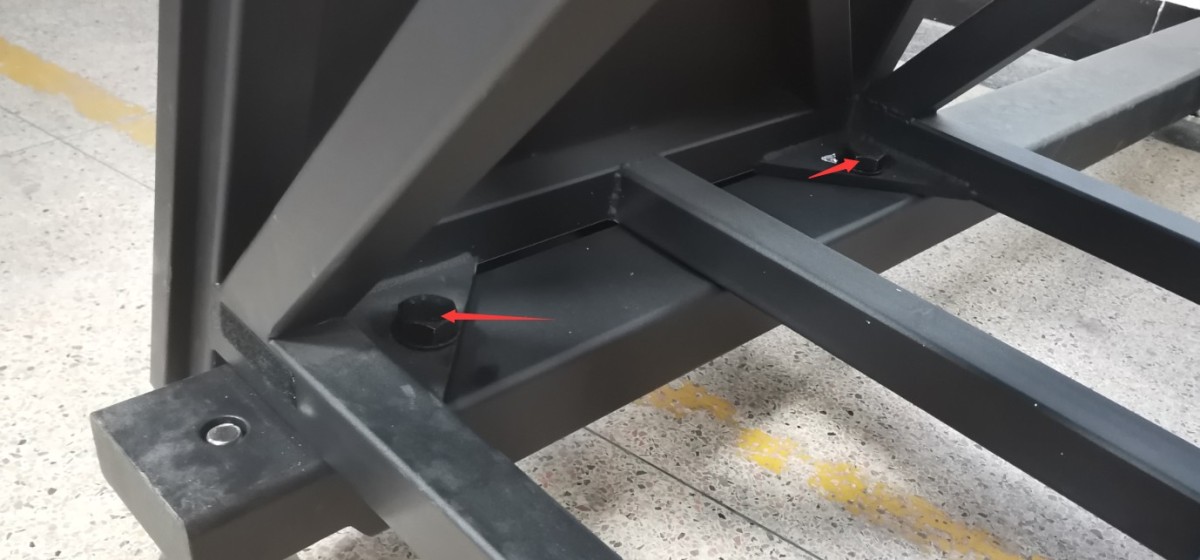
Gambar 12
4.3.1.2 Lamp Shaft Installation
Then locate the light shaft as shown in the figure below.
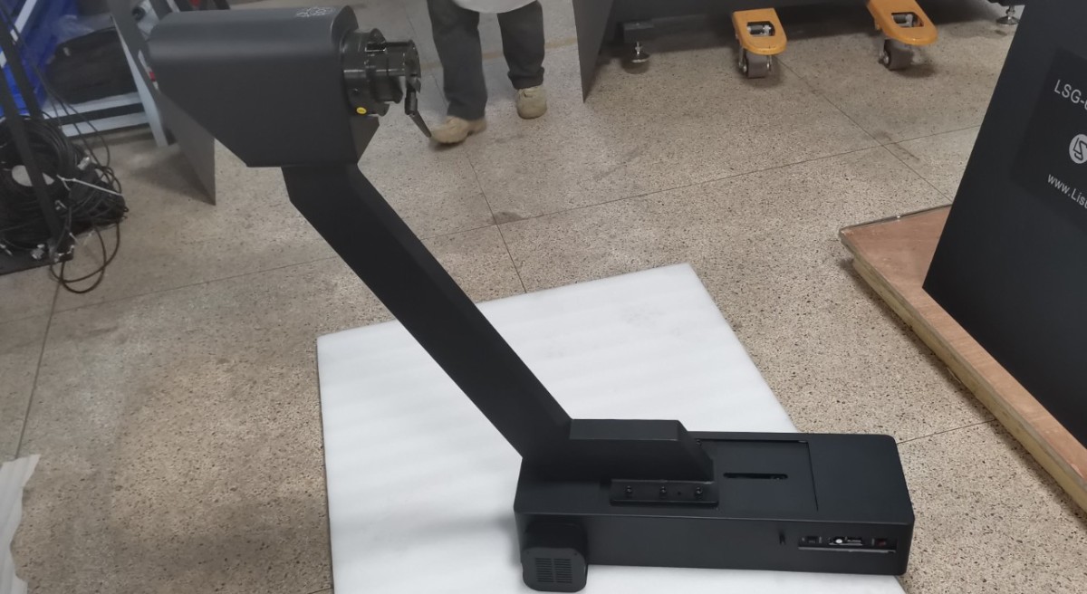
Gambar 13
Remove the screws from the cover here, and pull the cover down.
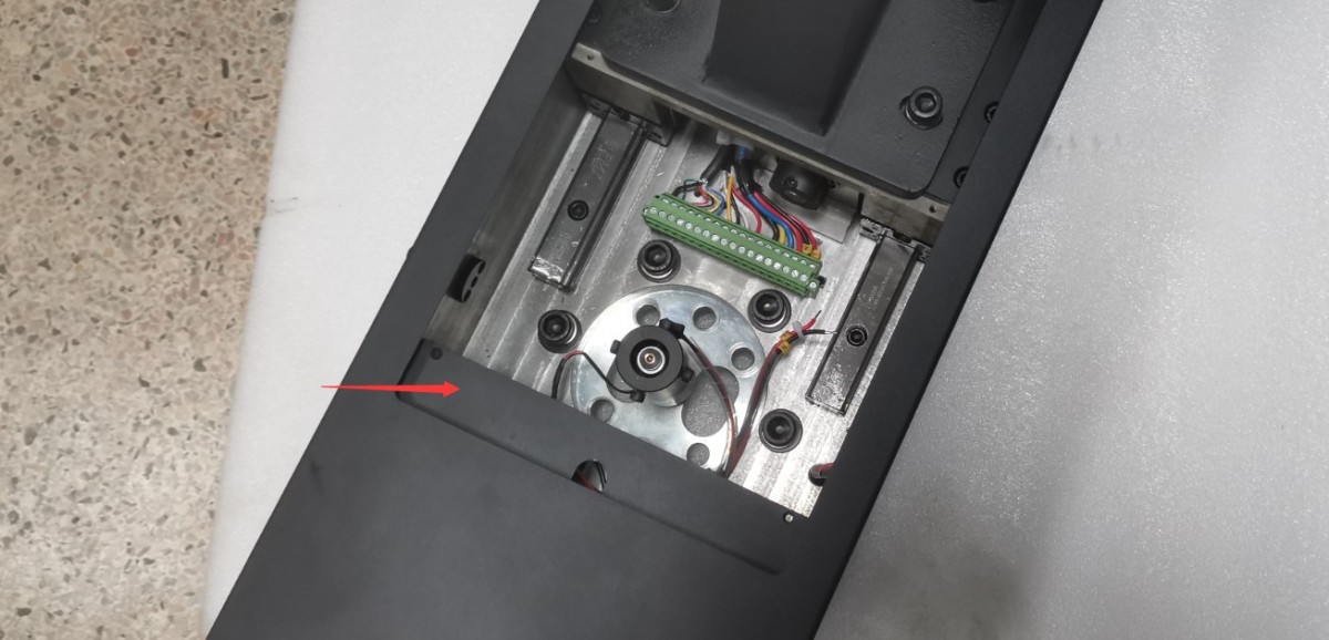
Gambar 14
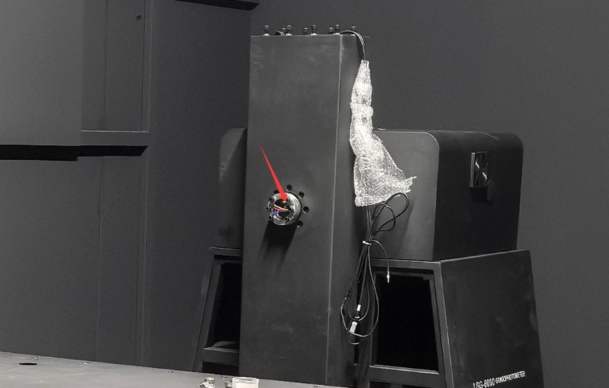
Remove the six Allen screws from the main unit here, then pull out the terminal block and all the wires from inside the center hole.
Gambar 15
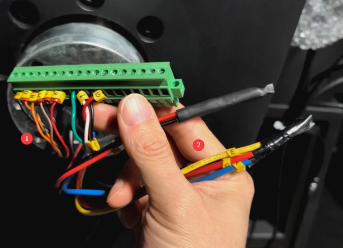
| Jumlah | Note |
| ① | The signal line is on the left. |
| ② | The high-voltage wires are on the right; they must be kept separate from the signal wires to prevent interference. |
Gambar 16
With the lamp shaft facing to the right, lift it into place on the main unit and secure it firmly using the six Allen screws you removed earlier.
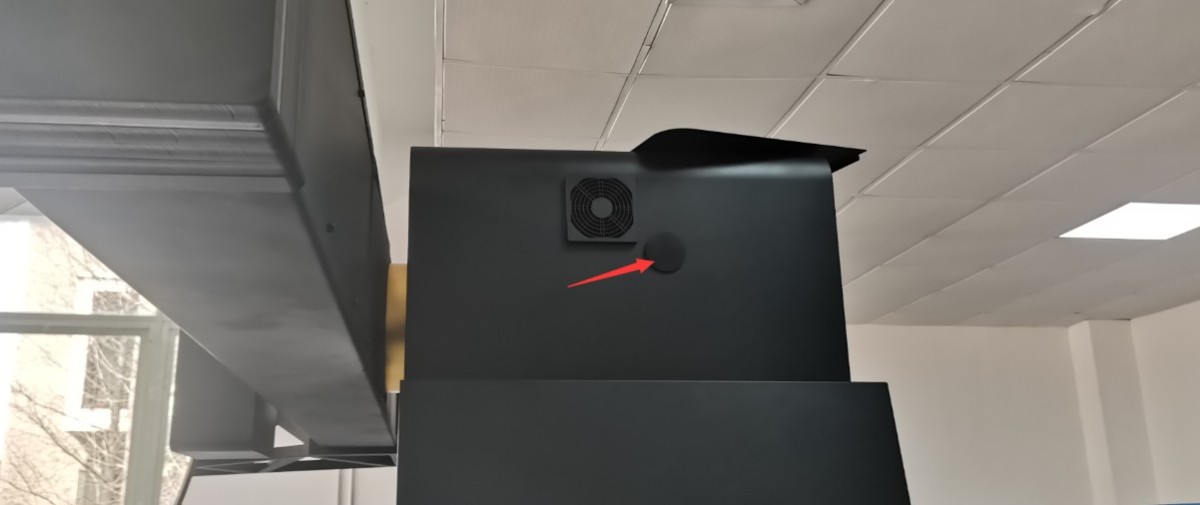
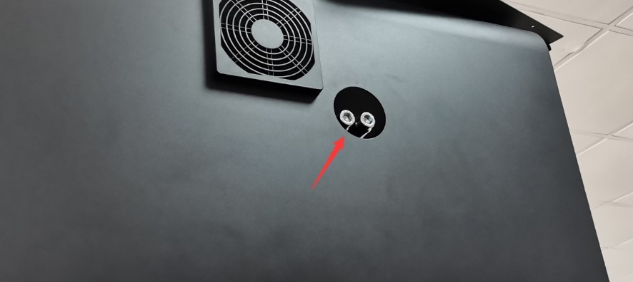
At least two people are needed to support the lamp shaft. Slightly loosen the two large Allen screws on the right side of the main unit (as shown in the figure below) by turning them counterclockwise. Then, manually lift the lamp shaft counterclockwise until it is in a vertical position. Finally, tighten the two screws on the right side of the main unit securely to lock the lamp shaft in the vertical position.
Gambar 17
Gambar 18
Note: These two screws are used to secure the lamp shaft; it takes considerable force to loosen them, so be sure to apply sufficient force when tightening them.
Then connect the cables on the host lamp shaft according to the labels.
| Jumlah | Note |
| ① | The signal line is on the left. |
| ② | The high-voltage wires are on the right; they must be kept separate from the signal wires and routed through two different openings in the light fixture to prevent interference. |
| ③ | Temperature and humidity probe—insert it into the dedicated port on the left side of the lamp shaft |
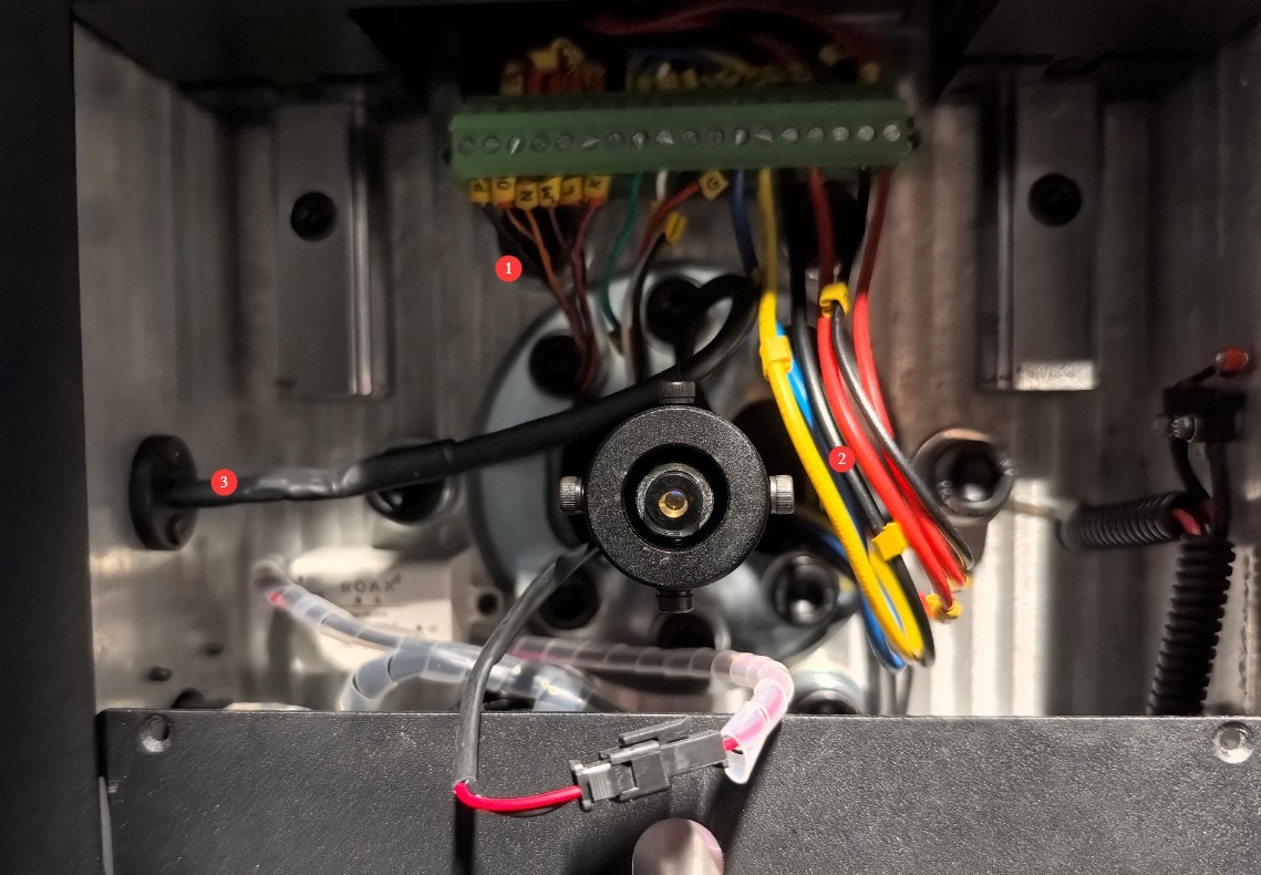
Gambar 19
4.3.1.3 Assembling the Main Unit and Base
The unit is secured to the bottom of the wooden crate with screws; please remove the mounting screws.
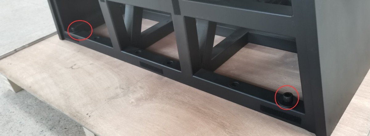
Gambar 20
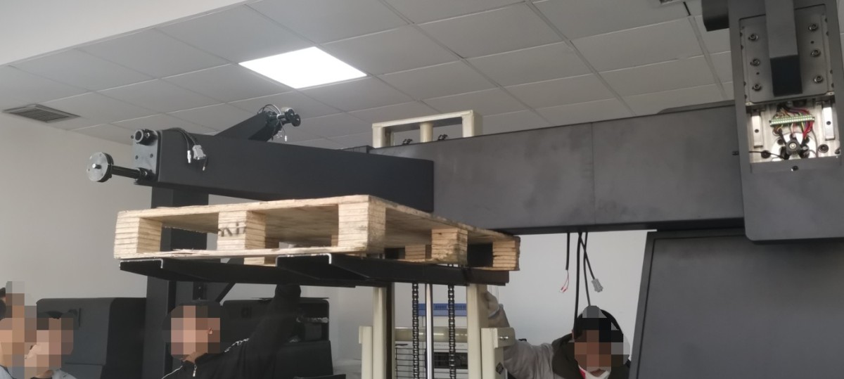
Next, use a forklift to lift the main unit and place it onto the base. Note: If the main unit is equipped with a light shaft at the front, its center of gravity will be shifted forward; take special care to prevent it from tipping over while lifting. Then, securely fasten the main unit to the base at both the front and rear using Allen screws.
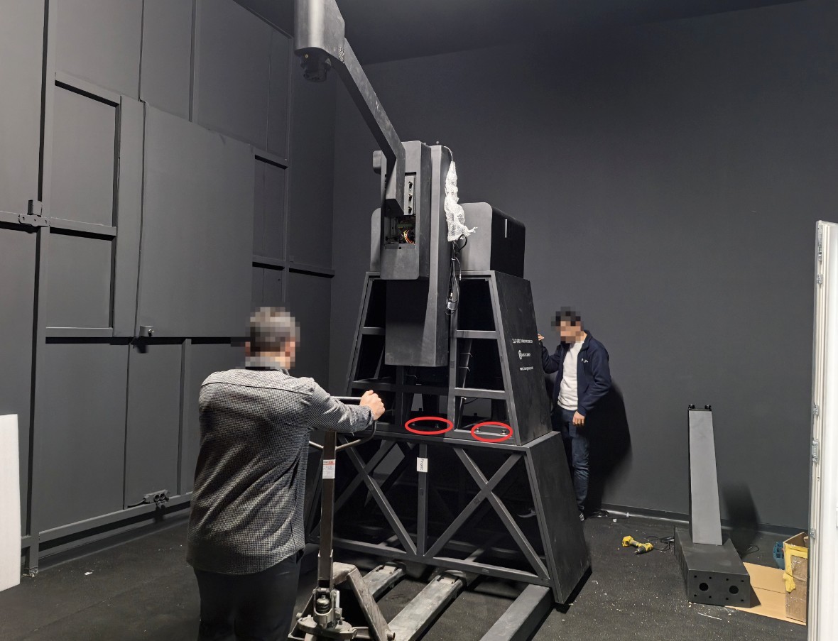
Gambar 21
4.3.1.4 Connecting the Host to the Cabinet
| Jumlah | Note |
| ① | Connect the sample power cables and sampling cables to the cabinet, matching them one-to-one with their respective serial numbers. |
| ② | Kabel Listrik |
| ③ | Please connect a separate ground wire to the main unit of the Goniophotomoeter whenever possible. |
| ④ | RS-485 communication cable, with the other end connected to the RS-485 communication box inside the cabinet |
| ⑤ | If you have a CCD-series model that includes a Spectroradiometer, this package includes an additional RS-485 communication cable, the other end of which connects to the RS-485 communication box inside the cabinet. |
| ⑥ | This is the RS-485 communication cable for the near-field photometer probe; the other end connects to the RS-485 communication box inside the cabinet. |
| ⑦ | Once everything is connected, turn on the host computer. |
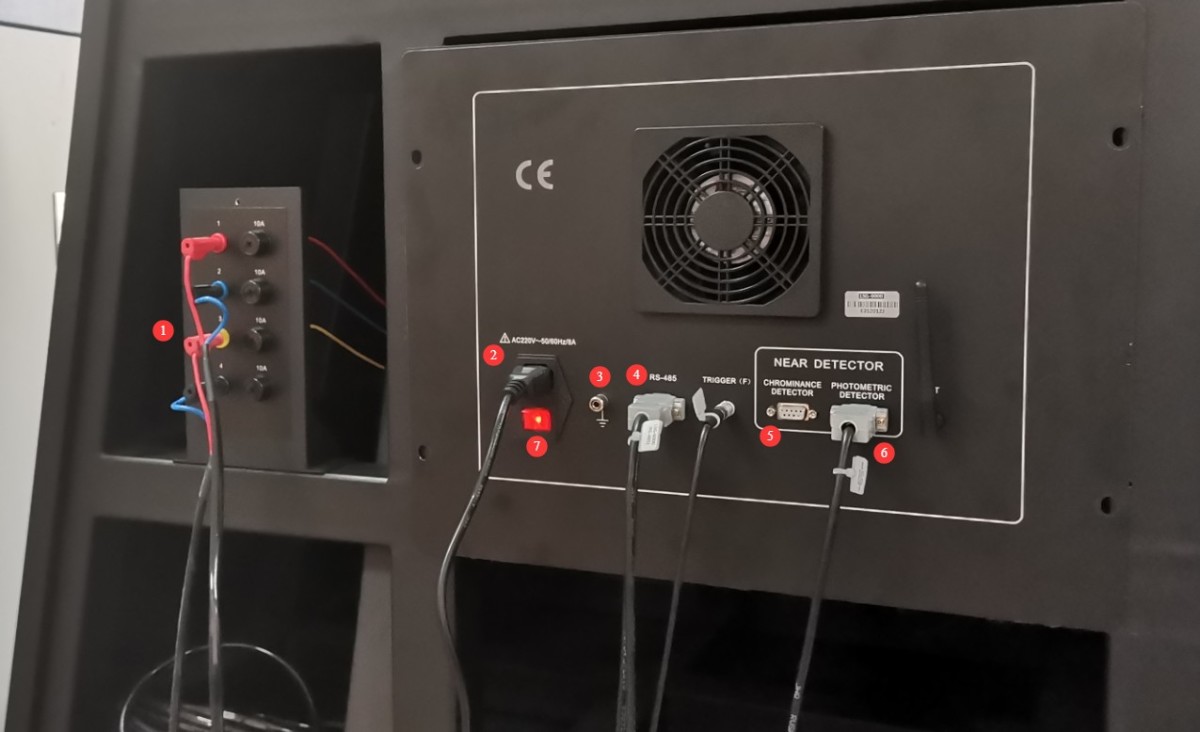
Gambar 22
Next, turn on the main power switch for the cabinet, and then turn on the power to each piece of equipment inside the cabinet one by one.
4.3.2 Assembly of Spindle Components
4.3.2.1 Installing the Rearview Mirror Bracket
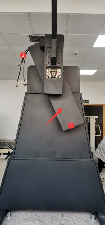
The arrow points to the main axis of the goniophotomoeter (G/Gamma axis).② The end with the wire is used to connect to the near-field probe. The end ①without the wire is used to connect to the reflector.
| Jumlah | Note |
| ① | The end without the pre-installed cable is used to mount the mirror bracket and the mirror. |
| ② | Use this end of the reserved cable to install the near-field mount, the near-field photometer, and the Spectroradiometer. |
Gambar 23
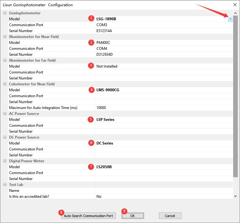
Double-click to open the software; the first time you open it, it will automatically open the system configuration screen.
| Jumlah | Note |
| ① | For the model of the goniophotomoeter, click the drop-down list on the right to select one. The model you purchased is the LSG-6000. |
| ② | Near-field photometer probe; select photometer probe model PM400C |
| ③ | Far-field photometer probe; select photometer probe model PM400C |
| ④ | Near-field spectroradiometer; select spectroradiometer model LMS-9000CG (if available) |
| ⑤ | AC power supply models are typically from the LSP Series |
| ⑥ | DC power supply models are generally designated as the DC Series |
| ⑦ | Power meter model: The model number is printed on the front panel of the power meter. Please check it and select the appropriate model. |
| ⑧ | Once you have selected all the correct models, click “Auto-Detect Port.” |
| ⑨ | Click “OK” to save and exit. |
Gambar 24
Note: If the near-field photometer, far-field photometer, and Spectroradiometer are not currently connected, a “Communication Failed” message will appear during the automatic port search. Simply click “OK.” Once all devices are connected, you can attempt communication again.
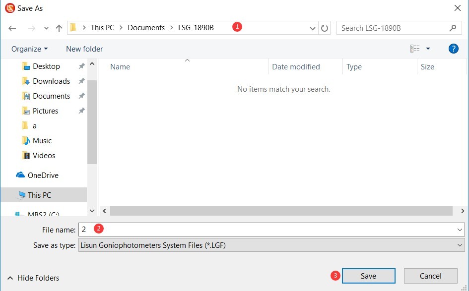
The software automatically opens the screen for saving the database file. After that, all test reports will be automatically saved in this database file.
| Jumlah | Note |
| ① | Please select the path where you want to save the database file. Please do not save it to the desktop or inside the desktop folder. |
| ② | Masukkan nama file |
| ③ | Just click “Save” |
Gambar 25
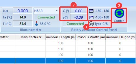
The software will then automatically open to its main interface.
| Jumlah | Note |
| ① | Click to switch angle modes |
| ② | Click ① to display the C-Gamma angle here instead of the B-Beta angle. |
| ③ | Then click to open the angle control interface |
Gambar 26
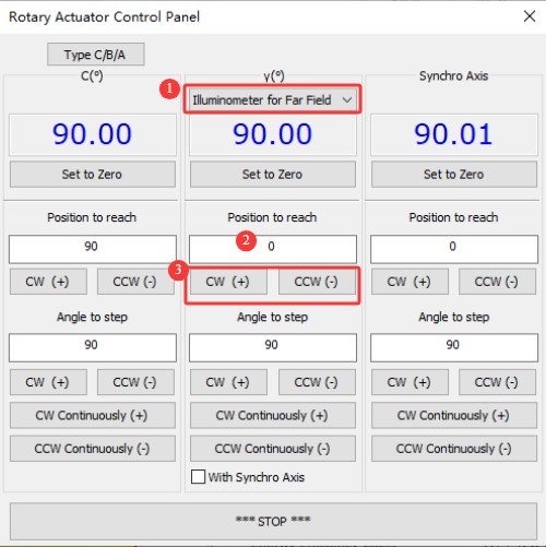
| Jumlah | Note |
| ① | Select a far-field photometric probe from the Gamma angle drop-down list |
| ② | You can enter 0 |
| ③ | Then click in any direction to rotate the mirror bracket’s mounting end so that it faces downward for easier installation. |
Gambar 27
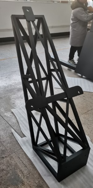
Find the mirror bracket.
Gambar 28
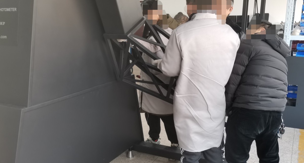
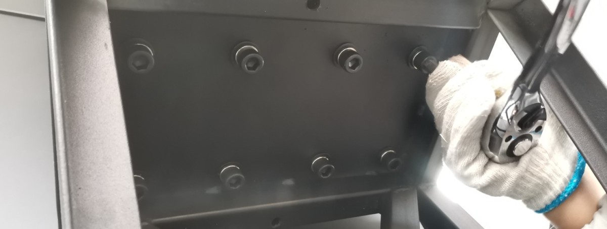
When installing, secure all screw holes firmly with hex screws.
Gambar 29
Gambar 30
4.3.2.2 Installing the Near-Field Bracket
However, the mounting end of the near-field bracket can be rotated to a horizontal position to facilitate installation.
Gambar 31
Note: Before all components are installed on the spindle, the weight distribution at both ends is uneven; therefore, the spindle may not rotate when controlled by the software. This manifests as the software freezing with no response and the spindle failing to rotate. If this occurs, turn off the power to the LSG-6000 Goniophotomoeter main unit, wait one minute, and then turn it back on. Apply a constant force to push or pull the spindle, then simultaneously use the software to control its rotation. Ensure that the external force you apply is in the same direction as the spindle’s rotation. Throughout the process of installing the spindle accessories, you may need to repeat this procedure several times to complete the installation.
Be sure to thread the reserved cable through the holes in the near-field bracket. Then, secure all screw holes firmly using Allen screws.
Gambar 32
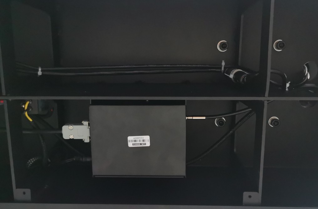
4.3.2.3 Connecting the Near-Field Probe and The Spectroradiometer
Be sure to turn off the power to the LSG-6000 Goniophotomoeter main unit first.
| Jumlah | Note |
| ① | The red and black wires are the power wires; connect them according to the labels. |
| ② | The RS485 communication cable is used to connect the LMS-9000CG Spectroradiometer |
Gambar 34
Gambar 35
Gambar 36
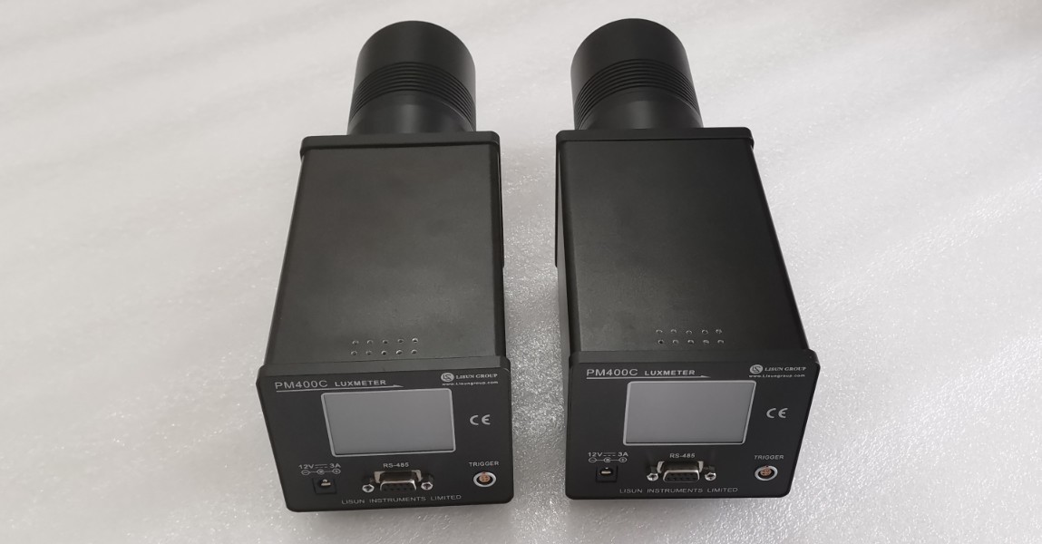
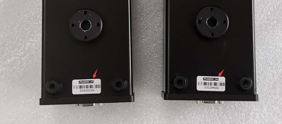
I found the following two photometric probes.
Gambar 37
F stands for far field, and N stands for near field.
Gambar 38
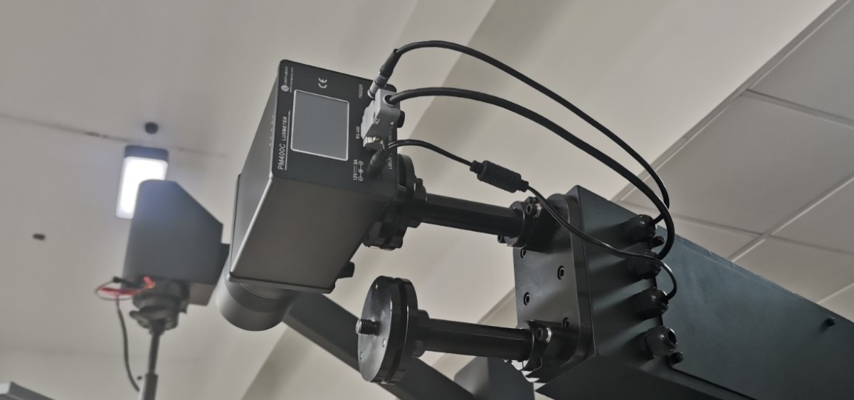
Install the near-field photometer and the Optical Fibre of the Spectroradiometer as shown in the figure below.
Gambar 39
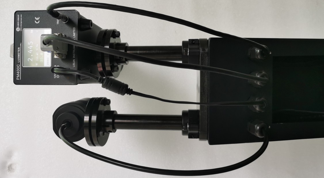
Gambar 40
4.3.2.4 Installing Reflectors
Silakan mulai ulang LSG-6000 goniophotomoeter. The software will control the mirror mount to rotate it to the appropriate lower position.
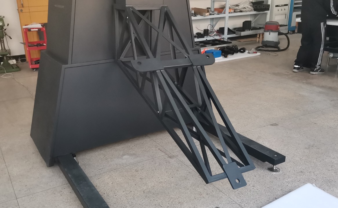
Gambar 41
Locate the reflector. When handling the reflector, be sure to grip the metal bracket on the back of the reflector rather than the reflector itself to avoid damaging it.
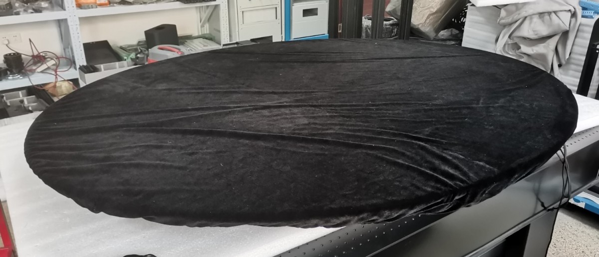
Gambar 42
Align the three screw posts on the reflector with the three holes on the bracket, insert them, and secure each screw post with an inner and an outer screw, as shown in the figure below.
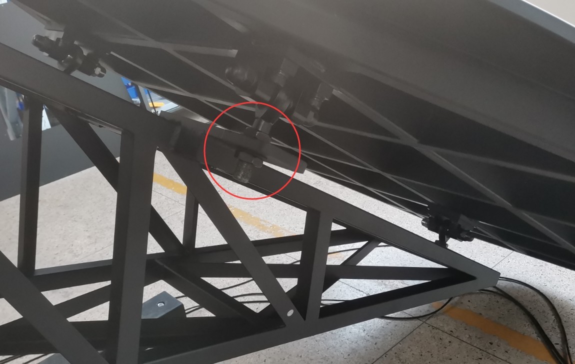
Gambar 43
Once all components on the spindle have been fully installed and the counterweights at both ends are balanced, the spindle will rotate smoothly when the rotation is restarted via software, without the need for any external force.
4.3.3 Installing the Far-Field Photometric Probe
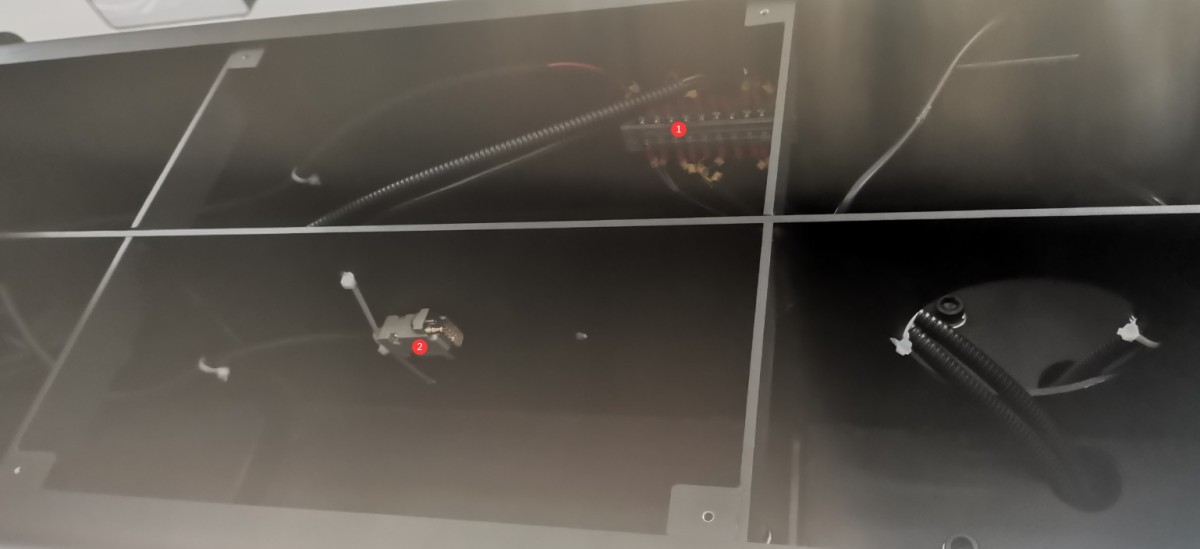
Matikan LSG-6000 Goniophotomoeter main unit to facilitate wiring. The image below shows the internal cables of the main unit; we secure them with cable ties before shipment. Please remove the cable ties first to facilitate wiring.
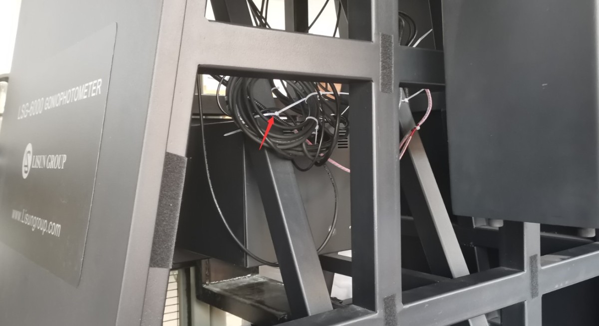
Gambar 44
After removing the cable ties, unscrew the mounting screws on the junction box, and you can pull the junction box out. Then remove the cover to make it easier to connect the wires.
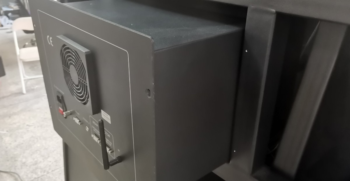
Gambar 45
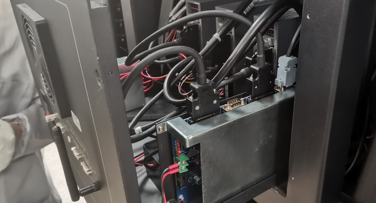
Gambar 46
Locate the far-field photometric probe mount and position it roughly where indicated on the darkroom drawings.
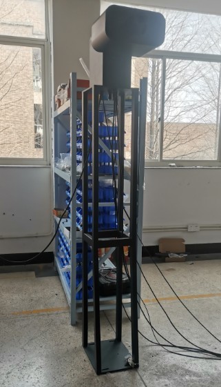
Gambar 47
Cables required to connect the far-field photometric probe.
| Jumlah | Note |
| ① | Power Cable for Far-Field Photometric Probe |
| ② | Trigger wire: According to the cabinet wiring diagram, this must be connected to the host terminal block. |
| ③ | The RS-485 communication cable must be connected to the RS-485 communication box inside the cabinet, as indicated in the cabinet wiring diagram. |
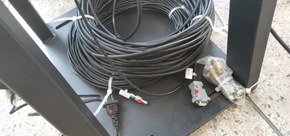
Gambar 48
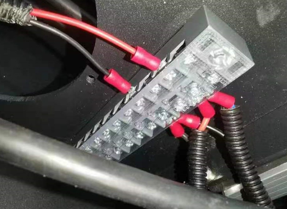
The remaining three wires need to be connected to the junction box inside the main unit.
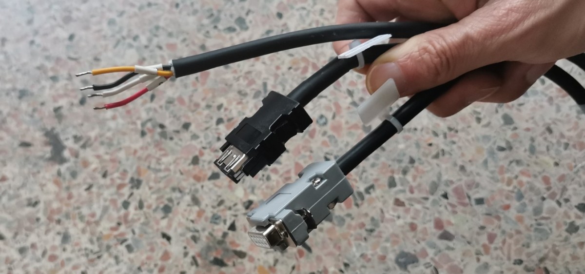
Gambar 49
Starting from the bottom of the console:
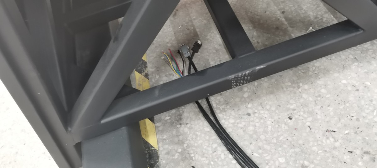
Gambar 50
and feed them through the reserved wiring openings:
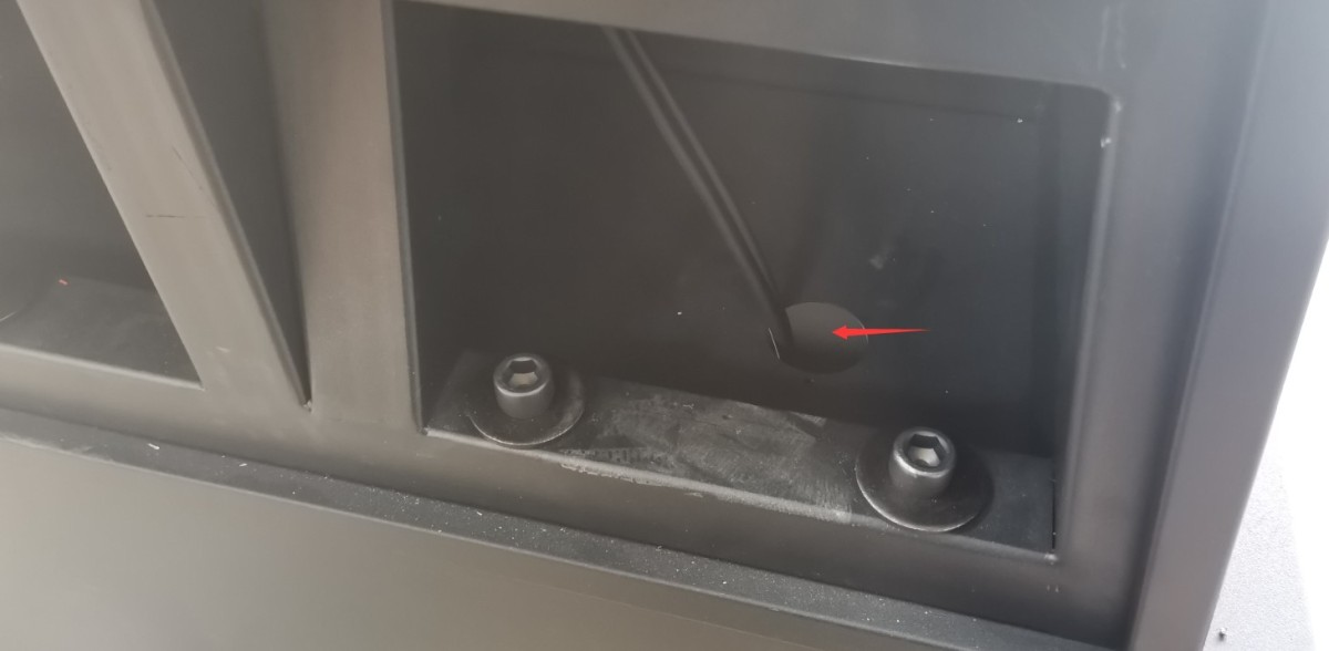
Gambar 51
Then connect these three wires correctly to the three locations shown in the figure below.
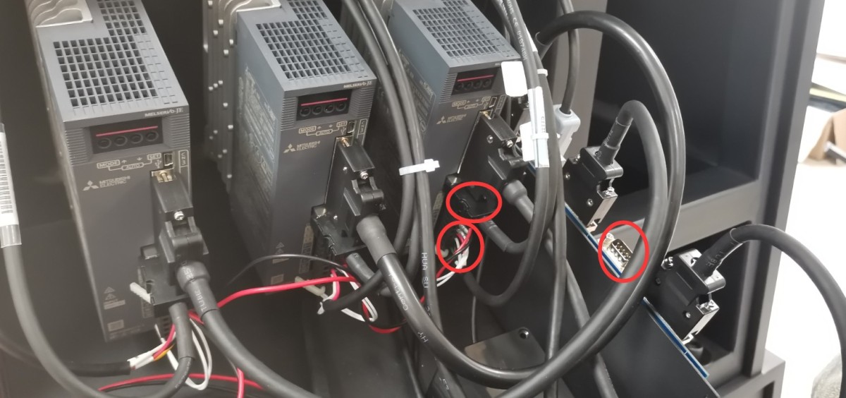
Gambar 52
Note: When connecting the red, yellow, white, and black wires to the terminal block, a wiring tool is provided at that terminal.
Remove the outer sleeve from the far-field probe.
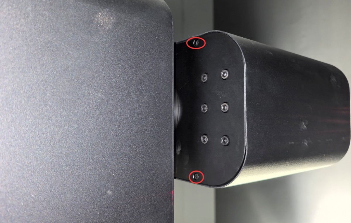
Gambar 53
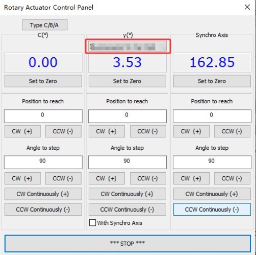
If the angle is incorrect and it is difficult to disassemble, please turn on the power to all devices.
| Jumlah | Note |
| ① | The synchronization axis is the angle of the far-field photometric probe |
| ② | You can enter 90 |
| ③ | Click in any direction to rotate it 90 degrees, making it easier to remove the screws. |
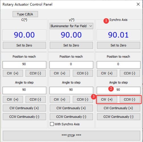
Gambar 54
Install the far-field photometric probe and connect all the wires on the back of the probe.
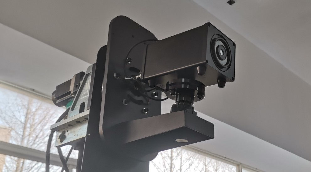
Gambar 55
All hardware connections are complete. All devices are plugged in, and make sure all devices are turned on.
| Jumlah | Note |
| ① | Click the red logo in the upper-left corner of the software |
| ② | Click to return to the system configuration screen. |
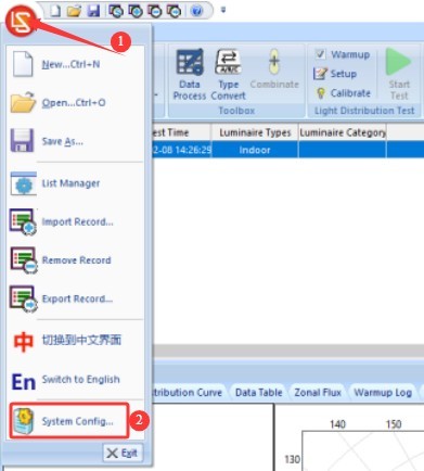
Gambar 56
As described in Section 4.3.2.1, please ensure that all devices are successfully communicating.
5. Calibration of darkroom equipment (Each step must be performed carefully and thoroughly; otherwise, it may result in incorrect calibration data and abnormal test results.)
5.1 Single-Line Laser Calibration
Turn on the single-button laser power switch.
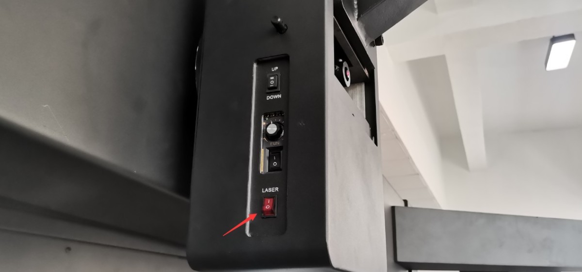
Gambar 57
The single-character laser was turned on.
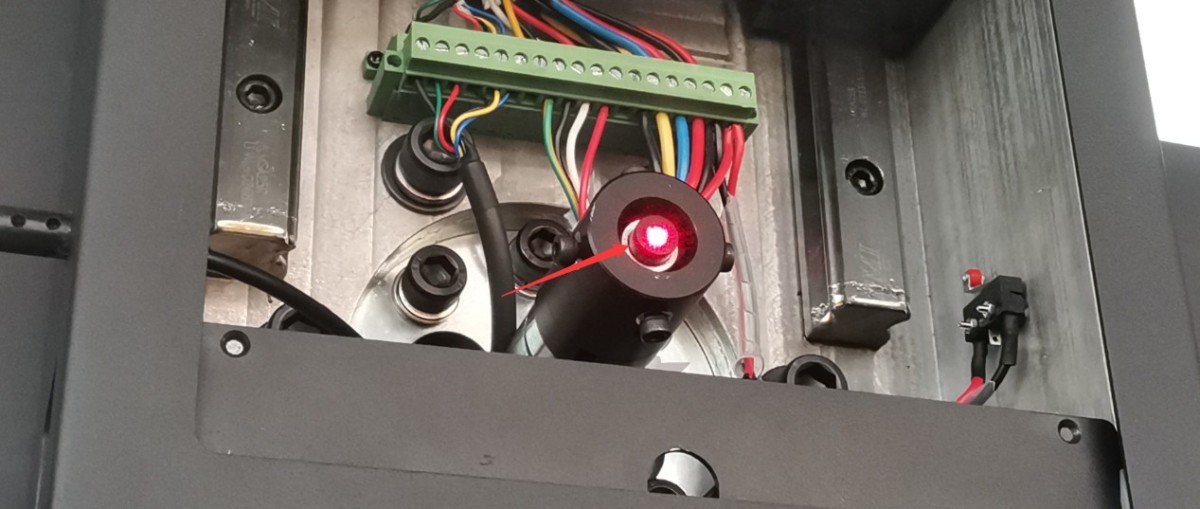
Gambar 58
Rotate the main shaft of the Goniophotomoeter to the position shown in the figure below to facilitate the following steps.
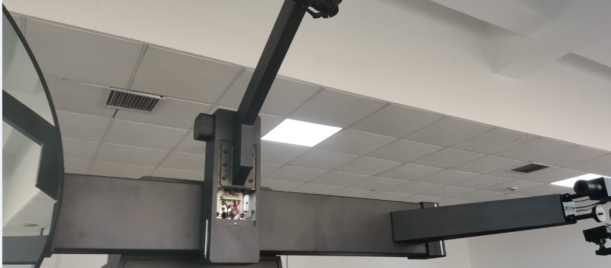
Gambar 59
Please hold the lamp shaft steady and loosen these two screws again.
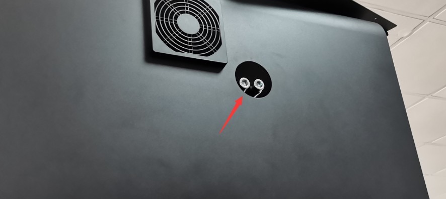
Gambar 60
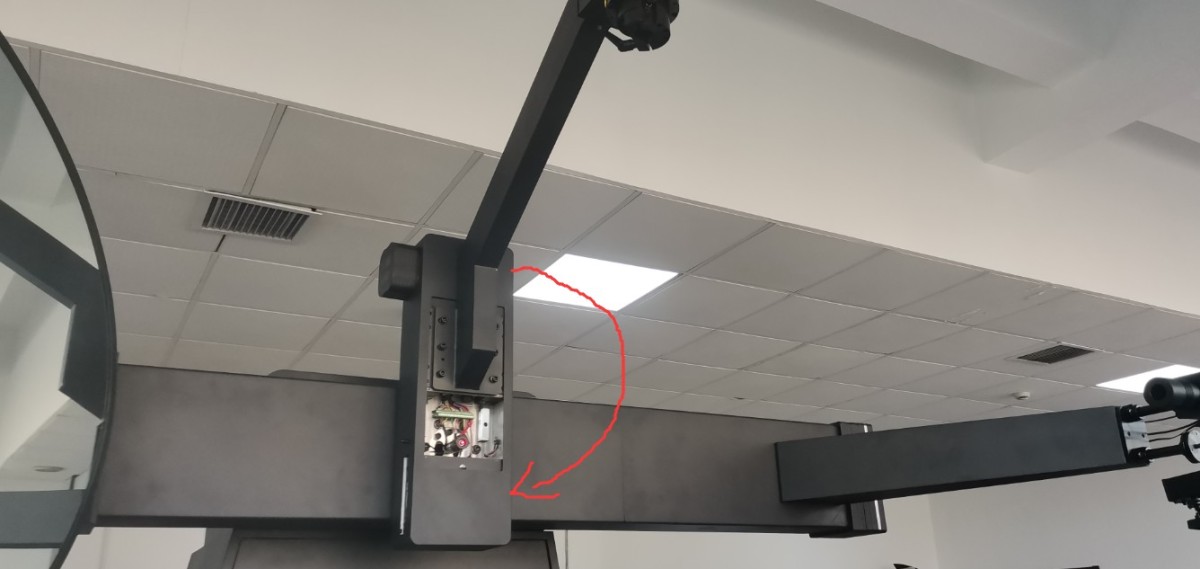
Hold the lamp shaft steady and slowly rotate it 180 degrees clockwise in the direction shown in the figure below.
Gambar 61
Note: A counterclockwise stop has been installed at this point on the lamp shaft, so it can only be rotated clockwise.
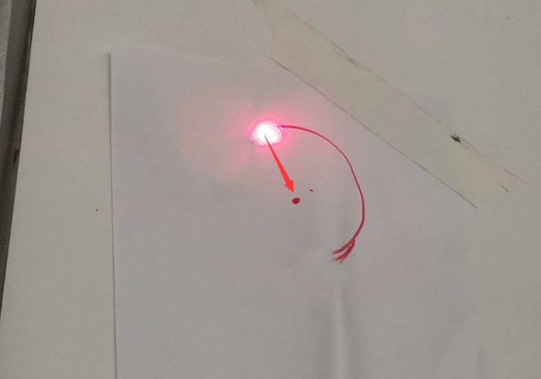
The straight laser beam from the main unit will then trace a semicircular path on the wall opposite the darkroom. You can attach a sheet of white paper to the wall and trace the laser path with a water-based marker. If the radius of the semicircle is very small (for example, 0.5 centimeters) or even close to a single point, no adjustment is necessary. If the radius of the semicircle is larger, adjust the four small Allen screws around the straight-line laser to position the laser spot at the center of the semicircle.
Gambar 62
Once adjusted, hold the lamp shaft steady and rotate it 180 degrees counterclockwise to return it to its original position, while rechecking that the straight laser beam’s path meets the requirements. After debugging, ensure that all four small Allen screws on the straight laser are fully tightened. Rotate the lamp shaft back to its initial position and hold it steady, then fully tighten the two large screws on the side of the main unit to secure the lamp shaft.
5.2 Adjusting the Host’s Position
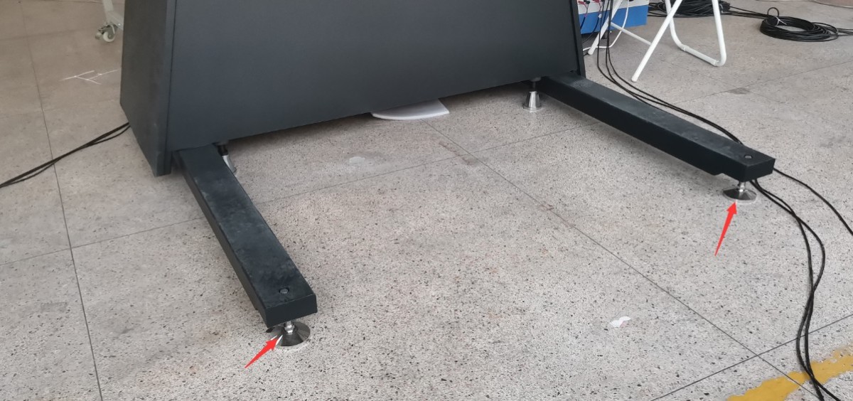
First, move the main unit to its approximate location based on the darkroom blueprints. Then, fine-tune the position of the main unit and adjust the height of all the large screws on the support beam to adjust the main unit’s tilt angle.
Gambar 63
Ensure that the host’s final position meets the following two conditions.
① The single-line laser passes through the exact center of the light-transmitting holes in all the partitions.
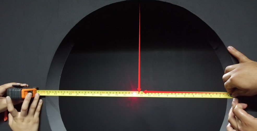
Gambar 64
② The light shaft must be vertical (with no tilt in any direction); you can use a cross-line laser to verify this.
Find the cross-hair laser and the tripod.
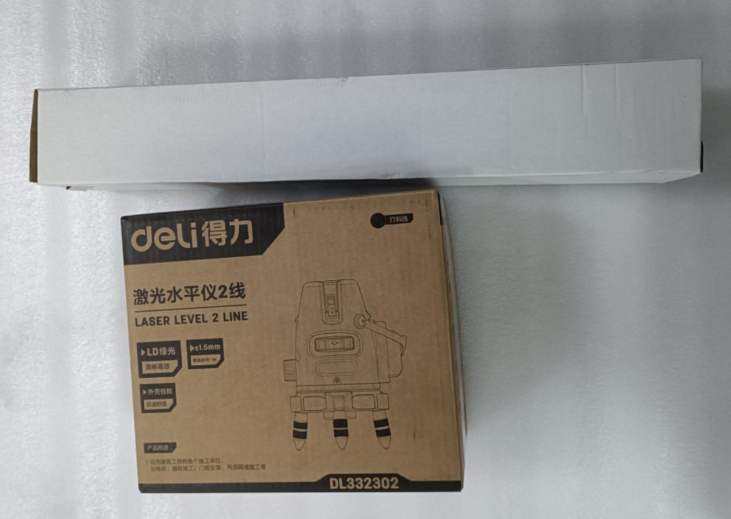
Gambar 65
Remove the cross-line laser and the batteries. Insert the batteries into the cross-line laser. The power switch is located on the side of the device. Turn the switch to the “unlock” position to turn on the device.
| Jumlah | Note |
| ① | Power switch: Move it to the “Unlock” position to turn on the power. |
| ② | VH refers to vertical and horizontal laser switches, respectively |

Gambar 66
Note: The cross-line laser is self-leveling. If it is not self-leveled, an audible alarm will sound. This may be due to an uneven surface or an improperly set up tripod. Please ensure that the cross-line laser remains self-leveled at all times during use.
5.3 Adjust and Secure the Far-Field Luminance Probe Mount
There is a small mirror inside the standard light box; remove it.
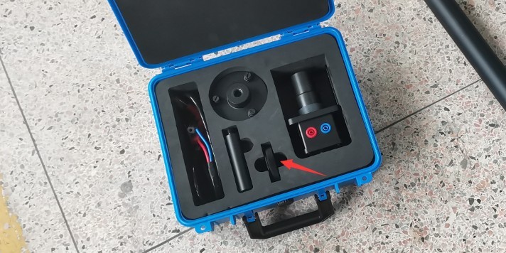
Gambar 67
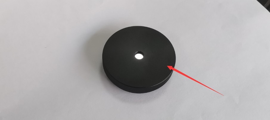
Gambar 68
Temporarily remove the far-field photometer probe, then install the small mirror in the position shown in the figure below.
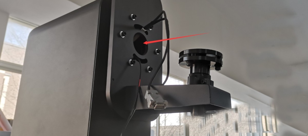
Gambar 69
Please adjust the position of the far-field probe bracket. Then remove the screws shown in the figure below.
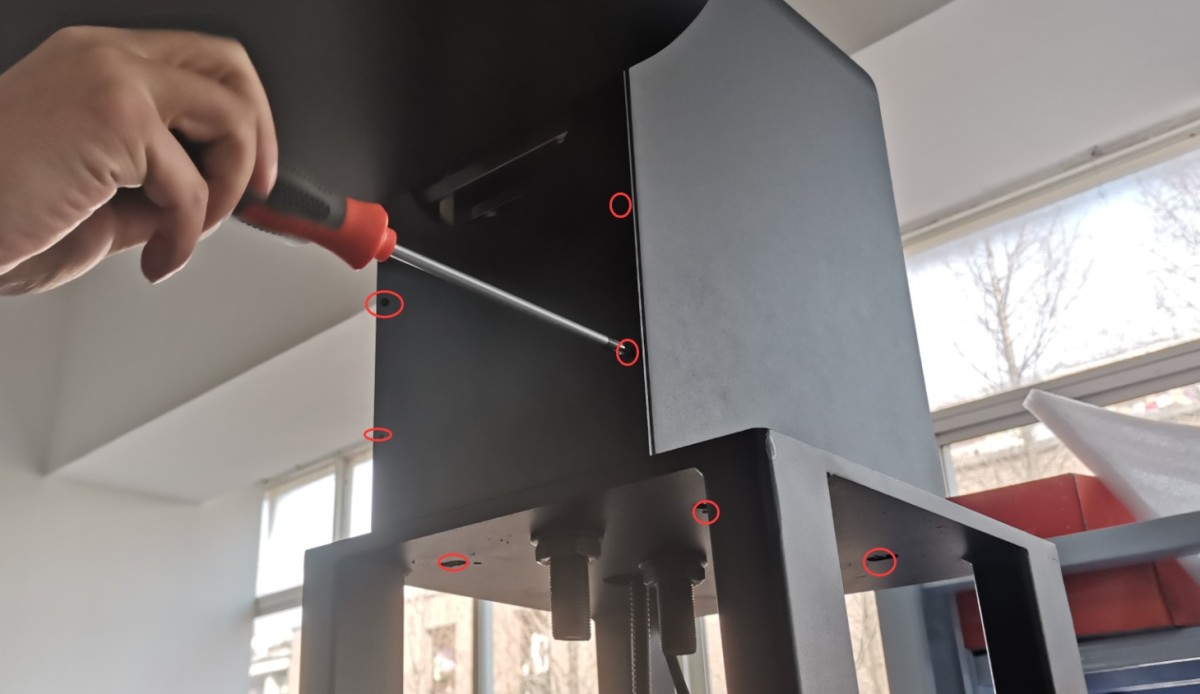
Gambar 70
You can adjust the height of the probe bracket by turning the two pairs of large screws here.
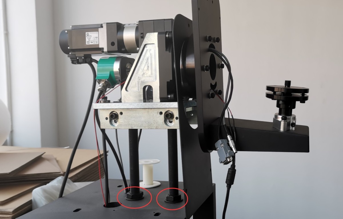
Gambar 71
The goal is to have the straight laser beam from the host unit strike the exact center of the small mirror, so that the reflected straight laser beam travels back along the same path.
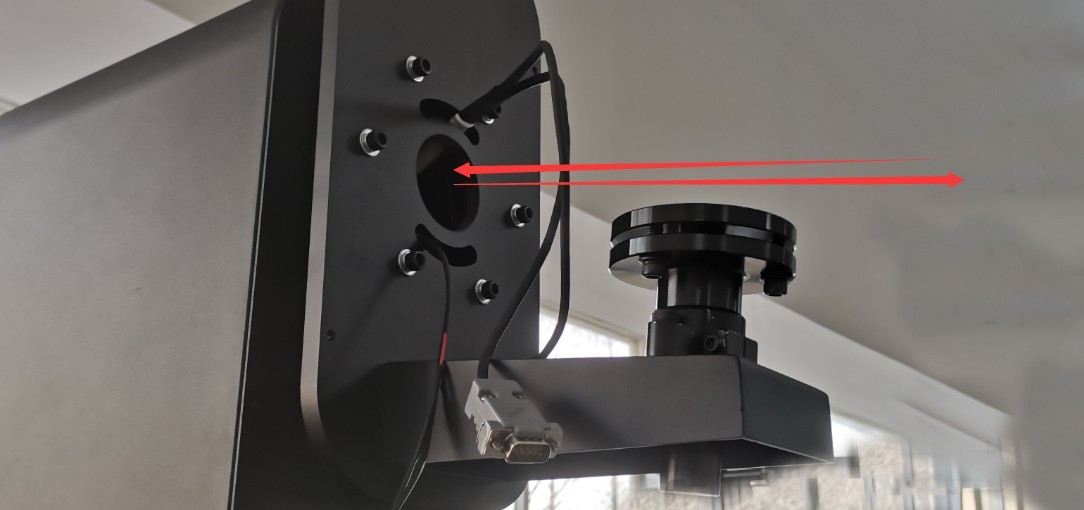
Gambar 72
Once the location has been determined, use expansion screws to secure the probe bracket base to the floor.
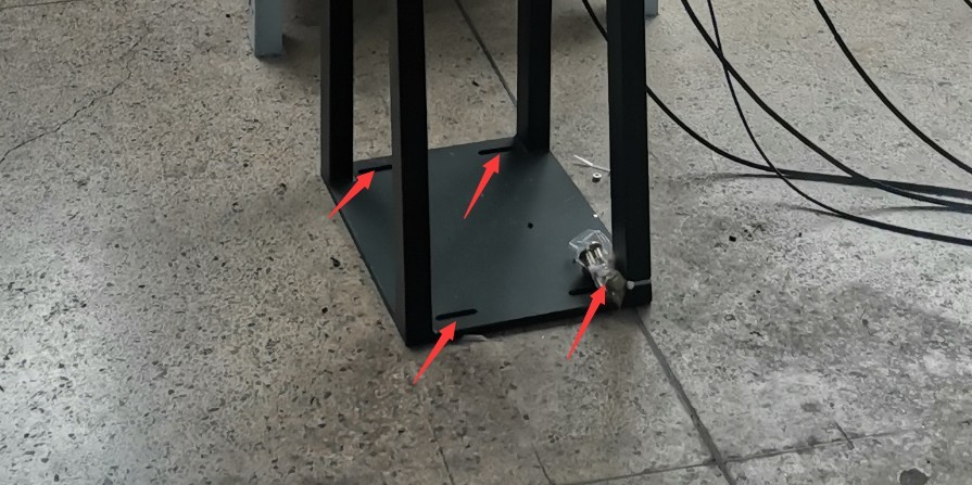
Gambar 73
Once it is securely fastened, double-check that the straight laser beam coming from the main unit hits the small mirror and that the reflected beam follows the same path back. After adjusting and securing it, you can remove the small mirror.
Reinstall the far-field photometric probe. Then attach the small mirror to the probe, as shown in the figure below.
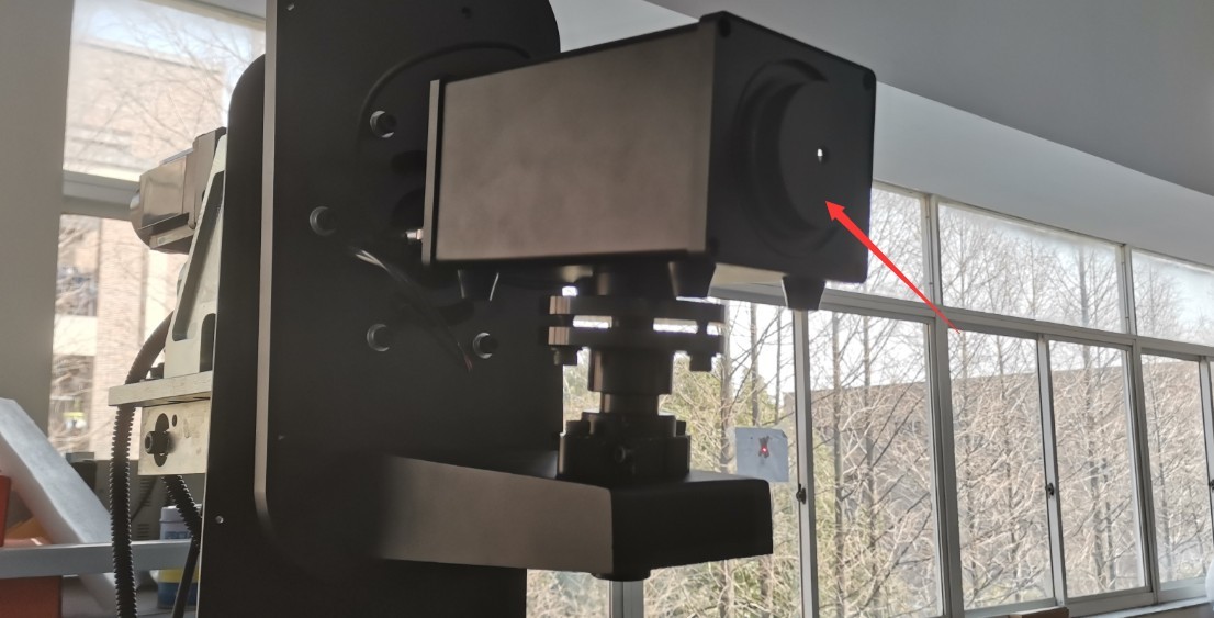
Gambar 74
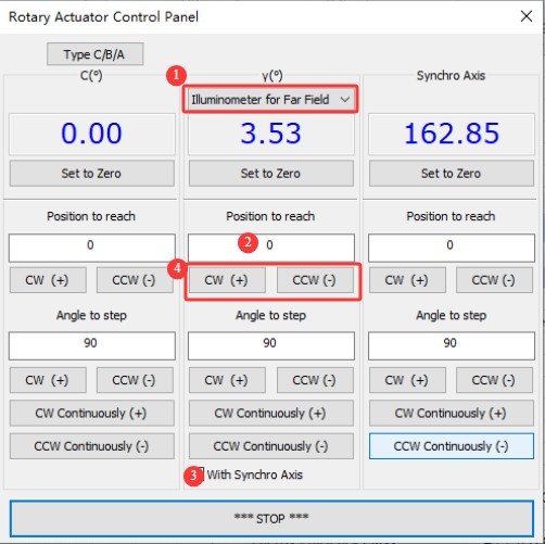
5.4 Setting the Spindle’s 0-Degree Position
| Jumlah | Note |
| ① | Still opting for a far-field photometric probe |
| ② | Masukkan 0 |
| ③ | Check the “Synchronize Axis” box |
| ④ | Click any button to simultaneously rotate the main shaft and the synchronous shaft (i.e., the far-field photometric probe) to the 0-degree position; at this point, the reflector should be directly below the main shaft. |
Gambar 75
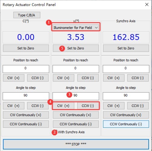
Use the cross-hair laser to verify that the main axis is perpendicular to the lamp axis. If not, use the following method to fine-tune the main axis until it is perpendicular, then set it to 0 degrees.
| Jumlah | Note |
| ① | Still opting for a far-field photometer |
| ② | Please always check the “Sync Axis” box. |
| ③ | Based on the actual situation, enter a small angle, such as 1, 0.5, 0.1, 0.05, etc. |
| ④ | Based on the actual situation, choose a direction to rotate. Repeat steps ③ and ④ until the spindle is rotated to a vertical position. |
| ⑤ | Click to set the current angle to 0 degrees. Password: LISUNGROUP |
Gambar 76
5.5 Adjusting the Direction of the Reflector and the Far-Field Photometric Probe
| Jumlah | Note |
| ① | There is a switch at the top of the lamp post; turn the switch on. |
| ② | A straight laser beam will be projected downward from the center of the lamp shaft. |
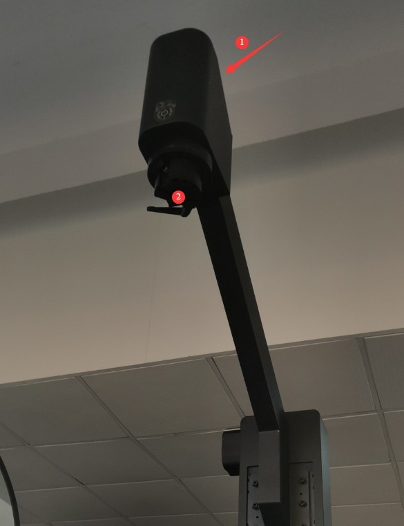
Gambar 77
You need to adjust the three sets of screws on the fixed rearview mirror to adjust the mirror’s reflection angle.
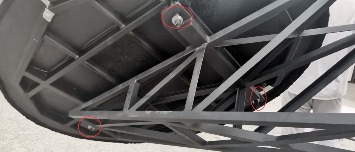
Gambar 78
At the same time, you’ll need to adjust the screws on the far-field photometer probe bracket to change the height and orientation of the far-field photometer probe.
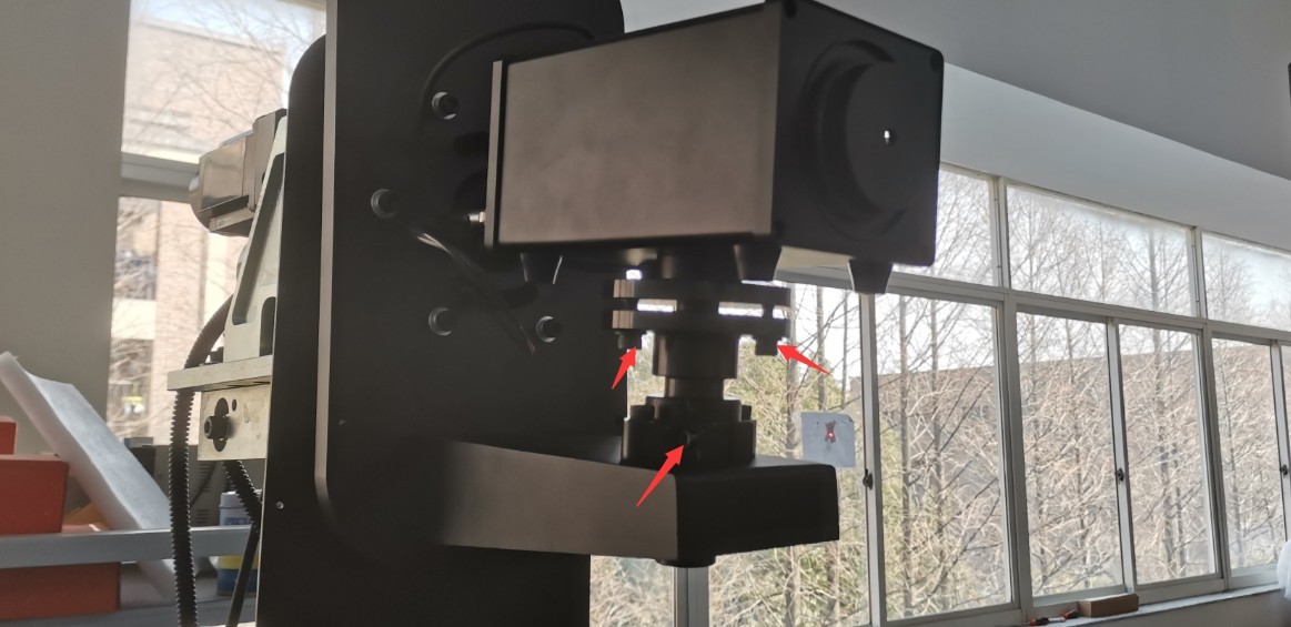
Gambar 79
This causes the straight laser beam emitted downward from the lamp shaft to strike the reflector; after being reflected by the reflector, it strikes the exact center of the small mirror on the far-field photometer probe, and after being reflected once more, it returns along the same path.
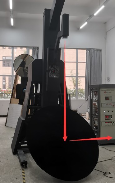
Gambar 80
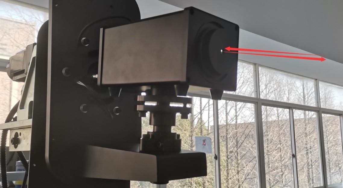
Gambar 81
Once calibration is complete, all screws should be fully tightened. Remove the small mirror attached to the far-field photometric probe, and reinstall the far-field probe sleeve and housing.
5.6 Adjusting the Near-Field Photometric Probe
| Jumlah | Note |
| ① | Selecting a Near-Field Photometric Probe |
| ② | Masukkan 0 |
| ③ | Choose one of the following: Rotate the near-field photometer probe to the 0-degree position. |
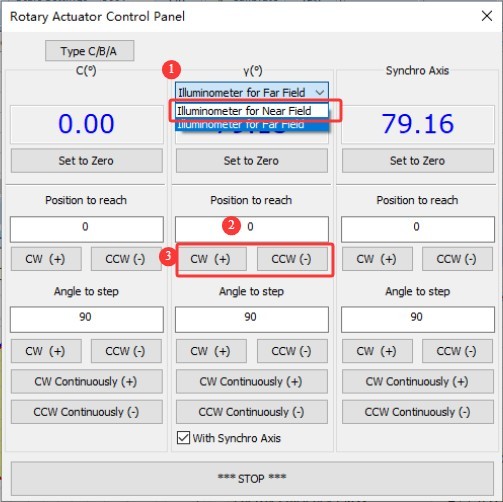
Gambar 82
Attach the small mirror to the near-field photometer. Adjust the position and orientation of the near-field photometer by turning the screws on its mounting bracket so that the laser beam from the lamp axis strikes the exact center of the small mirror and the reflected light returns along the same path. Once adjusted, all screws should be fully tightened.
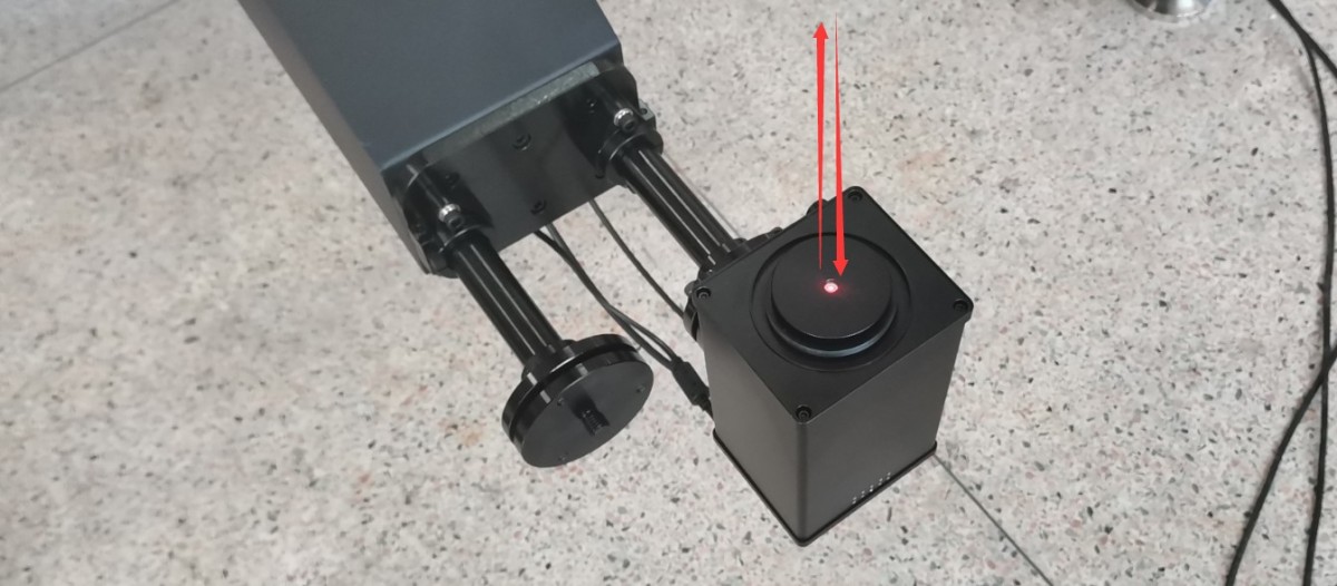
Gambar 83
If the angle is too far off and cannot be adjusted to the correct position, you may need to do the following.
| Jumlah | Note |
| ① | Still opting for a near-field photometer |
| ② | Based on the actual situation, enter a smaller angle, such as 1, 0.5, 0.1, etc. |
| ③ | Based on the actual conditions, rotate the near-field photometer in one direction by the angle entered above. Then readjust the position and orientation of the near-field photometer until the laser beam from the lamp axis hits the exact center of the small reflector and the reflected light returns along the same path. Once adjusted, all screws should be fully tightened. |
| ④ | Then click to reset the 0-degree position for the near-field photometric probe. Password: LISUNGROUP |
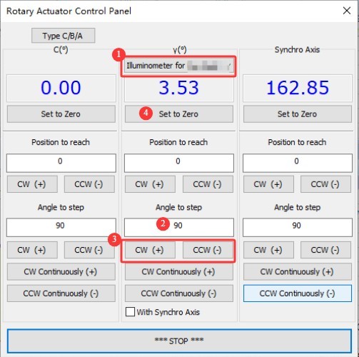
Gambar 84
5.7 Adjusting the Direction of The Optical Fiber Cable
Select a spectroradiometer.
Gambar 85
For the remaining steps, please refer to Section 5.6. Once the adjustment is complete, you can turn off the flat-head laser switch on the lamp shaft.
5.8 Installing the Baffle and Cross-Line Laser
The dimensions marked in the figure below are the dimensions of the baffle.
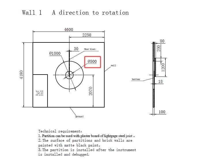
Gambar 86
| Jumlah | Note |
| ① | Install the baffle so that it is centered over the light hole in the first partition. |
| ② | The straight laser beam from the host center should also be aimed at the exact center of the baffle; please mark it. |
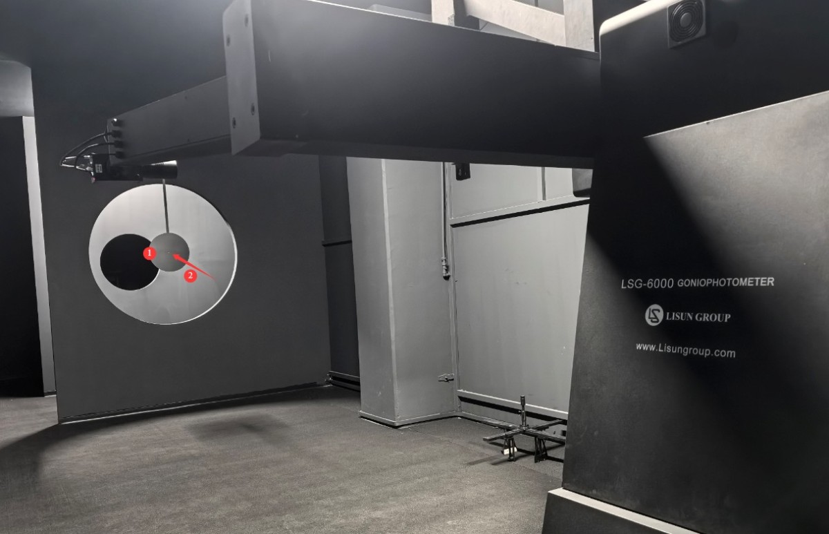
Gambar 87
Find the small cross-shaped laser shown below.
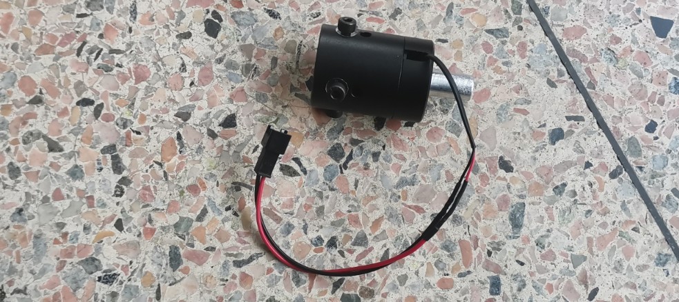
Gambar 88
| Jumlah | Note |
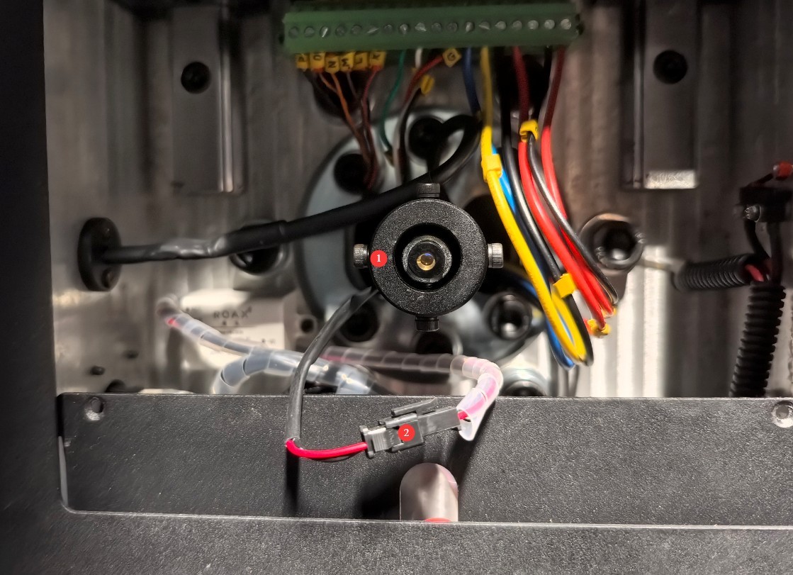
| ① | Remove the straight-line laser from the center of the treadmill and replace it with a small cross-shaped laser. |
| ② | After connecting the power cord, turn on the laser switch. Adjust the direction of the crosshair laser so that its center aligns with the mark you just made and the crosshair is perfectly level and plumb, then secure the small crosshair laser in place. |
Gambar 89
5.9 Equipment and Darkroom Cleaning
Once all installation and commissioning steps are complete, shut down all equipment. Note: The shutdown sequence is as follows: first, turn off the power to each piece of equipment one by one, and then turn off the main power switch for the cabinet.
After cleaning the equipment with a dry, soft cloth, reinstall all covers, screws, and other parts.
Then, cover all equipment with dust-proof cloths and clean the darkroom and control room. Once everything has been cleaned, turn on all the equipment.
6. Kalibrasi
6.1 Installation and Commissioning of Standard Lamps
6.1.1 Installation of Standard Lamps
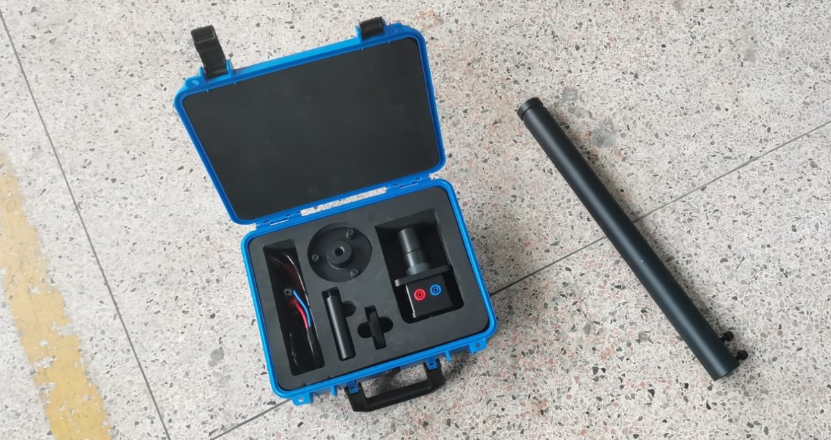
Find the standard lamp and its extension pole.
Gambar 90
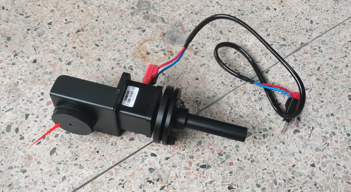
Assemble the standard lamp as shown in the figure below, and install the small mirror as well.
Gambar 91
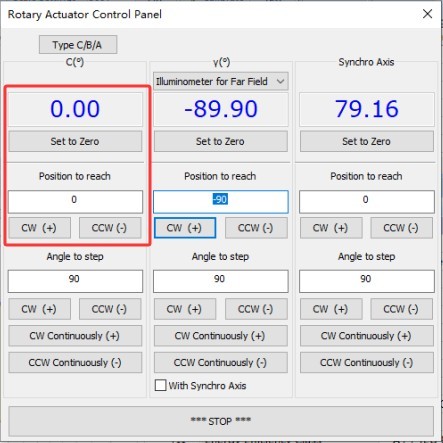
Go to the software angle control interface and rotate the C-axis to the 0-degree position.
Gambar 92
Attach the standard lamp to the extension rod, and then mount the extension rod to the lamp shaft.
| Jumlah | Note |
| ① | There is a slot on the extension rod. After removing the bolt from this slot, insert the extension rod all the way to the bottom and then loosen the bolt; this will lock it in place and prevent it from falling out. |
| ② | Turn the screw by hand; turning it counterclockwise loosens it, and turning it clockwise tightens it. |
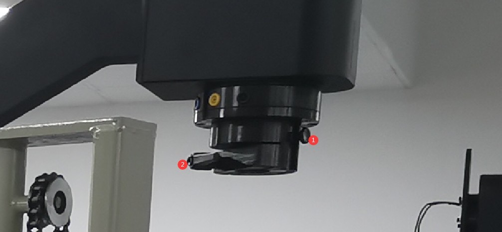
Gambar 93
Secure the standard lamp in the orientation shown in the figure below.
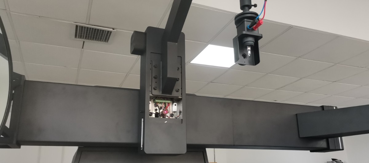
Gambar 94
There are four terminals on the light fixture. Please follow the diagram on the light fixture: short-circuit the red and yellow terminals together, and short-circuit the blue and black terminals together, then connect the red and blue wires to the standard light fixture power cord.
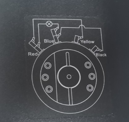
Gambar 95
Note: The connection method for the power supply of the standard lamp and the sample lamp is the same.
6.1.2 Adjusting the Orientation of the Standard Lamp
| Jumlah | Note |
| ① | Turn on the switch here |
| ② | Use the up/down switch to adjust the lamp shaft—that is, the height of the standard lamp. |
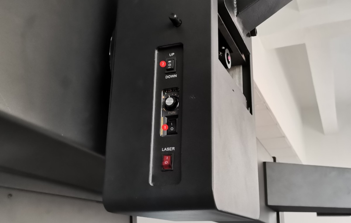
Gambar 96
The three screws on the standard lamp bracket allow you to adjust the pitch angle of the standard lamp.
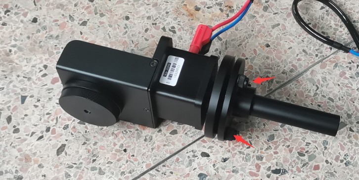
Gambar 97
The standard lamp should be adjusted so that the cross-shaped laser beam is directed at the center of the small mirror, and the horizontal and vertical laser beams reflected from the mirror coincide exactly with the original cross-shaped laser beam.
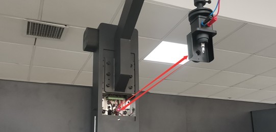
Gambar 98
Based on our experience, follow these steps for calibration: First, adjust the standard lamp to the appropriate height. The vertical reflected laser can be calibrated by rotating the extension rod, while the horizontal reflected laser can be calibrated by adjusting the standard lamp’s pitch. After calibration, the center height of the standard lamp may change, requiring you to readjust its height. Repeat this process until the crosshair laser is projected onto the center of the small mirror, and the reflected horizontal and vertical laser beams perfectly align with the original crosshair laser.
Once the standard lamp is properly aligned, carefully remove the small reflector, taking care not to alter the alignment of the standard lamp during removal. Then turn off the cross-hair laser.
6.2 Calibration of the Far-Field Photometric Probe
All standard lamps are constant-current DC light sources. Set the AC/DC switch on the 19-inch Standard Instrument Cabinet to DC.
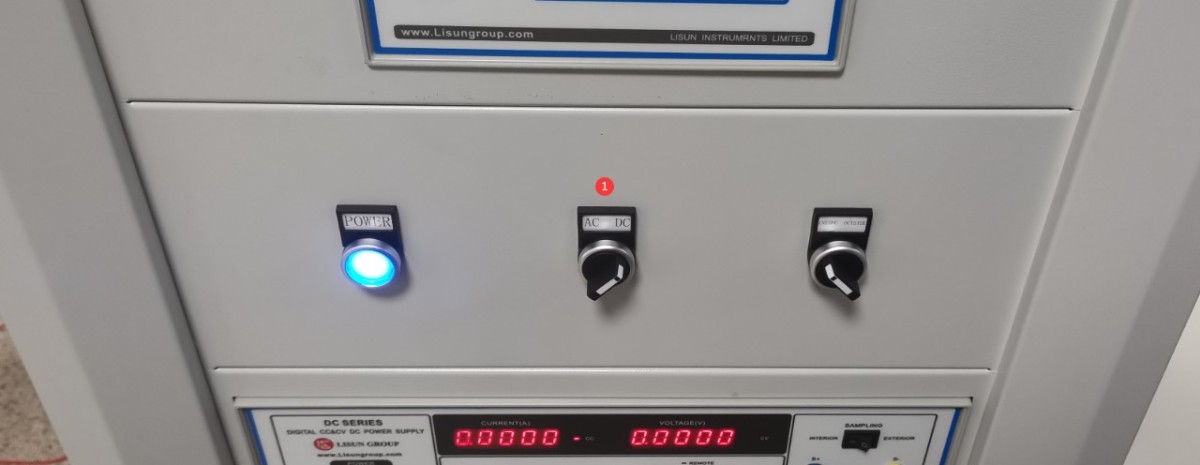
Gambar 99
Open the software’s angle control interface.
| Jumlah | Note |
| ① | Rotate the C-axis to the 90-degree position |
| ② | Be sure to check the “Synchronize Axes” box. |
| ③ | Then select the far-field photometer probe and rotate it to the 90-degree position. |
| ④ | The synchronizing shaft rotates in sync with the rearview mirror to the 90-degree position. |
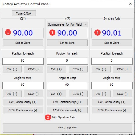
Gambar 100
Once you have moved to the target position, the round hole in the standard light bracket should be directly aligned with the rearview mirror.
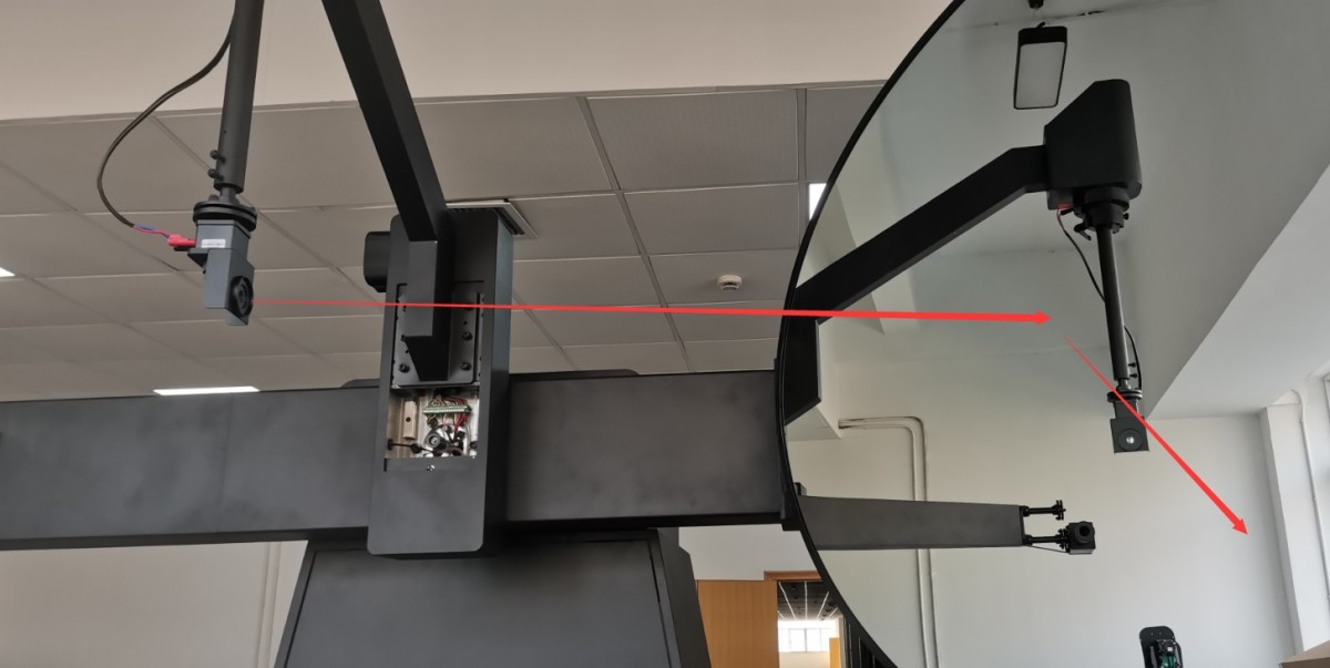
Gambar 101
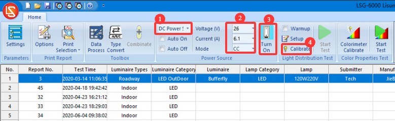
Turn on the calibration lamp and enter the calibration screen.
| Jumlah | Note |
| ① | Select a DC Power Supply |
| ② | The standard lamp is a constant-current light source. Select CC (constant-current mode) and enter the reference voltage and rated current as specified in the standard lamp certificate; these are typically 30 V and 6.1 A. |
| ③ | Click to turn on the standard lamp and turn off all other lights in the darkroom. The standard lamp takes 15 minutes to reach a steady state. |
| ④ | Once the standard lamp has stabilized, click to enter the photometer calibration interface. |
Gambar 102
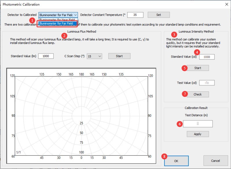
Close the darkroom door and make sure that all light sources in the darkroom are turned off, except for the standard lamp.
| Jumlah | Note |
| ① | Selecting a Far-Field Photometric Probe |
| ② | Luminous flux calibration—our software includes this option, but current standard practices require the use of luminous intensity calibration, and the standard lamps included in our standard configuration are also luminous intensity standard lamps. Therefore, there is no need to use luminous flux calibration at this time. |
| ③ | Light Intensity Calibration Method |
| ④ | Refer to the standard lamp calibration certificate and enter its calibrated luminous intensity value. |
| ⑤ | Klik untuk Memulai |
| ⑥ | The software will automatically calculate the test distance. |
| ⑦ | To verify the results, click “Check,” and the software will display the current measured light intensity value. The measured light intensity value should match the calibrated light intensity value. |
| ⑧ | Click “OK” to save and exit. |
Gambar 103
Note: The test distance for the far-field photometric probe is the distance from the center of the Goniophotomoeter to the reflector, plus the distance from the reflector to the surface of the far-field photometric probe. The distance calculated by the software should be close to the actual distance; an error of 1% or less is considered normal. If the error is too large, please refer to Section 2.3.1 to verify that the darkroom is functioning properly, and refer to Chapter 5 to review the calibration procedure.
6.3 Calibration of Near-Field Photometric Probes
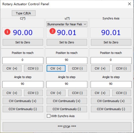
The reference lamp remains lit and stable. Enter the angle control interface.
| Jumlah | Note |
| ① | The C-axis is still at the 90-degree position |
| ② | Select the near-field photometer probe and rotate it to the 90-degree position . Note: When calibrating the near-field, you do not need to worry about the position of the synchronization axis. |
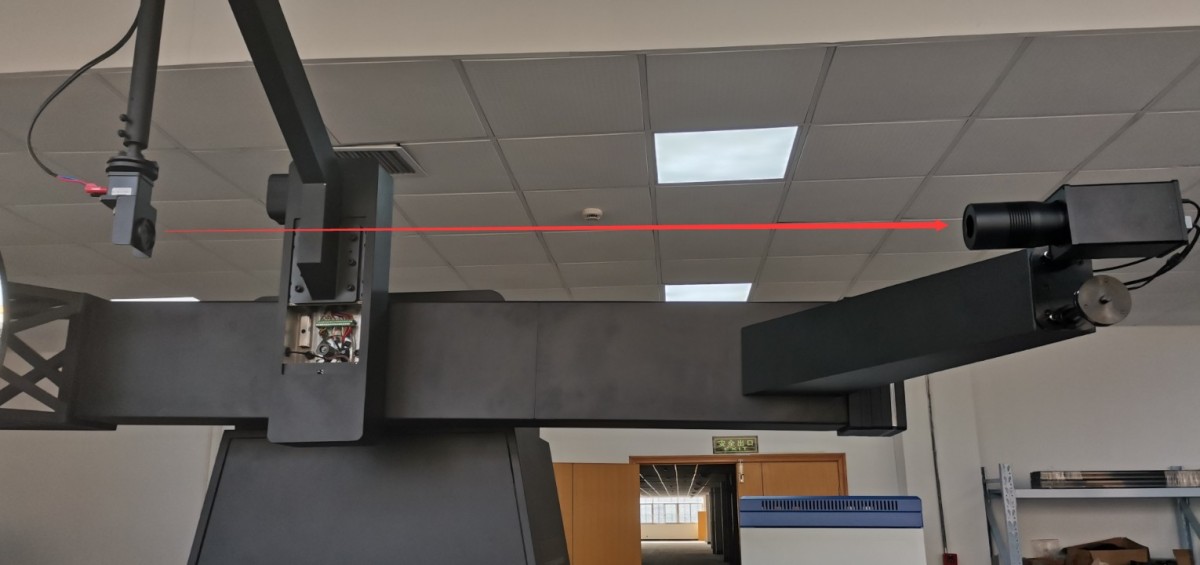
Gambar 104
Once the lamp has been rotated to the target position, the round hole in the standard lamp bracket is directly aligned with the near-field photometer probe.
Gambar 105
Go to the photometric probe calibration interface and select the near-field photometric probe. The remaining steps are exactly the same as those for calibrating the far-field photometric probe; please refer to Section 6.2.
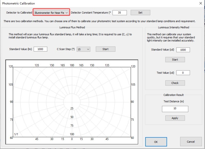
Gambar 106
Note: The standard distance for the LSG-6000S near-field photometric probe is 1.25 m, and the standard distance for the LSG-6000 near-field photometric probe is 1.5 m.while the standard measurement distance for the LSG-6000Pita LSG-6000L near-field photometric probes is 1.75 m.
6.4 Calibration of The Spectroradiometer (if applicable)
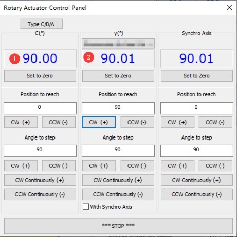
The reference lamp remains lit and stable. Enter the angle control interface.
| Jumlah | Note |
| ① | The C-axis is still at the 90-degree position |
| ② | Select the spectroradiometer and rotate it to the 90-degree position. |
Gambar 107
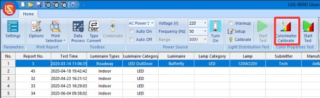
Once the device has been moved to the target position, the circular opening in the standard lamp mount should be aligned directly with the Optical Fiber path of the Spectroradiometer.
Click to open the Spectroradiometer calibration interface.
Gambar 108
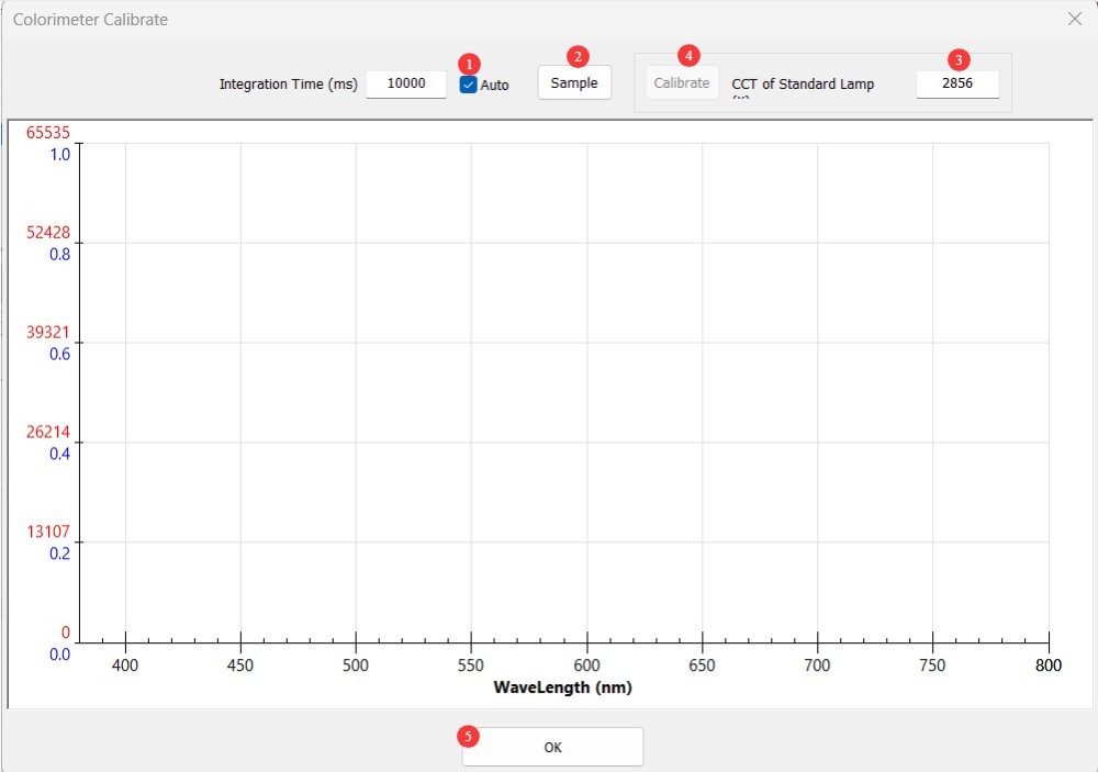
| Jumlah | Note |
| ① | For the points accumulation time, be sure to always select “Automatic.” |
| ② | First, click “Sampling.” Once sampling is complete, the corresponding curve will appear on the screen. After sampling is complete, the “Calibrate” button will become clickable. |
| ③ | Refer to the standard lamp calibration certificate and enter its calibrated color temperature value. |
| ④ | Click “Calibrate.” Once calibration is complete, the corresponding curve will appear on the screen. |
| ⑤ | Click OK to save and exit. |
Gambar 109
After calibration is complete, you can turn off the standard lamp using the software. Since the standard lamp becomes quite hot during use, wait for it to cool down before placing it back in its packaging and storing it safely along with the extension rod.
6.5 Kalibrasi dan Pemeliharaan
| No changes in the darkroom | If there have been no changes to the computer, recalibration is not necessary. |
| No changes were made to the computer; simply unplug and replug the communication cable or reinstall the Goniophotomoeter software—no need to recalibrate. | |
| If you replace your computer or reinstall the operating system, the photometric probe does not need to be recalibrated; simply enter the previous measurement distance and save it. However, the Spectroradiometer does need to be recalibrated (if you do not have the means to recalibrate it, please contact us to restore the calibration data). | |
| Changes in the Darkroom | The structure of the darkroom remains unchanged; however, after prolonged use, the interior paint may fade or peel. Depending on how well you maintain the darkroom and your requirements for the accuracy of test results, you may repaint the darkroom periodically. After repainting, the darkroom must be recalibrated. |
| There has been a change in the darkroom configuration, so recalibration is required. |
7. Persiapan Sebelum Pengujian
7.1 Lamp Selection and Aging
Select representative luminaires for testing that comply with national or corporate standards; new luminaires must undergo aging treatment (for LED luminaires, a 24-hour aging period is recommended);
Check that the light fixture has no visible damage, that the internal wiring is properly connected, and clean any stains from the surface of the fixture.
7.2 Introduction to Test Modes
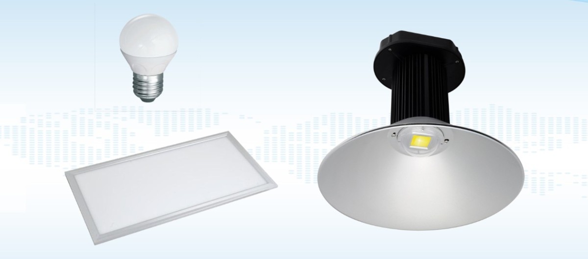
C-Gamma Mode: Suitable for most lighting fixtures, such as streetlights, downlights, panel lights, and plant grow lights.
Gambar 109.1
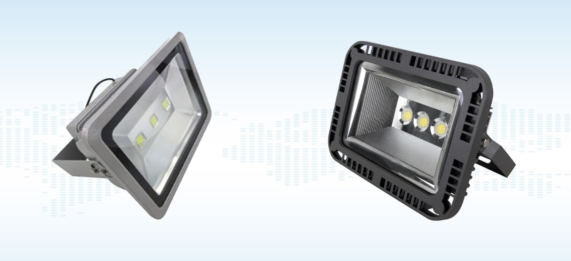
Beta Mode: Suitable for spotlights, floodlights, and similar fixtures; requires installation of an auxiliary arm.
Gambar 109.2
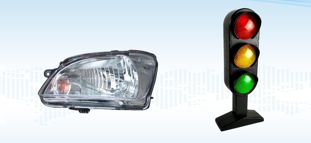
Alpha Mode: Suitable for automotive lights and signal lights.
Gambar 109.3
Catatan: LSG-6000 series can perform C-Gamma and B-Beta tests. For A-Alpha testing, a Type A Goniophotomoeter is required; please contact us if needed.
8. C-Gamma Test
8.1 Luminous Intensity Distribution Test
8.1.1 Installing and Turning On the Light Fixture
8.1.1.1 Pemasangan Perlengkapan Lampu
We have two C-Gamma test fixtures; this procedure uses the cross-shaped fixture as an example.
| Jumlah | Note |
| ① | Large cross-shaped clamps are used for various types of lighting fixtures |
| ② | E27 Fixture for Testing Globe Bulbs |
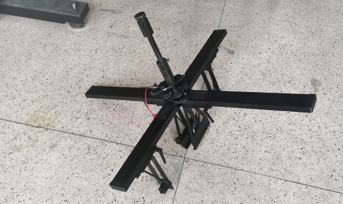
Gambar 110
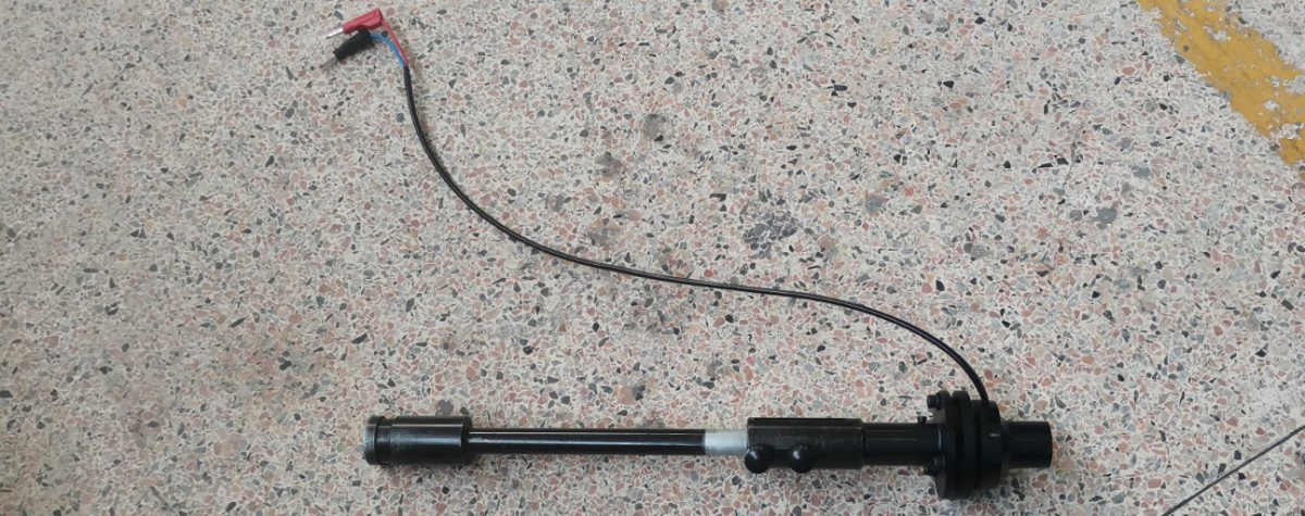
Gambar 111
Attach the fixture to the Goniophotomoeter using the same method as for installing the standard lamp extension rod.
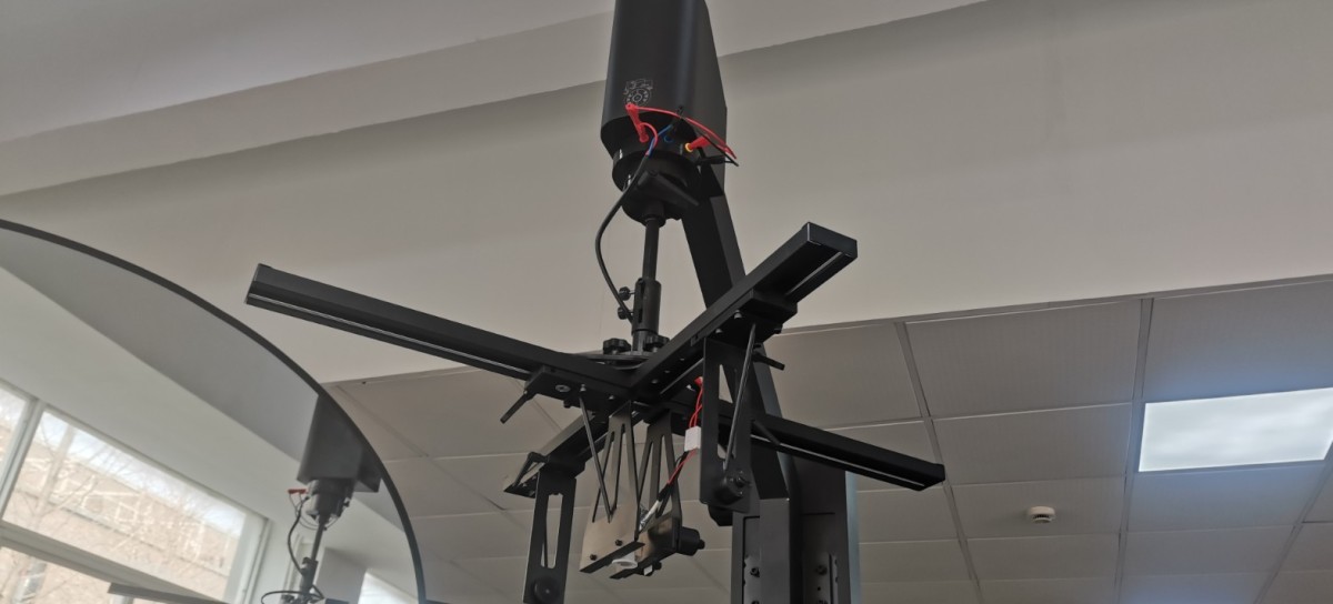
Gambar 112
Adjust the height of the light axis and the cross-shaped clamp so that the light-emitting surface of the sample is level with the cross-shaped laser.
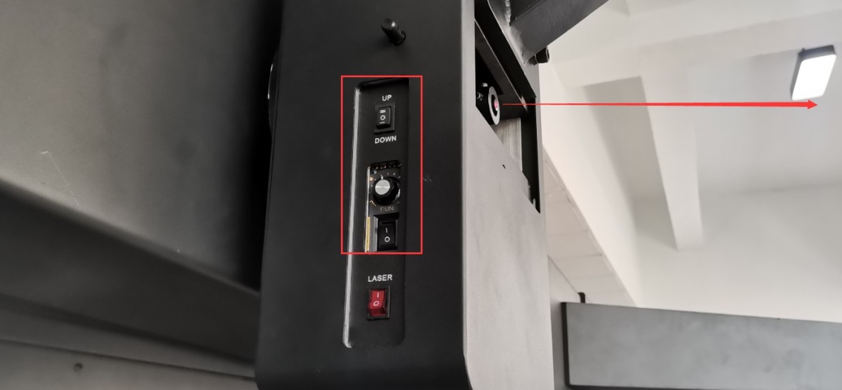
Gambar 113
Caution is required when installing directional luminaires. When the angle of the Goniophotomoeter’s C-plane is 0 degrees, according to streetlight installation standards, the light pole should face the Goniophotomoeter’s main unit; when the angle of the Goniophotomoeter’s C-plane is 0 degrees, according to industry standards for linear luminaires, the light pole should be perpendicular to the Goniophotomoeter’s main unit.
Once the light fixture is installed, you can turn off the crosshair laser.
8.1.1.2 Lighting the Lamps
Connect the power cord to the luminaire under test. The connection method for the luminaire under test is the same as that for the standard luminaire; refer to Section 6.1.1.
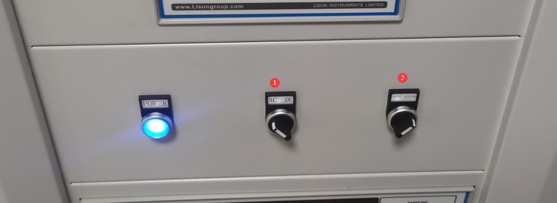
Adjust the cabinet switch according to the parameters of the luminaire being tested.
| Jumlah | Note |
| ① | If the sample luminaire is powered by AC, switch to the AC position; if it is powered by DC, switch to the DC position. |
| ② | Internal/External Sampling Switch for Electrical Parameters. External sampling uses a four-wire configuration, which provides more accurate voltage readings. Unless there are specific requirements, please set this switch to the external sampling position. |
Gambar 114
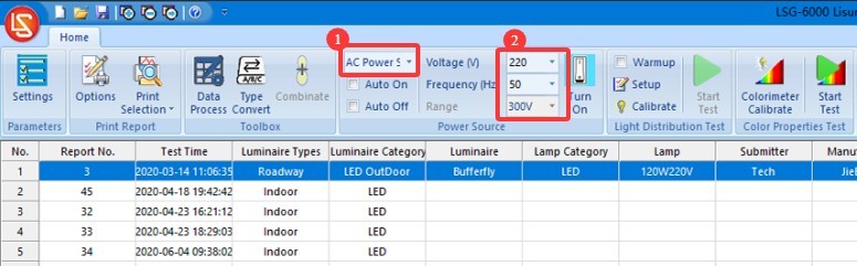
If the sample luminaire is AC-powered.
| Jumlah | Note |
| ① | Select AC Power |
| ② | Based on the sample parameters, enter the correct voltage and frequency. |
Gambar 115
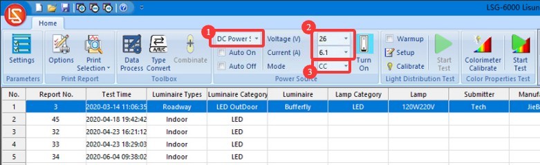
If the sample luminaire is DC-powered.
| Jumlah | Note |
| ① | Select a DC Power Supply |
| ② | Based on the sample parameters, enter the correct voltage and current. |
| ③ | Select the output mode: CC stands for constant current, and CV stands for constant voltage. If you select constant current, you need to enter the sample’s rated current value; for voltage, simply enter the maximum output voltage of this DC power supply. If you select constant voltage, enter the sample’s rated voltage; for the current value, simply enter the DC power supply’s maximum output current. Note: If your DC power supply model is DC3010Tegangan keluaran maksimumnya adalah 30 V dan arus keluaran maksimumnya adalah 10 A. |
Gambar 116
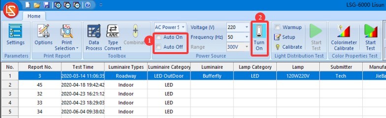
The software offers two methods for turning the sample lamp on and off, and users can choose either one.
| Jumlah | Note |
| ① | If you check the “Auto-On” and “Auto-Off” options, the software will automatically power on the sample according to the selected power source and the entered electrical parameters when the test begins, and will automatically cut off the sample’s power when the test ends. |
| ② | If the “Auto On” and “Auto Off” options are not checked, you can still click this button; the software will power on the sample based on the selected power source and the entered electrical parameters. Clicking this button again will cut off the power to the sample. |
Gambar 117
8.1.2 Pengaturan Parameter Pemanasan Awal
| Jumlah | Note |
| ① | If “Preheat” is checked, the software will preheat the luminaire according to the configured preheat parameters when the test begins, and the test will start automatically once preheating is complete. If “Preheat” is not checked, the software will begin the test immediately. |
| ② | Preheating Parameter Settings |
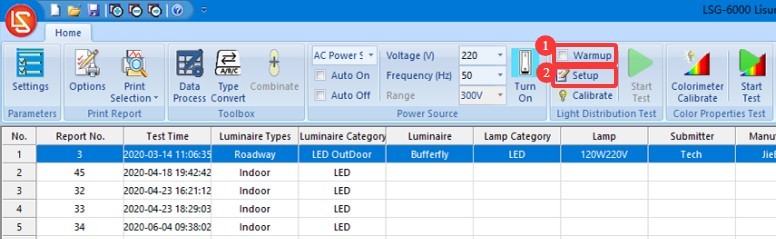
Gambar 118
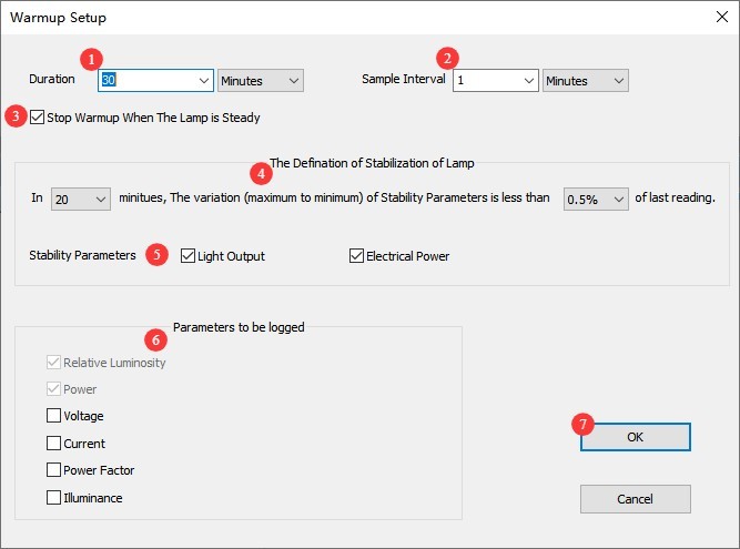
Click “Preheat Parameter Settings.”
| Jumlah | Note |
| ① | Warm-up Duration Setting: The purpose of the warm-up is to allow the light fixture to remain on for a period of time until its luminous and chromatic parameters stabilize, after which testing begins automatically. |
| ② | Sampling interval: The software will automatically take samples at the set interval throughout the entire warm-up period to obtain real-time data. We recommend setting the interval to 5 seconds or longer. |
| ③ | If checked, the test will automatically skip the remaining warm-up time and begin once the light fixture has stabilized; if unchecked, the warm-up will complete according to the set duration before the test begins. |
| ④ | Definition of a luminaire’s steady state. If the values are set to 20 and 0.5%, the luminaire is considered to be in a steady state if the variation in the parameter does not exceed 0.5% over the past 20 minutes. |
| ⑤ | Anda dapat memilih parameter mana yang harus digunakan perangkat lunak untuk menentukan apakah perlengkapan lampu stabil: parameter optik, parameter listrik. |
| ⑥ | The software will save the change curves for the selected parameters during the warm-up process in the test report. |
| ⑦ | Setelah Anda selesai mengkonfigurasi pengaturan, klik OK untuk menyimpan dan keluar. |
Gambar 119
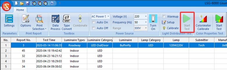
8.1.3 Configure Test Parameters and Start the Test
Click “Start Test.”
Gambar 120
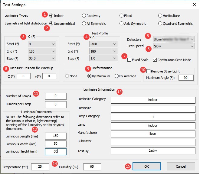
Buka layar pengaturan parameter pengujian.
| Jumlah | Note |
| ① | Lighting fixture types: indoor lights, outdoor lights, or plant grow lights—these three types of lighting fixtures are subject to C-Gamma testing. |
| ② | Select whether the luminaire is symmetrical. Unless there are specific requirements, select the first option, “asymmetrical,” regardless of whether the luminaire being tested is symmetrical or not (to obtain the luminaire’s actual data). |
| ③ | C-plane angle range: Select 0 to 180 degrees; no modification is needed. For data ranging from 180 to 360 degrees, the software will automatically convert the C-plane angle intervals. For symmetrical luminaires, such as indoor lights, you can select a larger interval, such as 30 degrees; for asymmetrical luminaires, such as streetlights, you can select a smaller interval, such as 10 degrees. The smaller the angle increment, the higher the testing accuracy, but the longer the testing time. If time permits, we recommend selecting a smaller angle increment. |
| ④ | Gamma plane angle range: If the sample’s light irradiation angle exceeds 180 degrees (e.g., incandescent bulbs), select -180 degrees to 180 degrees; if the sample’s light irradiation angle is less than 180 degrees (e.g., panel lights), you may select a Gamma plane angle increment of -90 degrees to 90 degrees. Unless there are special requirements, a 1-degree increment is sufficient. Different angle increments do not affect the test speed. |
| ⑤ | In the vast majority of cases, you should choose to use a far-field photometer. Near-field photometers are intended only for light sources with very low luminous intensity, such as a single LED. |
| ⑥ | For routine testing of standard lighting fixtures, select “Normal Speed”; if the lighting fixture being tested has an extremely narrow beam angle, select “Slow Speed” to obtain more accurate test results; for expedited testing, select “Fast Speed.” |
| ⑦ | Fixed Range: If you are consistently measuring the same type of light and the luminous intensity data does not vary significantly, you can check this box to save time. If you have ample time or frequently test lamps with varying luminous intensities, it is recommended that you leave this box unchecked. In this case, the photometric probe will automatically select the appropriate range for each lamp. Continuous Scan Mode is suitable when the angular interval on the Gamma plane is between -180 degrees and 180 degrees. During the test, when the Gamma angle approaches ±180 degrees, while simultaneously rotating the C-axis to the next scanning position—that is, the Gamma axis rotates continuously without stopping to save time. If you have ample time, we recommend leaving this option unchecked. |
| ⑧ | To set the monitoring angle during the lamp’s warm-up phase, simply set it to (0, 0). |
| ⑨ | Normalization refers to the decision of whether to apply a uniform value to the first row of data in the luminous intensity table of a test report; certain standards, such as the U. S. streetlight standard, may require you to perform a similar adjustment. There are three options: no normalization, normalization to the maximum value (which will slightly increase the luminaire’s total luminous flux), and normalization to the average value (which leaves the luminous flux essentially unchanged). |
| ⑩ | If you need to remove all stray light outside a specific angle, check this option and enter the desired angle . For example: If you check this option and enter 60, data outside ±60 degrees of the luminaire’s Gamma plane will automatically be set to 0. |
| ⑪ | Enter the number of light sources in the luminaire and the rated luminous flux of each light source. If you do not know this information, you may leave it blank; it will not affect the test results. |
| 1 | Enter the dimensions of the sample’s light-emitting surface. For indoor lighting fixtures, the software requires this data to calculate the luminance limit curve, UGR, and other parameters. |
| ⑬ | Enter information about the sample luminaire |
| ⑭ | The software automatically reads the temperature and humidity data from the host’s thermometer and hygrometer. |
| 3 | Click OK to go to the warm-up screen, or go to the test screen. |
Gambar 121
Then wait for the software test to finish. Once the test is complete, refer to Section 8.2 to perform the chromaticity distribution test.
8.2 Chromaticity Distribution Test
After completing the C-Gamma luminous intensity distribution test, a chromaticity distribution test can be conducted based on the test report.
Note: The software must automatically calculate the spatial angle range required for the chromaticity distribution test based on the photometric distribution test report. Therefore, if a photometric distribution test is not performed, a chromaticity distribution test cannot be conducted directly.
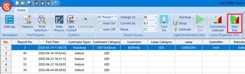
Select the photometric distribution test report for this luminaire, then click to open the chromaticity distribution test parameter settings interface.
Gambar 122
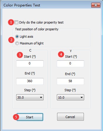
| Jumlah | Note |
| ① | If checked, only the chromaticity characteristics test will be performed; the chromaticity distribution test will not be performed. If unchecked, both the chromaticity characteristics test and the chromaticity distribution test will be performed. |
| ② | Selection of test positions for colorimetric characteristics. The “optical axis” refers to the position directly in front of the light-emitting surface of the sample luminaire; the “point of maximum luminous intensity” refers to the position where the luminous intensity of the sample luminaire is greatest. |
| ③ | The angle range for the C-plane is 0 to 360 degrees. There is no need to adjust the angle increment for the C-plane. Symmetrical fixtures, such as indoor lights, can use a larger increment—for example, 30 degrees—while asymmetrical fixtures, such as streetlights, can use a smaller increment—for example, 10 degrees. The smaller the increment, the higher the test accuracy, but the longer the test takes. |
| ④ | The gamma plane angle range is automatically calculated by the software based on the results of the photometric distribution test. There is no need to adjust the angle intervals of the gamma plane. You may also select a larger angle interval; symmetrical luminaires, such as indoor lights, can use a larger interval—for example, 10 degrees—while asymmetrical luminaires, such as streetlights, can use a smaller interval—for example, 5 degrees. The smaller the angle interval, the higher the test accuracy; however, the test will take longer. |
| ⑤ | Once you’ve finished setting it up, click “Start” to begin the test, and wait for the software to automatically complete the self-test. |
Gambar 123
9. B-Beta Testing
9.1 Luminous Intensity Distribution Test
9.1.1 Installing and Turning On the Lights
9.1.1.1 Pemasangan Perlengkapan Lampu
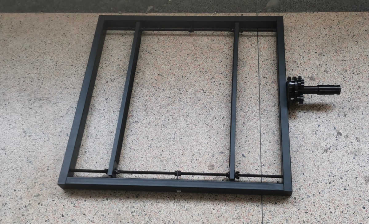
Find the Square B-Beta Test Fixture.
Gambar 124
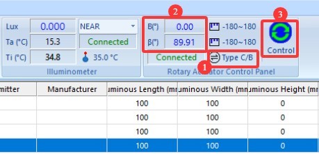
| Jumlah | Note |
| ① | Click to switch the viewing angle |
| ② | Click ① to display the B-Beta angle here instead of the C-Gamma angle. |
| ③ | Click to open the angle control interface |
Gambar 125
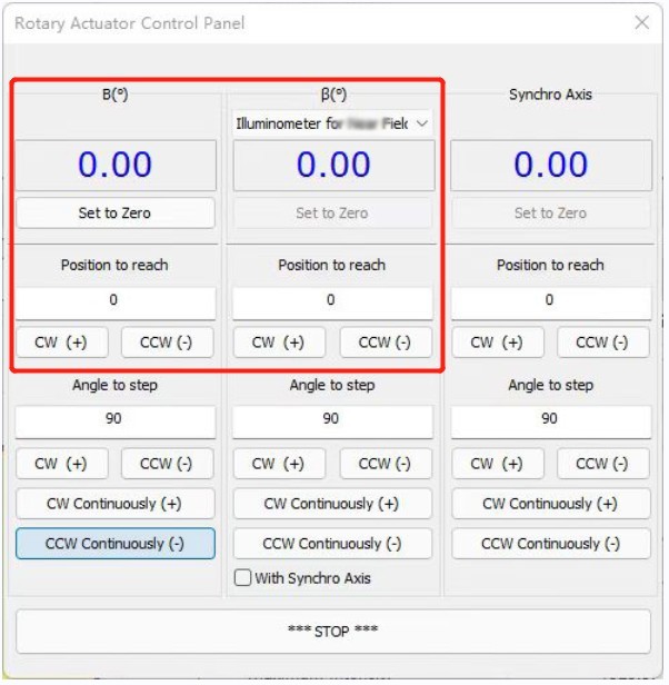
Similarly, in the vast majority of cases, you should choose to use a far-field photometer. Select the far-field photometer and set both the B and Beta angles to 0 degrees.
Gambar 126
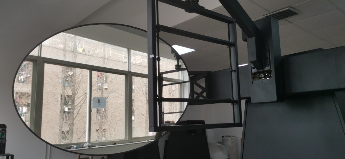
Install and secure the B-Beta fixture to the lamp shaft as shown in the figure below, and secure the sample to the fixture. When using a far-field photometric probe, install the lamp so that its light-emitting surface faces the reflector (Note: When using a near-field photometric probe, install the lamp so that its light-emitting surface faces the near-field photometric probe). To ensure the lamp’s light-emitting surface is centered, set the B angle to 90 degrees in the software and align the lamp’s light-emitting surface with the central crosshair laser on the main unit to verify proper positioning.
Gambar 127
Once the light fixture is installed, you can turn off the cross-line laser.
9.1.1.2 Turning on the Lights
Please refer to 8.1.1.2.
9.1.2 Pengaturan Parameter Pemanasan Awal
Please refer to 8.1.2.
9.1.3 Configure Test Parameters and Start the Test
Click “Start Test” to go to the test parameter settings screen.
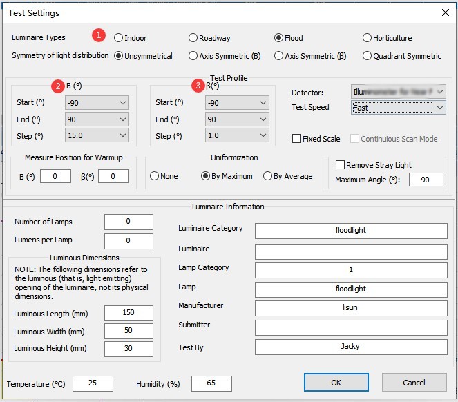
| Jumlah | Note |
| ① | Please select “Floodlight,” and the test mode will automatically switch to B-Beta. |
| ② | The angle range for Plane B is -90 degrees to 90 degrees. There is no need to adjust the angle increments for Plane B; you can select smaller increments, such as 5 degrees or 10 degrees. The smaller the increment, the higher the test accuracy, but the longer it takes. |
| ③ | The Beta plane angle range is -90 degrees to 90 degrees. There is no need to adjust the Beta plane angle increment; unless there are special requirements, select 1 degree. Different angle increments here have no effect on test speed. |
Gambar 128
For other parameter settings, refer to Section 8.1.3. Once the settings are configured, click “Start” and wait for the software to complete the test. After the test is complete, refer to Section 9.2 to perform a chromaticity distribution test.
9.2 Chromaticity Distribution Test
After completing the B-Beta luminous intensity distribution test, a chromaticity distribution test can be conducted based on the test report.
Select the photometric distribution test report for this luminaire, then click to open the chromaticity distribution test parameter settings screen.
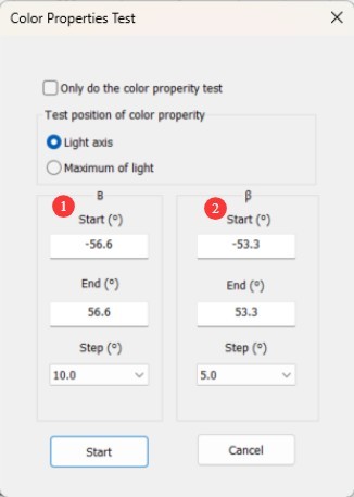
| Jumlah | Note |
| ① | The angle range for Plane B is automatically calculated by the software based on the results of the photometric distribution test; there is no need to adjust the angle intervals for Plane B. Options include 5 degrees and 10 degrees, for example. The smaller the interval, the higher the test accuracy, but the longer it takes. |
| ② | The beta-plane angle range is automatically calculated by the software based on the results of the photometric distribution test; there is no need to adjust the beta-plane angle intervals, which can be set to values such as 5 degrees or 10 degrees. The smaller the interval, the higher the test accuracy, but the longer the test takes. |
Gambar 129
For other parameter settings, please refer to Section 8.2. Once you have configured the settings, click “Start” and wait for the software to automatically complete the test.
10. Processing of Test Reports
10.1 Organizing Database Files
| Jumlah | Note |
| ① | By default, all test reports are automatically stored in the currently open database file in the order in which the tests were run. |
| ② | To delete a report, select it and then click “Delete.” |
| ③ | To make it easier to find test reports, click the blank button shown in the image below to create a new database file, and store reports for different lighting fixtures in separate database files. After creating a new database file, you can proceed directly with testing without needing to recalibrate or reconfigure the system. |
| ④ | Click “Open” to view test reports from other database files. |
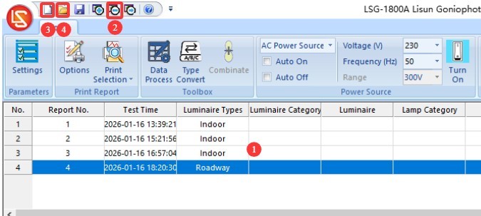
Gambar 130
Note 1: The next time the software is opened, it will automatically load the database file used last time. If the path to that database file has changed or its name has been modified, the software will prompt you to create a new database file.
Note 2: Avoid placing database files on your computer’s desktop whenever possible.
10.2 Test Report Display Settings
| Jumlah | Note |
| ① | You can double-click to upload a picture of the light fixture. |
| ② | You can double-click the content displayed in this area to edit it. |
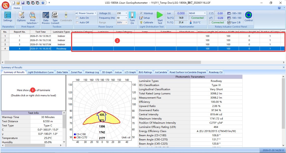
Gambar 131
| Jumlah | Note |
| ① | Klik "Pengaturan" |
| ② | For unit selection, “cd” is generally used; however, some older standards—such as those regarding energy-saving light bulbs—may require the use of “cd/klm.” |
| ③ | Streetlight C0 angle setting. The CIE/GB and IESNA standards have inconsistent requirements; please select the standard you are following. |
| ④ | Customize the divergence angle. The software automatically displays the half-peak angle (commonly referred to as the beam angle, calculated as 50% of the maximum luminous intensity) and the effective beam angle (calculated as 10% of the maximum luminous intensity). If you wish to customize the divergence angle, enter the percentage of the maximum light intensity and check the box (e.g., 0.25 for 25%). In this case, the test report will display not only the half-peak angle and effective beam angle but also your custom divergence angle. |
| ⑤ | Check this box to display the maximum luminous intensity cone angle in the report. |
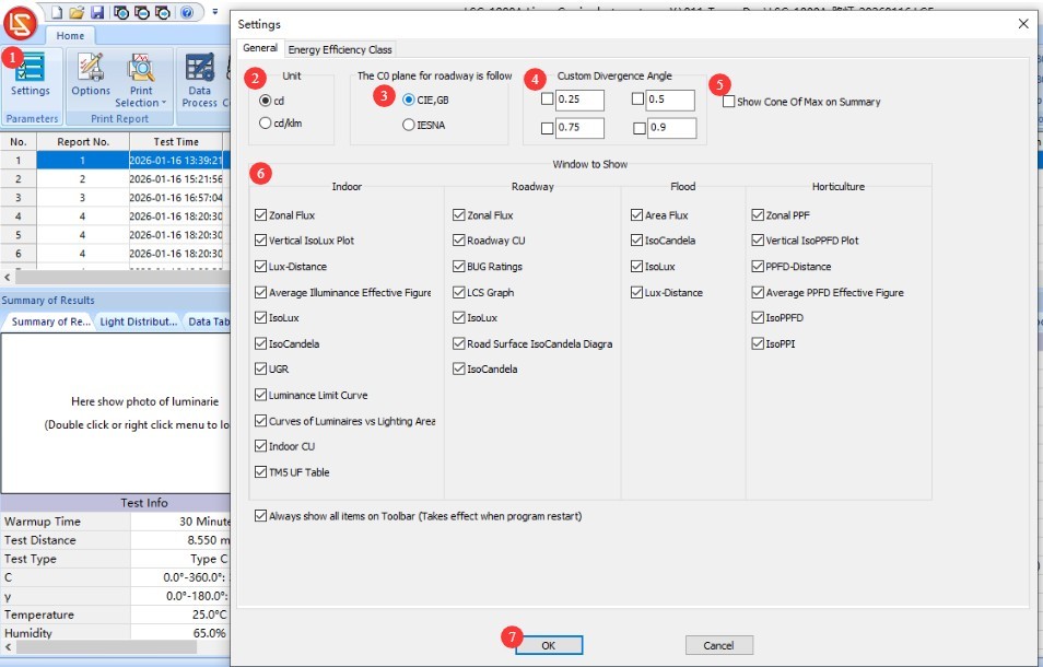
Gambar 132
| Jumlah | Note |
| ① | Switch to the “Energy Efficiency Rating” settings screen, then select the applicable standard and luminaire type. |
| ② | Click to apply to the current test report |
| ③ | Click OK to save and exit |
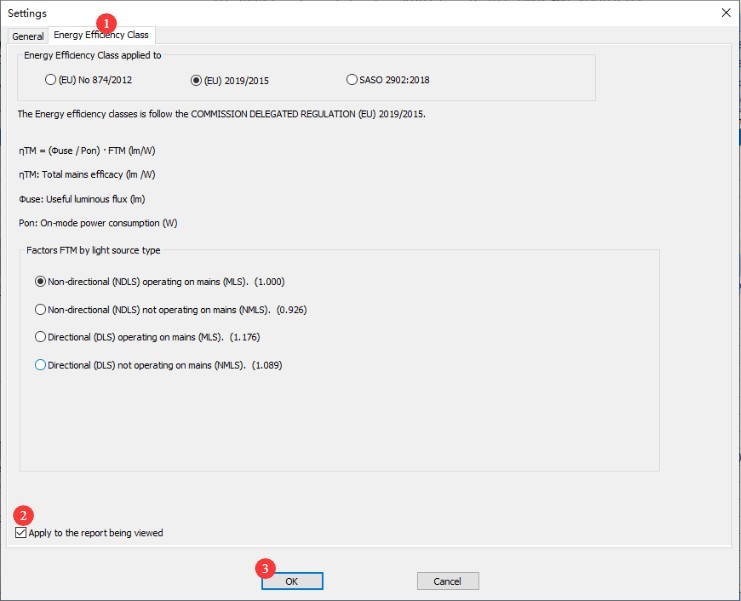
Gambar 133
Each display window has several settings that allow you to customize the display. Users can experiment with adjusting these settings to achieve the desired display effects.
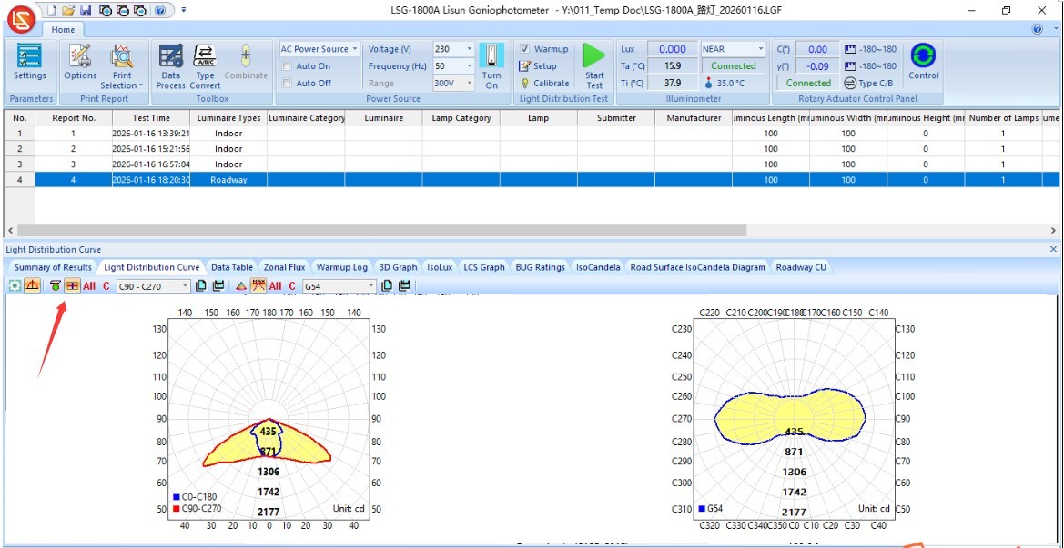
Gambar 134
10.3 Processing Test Data
10.3.1 Double-Sided Light Fixtures
For lamps that emit light from both sides, please use the indoor lighting test mode to test each side individually—that is, set the gamma plane angle range to -90 degrees to 90 degrees during testing—and then generate two test reports.
| Jumlah | Note |
| ① | Hold down the “Ctrl” key on your computer keyboard, then click to select the two test reports you just received. |
| ② | Click “Data Synthesis” in the software navigation bar |
| ③ | In the pop-up window, you can click to toggle between the upward and downward light beams. |
| ④ | Select “Composite” |
| ⑤ | Click OK to save and exit |
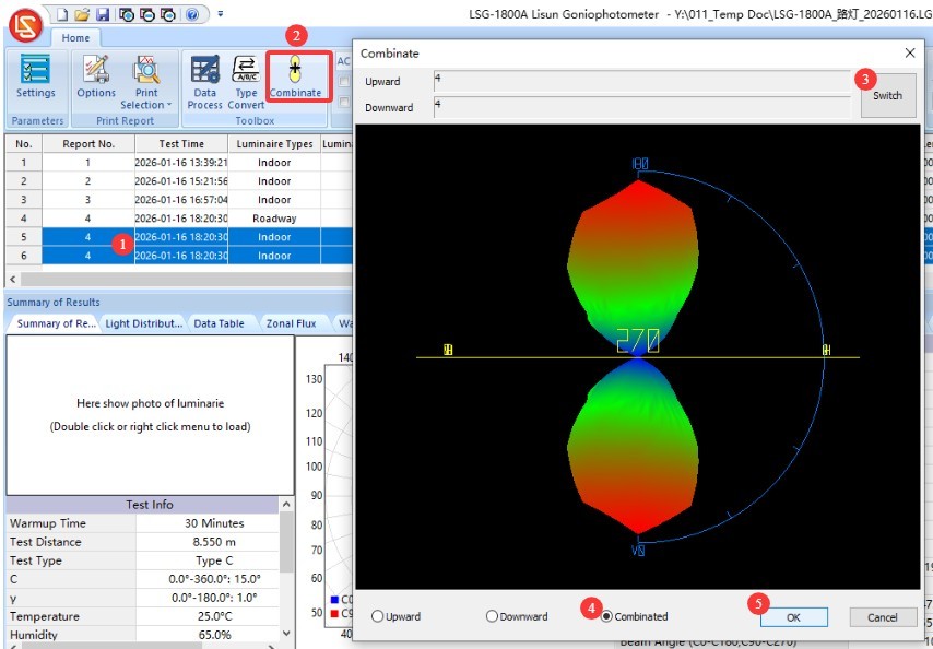
Gambar 135
This will generate a new synthetic test report, as shown in the figure below.
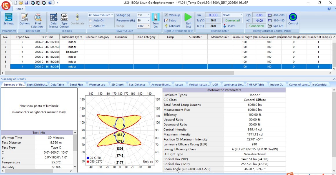
Gambar 136
10.3.2 Conversion of Test Report Types
| Jumlah | Note |
| ① | Click “Type Conversion” |
| ② | Test reports can be converted among four types |
| ③ | When converting to a C-Gamma test report, you can use the “termination angle” of the C-plane to generate a symmetric test report. If the termination angle is set to 360 degrees, there will be no symmetry; if the termination angle is set to 180 degrees, the report can be converted into an axisymmetric test report; if the termination angle is set to 90 degrees, the report can be converted into a quadrant-symmetric test report; if the termination angle is set to 0 degrees, the report can be converted into a fully symmetric test report. This feature is primarily intended for symmetric indoor lighting fixtures; certain lighting design software programs, such as DIALUX, may require you to use it when importing fully symmetric IES files. |
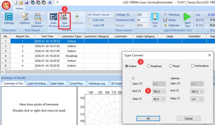
Gambar 137
10.4 Exporting Test Data and Printing Test Reports
10.4.1 Exporting Test Data
| Jumlah | Note |
| ① | Click the red logo in the upper-left corner of the software |
| ② | Click “Export Data” in the drop-down menu |
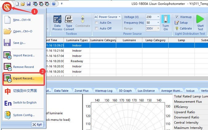
Gambar 138
Files can be exported in a variety of standard formats.
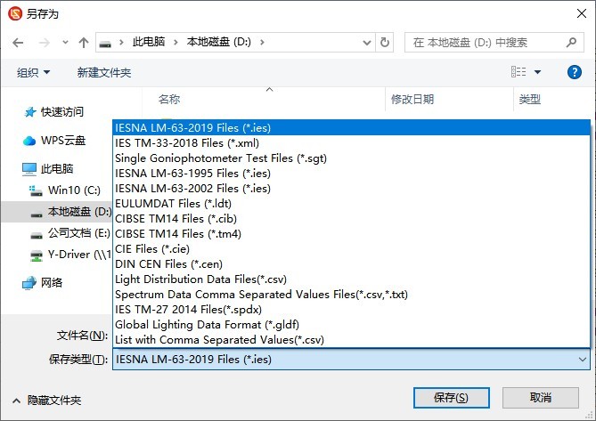
Gambar 139
10.4.2 Printing Test Reports
Print settings.
| Jumlah | Note |
| ① | Click to open the “Print Settings” screen |
| ② | The report displays language options; you can choose between Chinese and English. |
| ③ | Format Nomor Halaman |
| ④ | Report Header Information |
| ⑤ | Report Titles in Chinese and English |
| ⑥ | General Report Content, Applicable to Reports for All Types of Lighting Fixtures |
| ⑦ | Since indoor lights, streetlights, floodlights, and plant grow lights have different key parameters, the report content will vary accordingly. You can select the specific items you want to include in the report. |
| ⑧ | TM-30 Options |
| ⑨ | CIE color space diagram or SDCM color tolerance diagram—only one of the two may be selected |
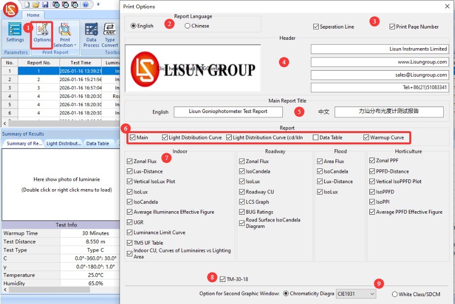
Gambar 140
| Jumlah | Note |
| ① | Click to print the currently selected test report |
| ② | Click to print all test reports in the current database file. |
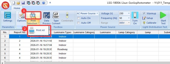
Gambar 141
11. Pemeliharaan dan Perawatan Peralatan Harian
11.1 Perawatan Rutin
Start-up procedure: First, turn on the main power switch for the cabinet. Next, turn on the power switches for the equipment inside the cabinet and in the darkroom one by one. Finally, launch the software. Shutdown procedure: First, close the software. Next, turn off the power switches for the equipment inside the cabinet and in the darkroom one by one. Finally, turn off the main power switch for the cabinet.
Keep the darkroom control room clean and dust-free to prevent dust from entering the equipment. If there is dust on the surface of the equipment, wipe it off with a dry, soft cloth.
Avoid exposing the darkroom to high humidity for extended periods; keep a dehumidifier on hand if necessary.
11.2 Pemeliharaan Reguler
11.2.1 Standard Lamp
The standard lamp is valid for one year. If you still need to calibrate the darkroom after one year, we recommend purchasing a new standard lamp.
Perangkat Lunak 11.2.2
We update the software from time to time to add features and fix bugs. If you encounter any issues while using the software, please feel free to contact us at any time to obtain the latest version.
11.3 Penonaktifan dan Pemeliharaan Jangka Panjang
11.3.1 Equipment Cleaning and Protection
Thoroughly clean all equipment surfaces, and cover the main unit, photometric probe, Optical Fibre, and cabinet with dust-proof cloths; disconnect all power sources and unplug power cords and communication cables.
11.3.2 Perlindungan Lingkungan
Ensure that the darkroom is dry and well-ventilated to prevent equipment from becoming damp. If the ambient humidity is high, keep a dehumidifier on hand.
11.3.3 Monthly Power-On
Lakukan uji penyalaan daya sebulan sekali untuk memastikan semua perangkat keras sistem berfungsi dengan baik.
12. Pemecahan Masalah dan Penyelesaian Masalah Umum
12.1 Kesalahan Komunikasi
Cause of the problem: Check that the communication cable is securely connected and that it is plugged into the correct port; verify that the drivers are installed correctly; try a different USB port or communication cable to rule out hardware issues.
Solution: Reinstall the driver, connect the communication cable according to the device identifier, restart the software, and try again.
12.2 Kesalahan Pengujian
12.2.1 Luminous Flux Anomalies
Cause of the malfunction: Check whether the light source is stable and whether the warm-up time is sufficient; verify that the equipment calibration is valid, that the test distance is correct, and that the standard light is functioning properly; check whether there is any external light interference in the darkroom and whether the light path is obstructed.
Solution: Extend the warm-up time, recalibrate the instrument, turn off other light sources in the darkroom, and remove any obstructions from the light path.
12.2.2 UGR Anomalies
Cause of error: Dimensions of the luminaire’s light-emitting surface were not entered; the luminaire’s beam angle is <45°; the calculation standard was selected incorrectly.
Solution: Enter the dimensions of the luminaire’s light-emitting surface (length/width/height) correctly; verify that the luminaire is an indoor luminaire (the beam angle must be sufficient); select the CIE 190:2010 standard and recalculate.
12.2.3 Abnormal Chromaticity Distribution Test Results
Cause of the malfunction: The test was not conducted based on the photometric distribution test report for the current luminaire; the light intensity was too low, preventing the Spectroradiometer from accurately measuring the colorimetric parameters.
Procedure: Please first conduct a luminous intensity distribution test, and then perform a color distribution test based on that report; if the luminaire’s luminous intensity is too low, please contact us for the best solution.
12.3 The Goniophotomoeter Does Not Rotate
Cause of the malfunction: Check whether the host power is on and whether the wiring is correct; check whether the angle controller inside the cabinet is functioning properly; confirm whether any foreign objects are jammed in the rotating shaft.
Solution: Check the power supply and wiring, and remove any foreign objects; restart the device and software, then try again.
12.4 Software Failures
12.4.1 Kerusakan Perangkat Lunak
Cause of the problem: Check whether you are logged in to the computer’s operating system with an administrator account; verify that the software is fully installed; check whether the database files are corrupted.
Solution: Log in to the computer using an administrator account; reinstall the software and drivers; create a new database file.
12.4.2 The software displays the message “File is not a database”
Cause of the problem: The database file was deleted or moved; the default program used to open LGF files was changed.
Solution: Create a new database file and save it; restore the default program for opening LGF files.
12.5 Kegagalan Daya
12.5.1 DC Power Output Abnormalities
Causes of the malfunction: The AC/DC switch on the cabinet was not set to DC; the sample voltage or current exceeded the DC power supply limits; a short circuit in the sample;
Troubleshooting: Please verify that the sample’s voltage and current are within the DC power supply’s output range. For example, the DC3005 Model ini memiliki tegangan keluaran maksimum 30 V dan arus keluaran maksimum 5 A. Periksa apakah sampel mengalami korsleting; jika ya, perbaiki sampel sebelum melakukan pengujian ulang.
12.5.2 No AC Output
Cause of the malfunction: The AC/DC switch in the cabinet was not set to the AC side; the overload protection was triggered;
Troubleshooting Steps: Check the AC power output wiring and sample connections to ensure there are no loose connections or short circuits; if the overload protection is triggered, turn off the power, let the unit cool for 5 minutes, and then restart it. Ensure that the sample power remains within the AC power output range; for example, the LSP-500VARC has a maximum output power of 500W.