
 Inggris
 中文简体
中文简体 Русский
 Español
 Português
 Türkçe
 العربية
 Deutsch
 Polski
 Italiano
 Français
 한국어
한국어 ไทย
ไทย Tiếng Việt
 日本語
日本語





























Rotasi Presisi Tinggi Luminer Goniospectroradiometer
Pengguna manual
berlaku LISUN Model: LSG-1800ACCD
1. Membuka Kemasan dan Mengenal Peralatan Secara Dasar
1.1 Membuka Kemasan dan Pemeriksaan
Saat membuka kemasan perangkat, tangani dengan hati-hati untuk menghindari goresan pada casing dengan alat tajam. Setelah membuka kemasan, periksa terlebih dahulu bagian luar perangkat untuk memastikan tidak ada deformasi atau penyok yang terlihat, dan tombol-tombolnya tidak rusak atau longgar. Jika Anda melihat kelainan pada perangkat atau aksesorinya, jangan menyalakannya. Segera hubungi kami.
1.2 Konfigurasi dan Gambaran Umum Sistem
1.2.1 Komponen Perangkat Keras Inti
Catatan: Tabel di bawah ini mencantumkan komponen perangkat keras inti dari keseluruhan sistem. Peralatan yang Anda beli mungkin hanya mencakup beberapa komponen ini; harap perhatikan hal ini saat mengikuti petunjuk dalam manual ini.
| Nama komponen | Model/Spesifikasi | Fitur Inti |
| Unit Utama Goniophotometer | LSG-1800A | Used in conjunction with photometric probes and Spectroradiometers to measure photometric parameters and their spatial distribution, as well as colorimetric parameters and their spatial distribution. |
| Spectroradiometer | LMS-9000CG | Used to test colorimetric parameters and their spatial distribution, such as color temperature and spatial color distribution |
| Probe fotometri medan dekat | PM400C (Utara) | Suitable for standard darkrooms, such as those around 10 meters in size |
| Probe fotometri medan jauh | PM400C (F) | Optional. Suitable for extra-long darkrooms, such as those longer than 20 meters. |
| Lampu Standar | SLS-150W | Digunakan untuk mengkalibrasi ruang gelap; termasuk probe fotometrik dan spektrofotometer. |
| Perlengkapan E27 | / | Untuk pengujian C-Gamma; cocok untuk lampu pijar. |
| Penjepit Silang | Untuk pengujian C-Gamma; cocok untuk perlengkapan pencahayaan dalam dan luar ruangan lainnya. | |
| Penjepit Persegi | Untuk pengujian B-Beta; cocok untuk lampu sorot | |
| Laser Garis Silang | Digunakan selama instalasi dan pengoperasian awal; digunakan selama kalibrasi dan pengujian untuk menentukan posisi dan orientasi lampu standar dan luminer sampel. | |
| Kabinet | CASE-19 | Used to house angle controllers, power meters, and DC and AC power supplies. Includes a power strip, an RS-485 communication module, and more. |
| Pengukur daya | Seri LS | Measure electrical parameters such as voltage, current, power, and power factor of the sample |
| DC Power Supply | Seri DC | Menyediakan catu daya DC yang stabil untuk sampel DC, lampu standar, dan lampu bantu. |
| AC Power | Seri LSP | Provides a stable, pure sine-wave AC power supply for AC samples |
1.2.2 Perangkat lunak, manual, sertifikat, dll.
At the time of shipment, a download link containing all the documents was sent via email. Please download them as soon as possible. If you missed the email, you can also contact us directly to request a new download link.
Termasuk perangkat lunak, buku panduan pengguna, kartu garansi, sertifikat kalibrasi lampu standar, dan dokumen penting lainnya, serta dokumen relevan lainnya.
1.3 Parameter Pengukuran
Illuminance data, illuminance distribution, area luminous flux, luminaire efficiency, luminance distribution (optional), utilization factor, luminance limit curve, glare rating, isophote curves, maximum allowable height-to-distance ratio, luminaire curve vs. illumination area, isointensity curves, effective beam angle, EEI, UGR, CCT, CRI, TM-30-24, Spectrum, (x, y)/(u, v), PAR, PPF, and PPFD spatial distribution testing, etc.
2. Catatan Penting
2.1 Keamanan Listrik
Sistem harus dihubungkan ke sumber daya AC stabil 220 V ±5%, dengan frekuensi 50 Hz atau 60 Hz. Pastikan pentanahan yang tepat, dengan resistansi pentanahan ≤4 Ω. Jangan gunakan peralatan jika sambungan daya longgar atau kabel rusak.
2.2 Keselamatan Lingkungan
When using the optical darkroom, the ambient temperature must be maintained at 25±1°C, and the relative humidity must be maintained between 10% and 65% RH;
Both the control room and the darkroom must be kept dry, well-ventilated, dust-free, and free of corrosive gases;
Avoid placing the device near strong magnetic or electric fields; it must be placed on a flat, sturdy surface.
2.3 Prosedur Operasi Ruang Gelap
2.3.1 Deskripsi Ruang Gelap
Please confirm that the darkroom has been constructed exactly according to the darkroom drawings we provided. If there are any discrepancies in the actual dimensions, please notify us before installing and commissioning the equipment so that we can adjust the plan to ensure that installation and commissioning proceed smoothly and that test results are accurate;
The interior of the darkroom must be completely painted matte black—that is, a non-reflective pure black—including all walls, ceilings, floors, partitions, doors, and so on. A small number of components, such as lights, air conditioning units, and power switches, may not be painted black, provided they do not appear in the optical path between the Goniophotomoeter’s main unit and the photometric probe;
Once the equipment has been installed and commissioned, do not move any of the hardware components inside the darkroom, including the main unit base, the photometer probe base, the photometer probe orientation, and the cross-laser base; doing so may result in inaccurate test results.
2.3.2 Precautions for Using the Darkroom
Lepaskan sepatu Anda atau kenakan penutup sepatu saat memasuki ruang gelap untuk mencegah debu masuk;
Luminer sampel harus dipasang dengan aman untuk mencegahnya jatuh dan merusak Goniophotometer selama pengujian;
Do not place any objects on the main unit of the Goniophotomoeter, and do not place any objects within the Goniophotomoeter’s rotation range;
During testing, the darkroom must remain sealed to prevent external light from interfering with the test results.
2.3.3 Precautions When the Darkroom Is Not in Use
Keep the darkroom closed; unauthorized persons are not allowed to enter; prevent dust from entering the darkroom.
2.4 Prosedur Pengoperasian Lampu Standar
The standard lamp has a lifespan of one year and is used for calibrating darkroom equipment (photometric probes, spectrometers) during installation and commissioning;
Jika laboratorium Anda diharuskan untuk mengkalibrasi ruang gelapnya setiap tahun, Anda dapat membeli lampu standar baru;
Lampu standar akan terasa panas segera setelah digunakan; jangan disentuh. Biarkan dingin selama 10 menit sebelum mengembalikannya ke wadah lampu;
The standard lamp used in the darkroom is a directional standard lamp, and its direction is controlled by its bracket. Do not remove the bulb from its bracket, or the standard lamp will become invalid.
2.5 Prosedur Operasi Serat Optik
Optical Fiber must not be bent excessively (minimum bend radius ≥ 10 cm). Do not step on or squeeze the Optical Fiber, as this may cause damage and result in abnormal test results.
2.6 Lainnya
Untuk hal-hal yang tidak tercakup dalam panduan ini, harap berhati-hati atau hubungi kami.
3. Perakitan Perangkat Keras
3.1 Perakitan Peralatan Kabinet
3.1.1 Introduction to the Cabinet
Place the cabinet on a level, sturdy workbench, leaving sufficient space for operation.
| Jumlah | Note |
| ① | Diagram Pengkabelan: Harap rakit peralatan sesuai dengan diagram pengkabelan. |
| ② | Panel distribusi daya, digunakan untuk menghubungkan kabel daya semua perangkat di dalam kabinet. |
| ③ | Cooling fan power cord: Please connect it to the power strip inside the cabinet. |
| ④ | RS-485 Communication Box, used to connect the RS-485 communication cables for all devices |
| ⑤ | Harap sambungkan adaptor daya untuk kotak komunikasi RS485 ke stopkontak di dalam kabinet. |
| ⑥ | Kabel USB untuk kotak komunikasi RS485 perlu dihubungkan ke komputer. |
| ⑦ | Pengkabelan Meter Daya Seri LS |
| ⑧ | Koneksi Daya DC |
| ⑨ | Pengkabelan Daya AC |
| ⑩ | Kabel daya utama untuk kabinet, yang memasok daya ke semua peralatan di dalam kabinet, harus dialirkan melalui lubang kabel ② dan dihubungkan ke sumber daya hanya setelah semua peralatan terpasang sepenuhnya. |
| ⑪ | Lubang kabel—kabel daya utama dapat dialirkan melalui sini. Catatan: Steker kabel daya utama adalah steker standar Tiongkok; Anda mungkin perlu menggunakan adaptor daya. |
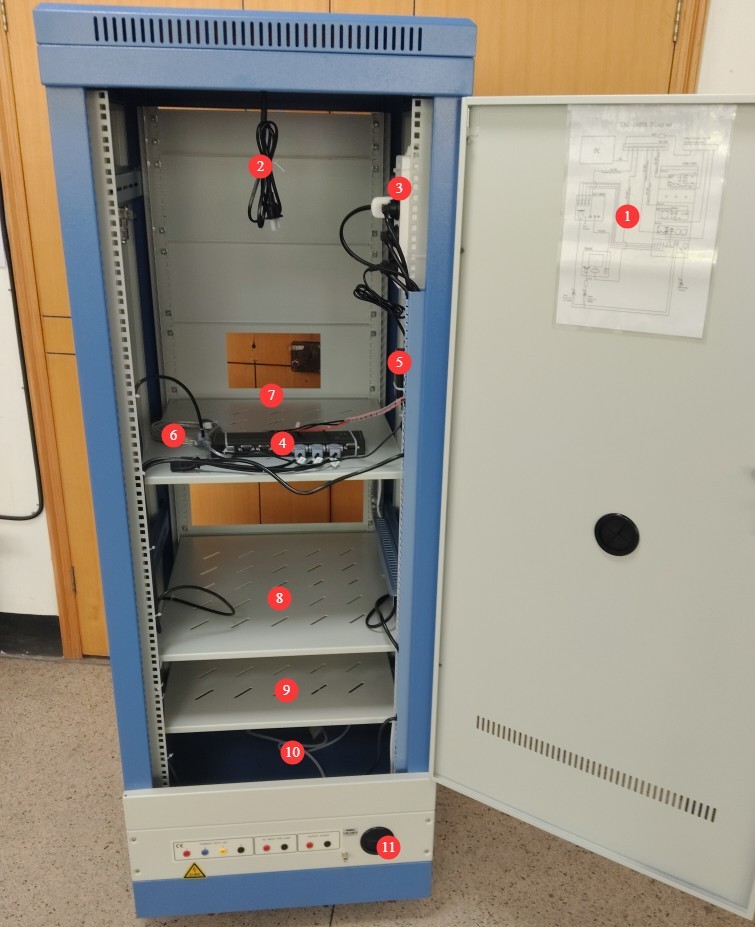
Gambar 1
3.1.2 Pemasangan Meter Daya LS
| Jumlah | Note |
| ① | Terhubung melalui kabel komunikasi RS-485; ujung lainnya sudah terhubung ke kotak komunikasi RS-485 di dalam kabinet. |
| ② | Kabel daya sudah terhubung; ujung lainnya sudah terhubung ke stopkontak di dalam kabinet. |
| ③ | Kabel uji V1, dihubungkan ke terminal merah tegangan V pada meteran daya. |
| ④ | Kabel uji V2, dihubungkan ke terminal hitam tegangan V pada meteran daya. |
| ⑤ | A1 test lead, connected to the red terminal of the power meter’s current A |
| ⑥ | Kabel uji A2, dihubungkan ke terminal hitam dari meteran daya arus A. |
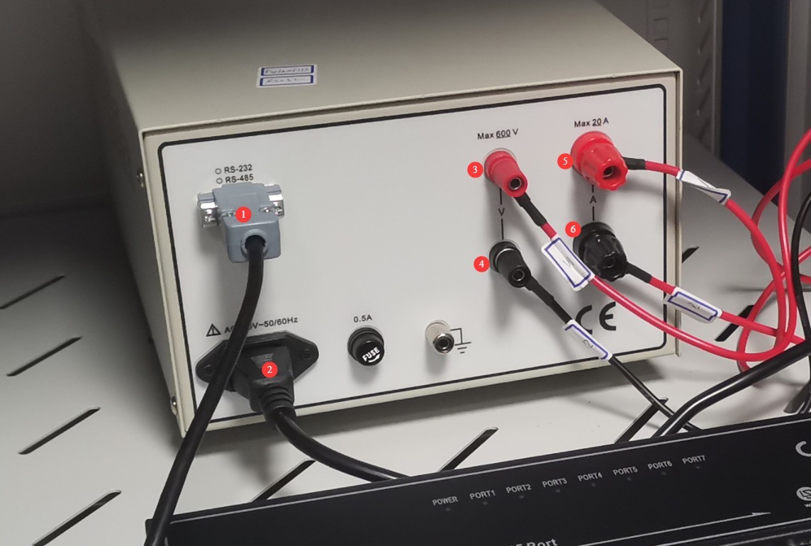
Gambar 3
3.1.3 Instalasi Catu Daya DC
| Jumlah | Note |
| ① | Terhubung melalui kabel komunikasi RS-485; ujung lainnya sudah terhubung ke kotak komunikasi RS-485 di dalam kabinet. |
| ② | Hubungkan kabel keluaran daya DC, pastikan untuk mencocokkan terminal positif dan negatif. |
| ③ | Kabel daya sudah terhubung; ujung lainnya sudah terhubung ke stopkontak di dalam kabinet. |
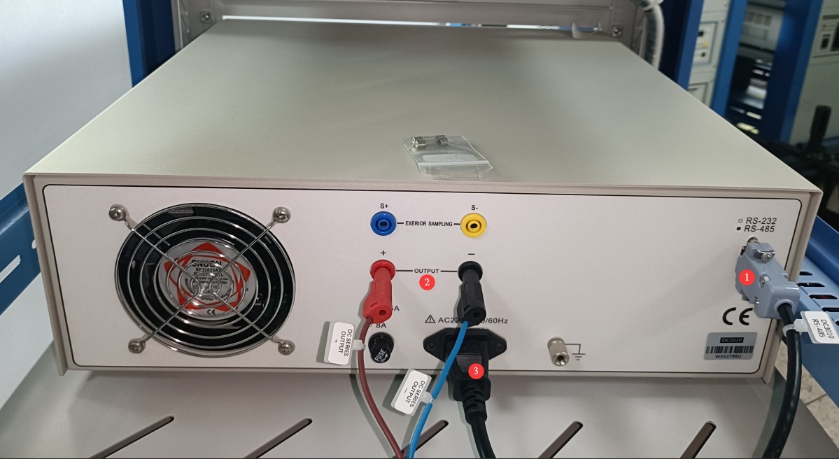
Gambar 4
3.1.4 Instalasi Daya AC
Silakan cari kabel keluaran daya AC berikut di antara aksesori:
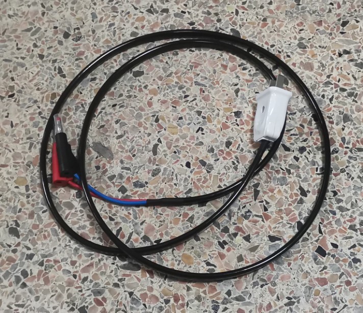
Gambar 5
| Jumlah | Note |
| ① | Terhubung melalui kabel komunikasi RS-485; ujung lainnya sudah terhubung ke kotak komunikasi RS-485 di dalam kabinet. |
| ② | Kabel daya sudah terhubung; ujung lainnya sudah terhubung ke stopkontak di dalam kabinet. |
| ③ | Lewatkan kabel keluaran daya AC melalui lubang kabel ④ dan sambungkan ke posisi ⑤. |
| ④ | Lubang kawat |
| ⑤ | Kabel keluaran daya AC: Lewatkan melalui lubang kabel ④ dan sambungkan ke posisi ③. |
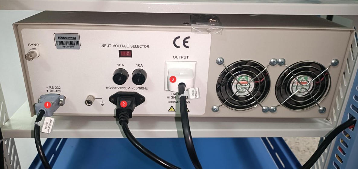
Gambar 6
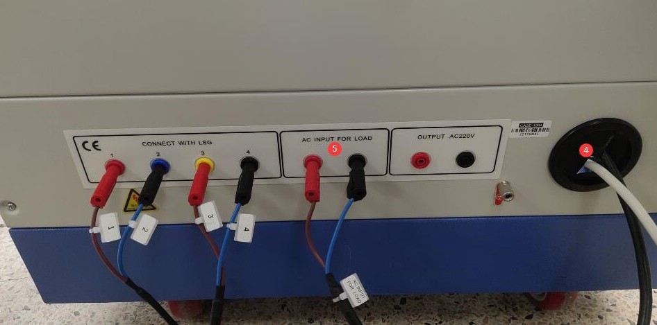
Gambar 7
3.2 Placement of the Host and Installation of the Photometric Probe
3.2.1 Server Placement
The four feet on the bottom of the unit are height-adjustable.
| Jumlah | Note |
| ① | Turn the screw at the bottom to raise the leg until it is off the ground. |
| ② | At the same time, make sure the top screw isn’t pressing against anything; you can unscrew it slightly. |
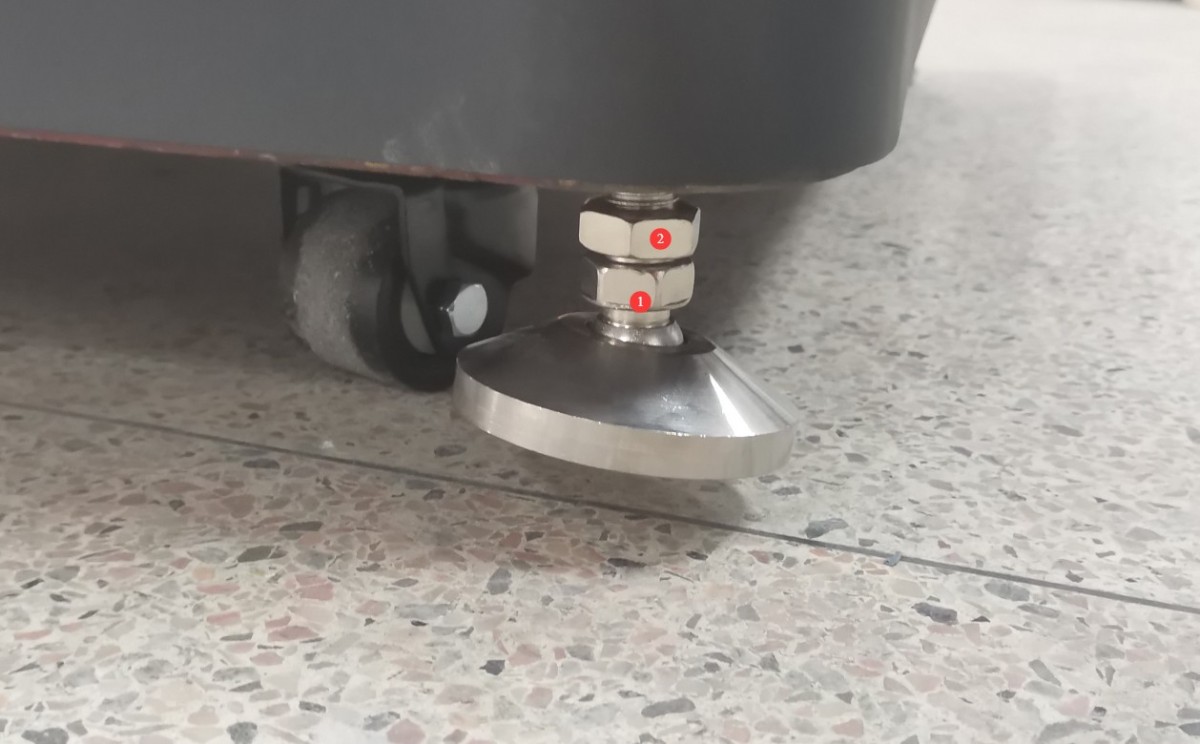
Gambar 14
Position the goniophotomoeter in the correct location according to the darkroom blueprints. Align the four sides of the base as closely as possible with the walls of the darkroom. Then, remove the auxiliary arm.
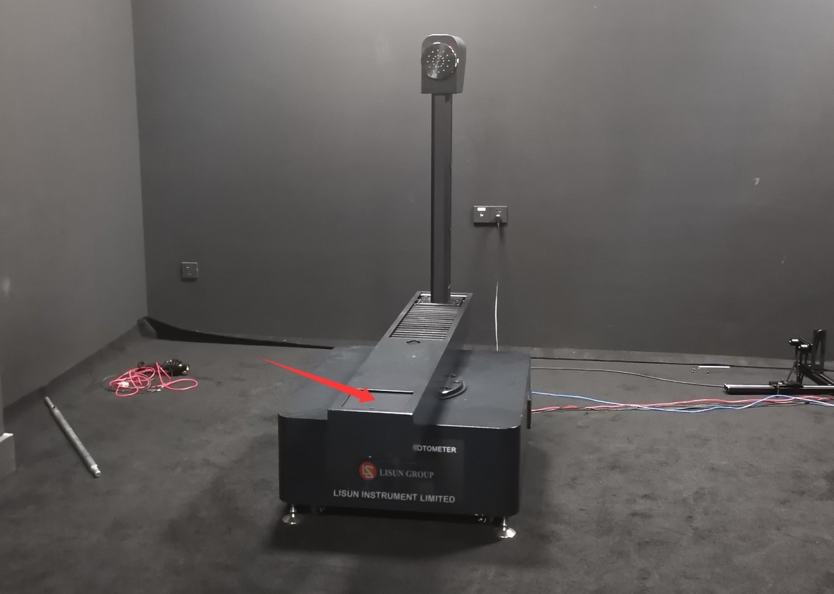
Gambar 15
Next, please turn all four legs of the Goniophotomoeter until they are in contact with the floor.
3.2.2 Perakitan Probe Fotometri dan Dudukan Probe
Take, for example, a darkroom with only one photometer.
Rakitlah probe fotometri dan dudukan probe, lalu posisikan keduanya di lokasi yang sesuai menurut gambar ruang gelap; untuk saat ini tidak perlu mengencangkannya dengan sekrup.
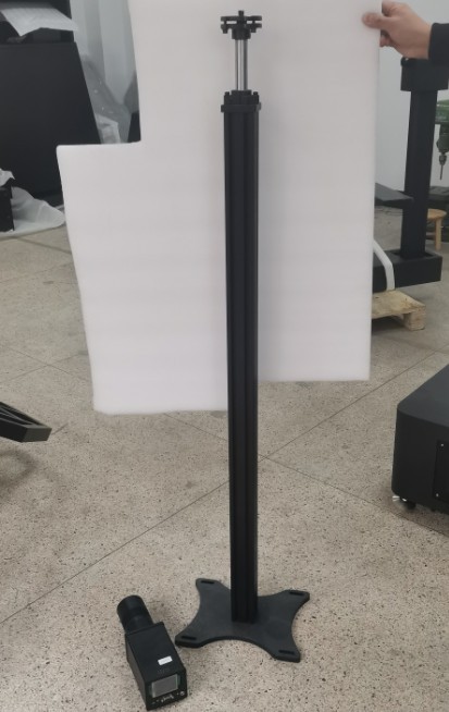
Gambar 16
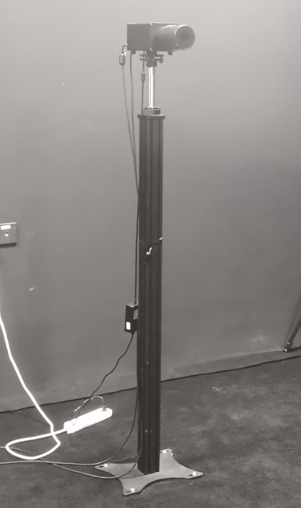
Gambar 17
3.2.3 Pengkabelan Sistem
| Jumlah | Note |
| ① | Keempat blok terminal ① pada kabinet terhubung ke Goniophotometer ⑩; cukup pasangkan satu per satu sesuai dengan nomornya. |
| ② | The two terminals are connected to the terminal block inside the cabinet and are used to supply power to all equipment in the darkroom, including the Goniophotomoeter , luminance probe, and spectroradiometer. This makes it convenient to control all equipment in the darkroom using the power switch on the cabinet. Note: The equipment in the darkroom can also be powered directly from the mains. |
| ③ | Cabinet grounding terminal: Please connect it to ground using a wire. |
| ④ | Kabel daya kabinet, terhubung ke sumber daya 220V, 50/60 Hz. |
| ⑤ | Kabel Daya untuk Unit Utama Goniophotometer |
| ⑥ | Hubungkan terminal ground Goniophotometer ke ground menggunakan kawat. |
| ⑦ | Kabel komunikasi RS-485, dengan ujung lainnya terhubung ke kotak komunikasi RS-485 di dalam kabinet. |
| ⑧ | Photometer probe trigger wire; connect to probe ⑬. When only one probe is installed, the default setting is near-field (N). |
| ⑨ | If you have only one photometer in your darkroom, then the far-field (F) sensor does not need to be connected. |
| ⑩ | Keempat blok terminal ⑩ pada Goniophotometer terhubung ke kabinet ①; cukup pasangkan satu per satu sesuai dengan nomornya. |
| ⑪ | Adaptor Daya untuk Probe Fotometri |
| 1 | Kabel komunikasi RS-485 untuk probe fotometri; ujung lainnya terhubung ke kotak komunikasi RS-485 di dalam kabinet. |
| ⑬ | Kabel pemicu probe fotometri, terhubung ke unit utama ⑧ dari Goniophotometer |
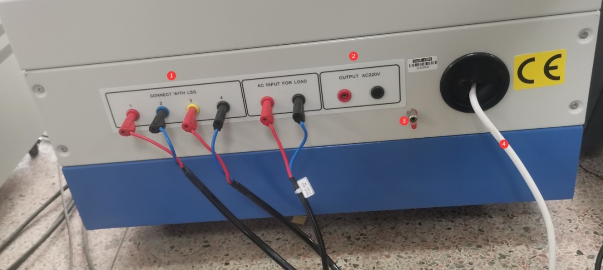
Gambar 18
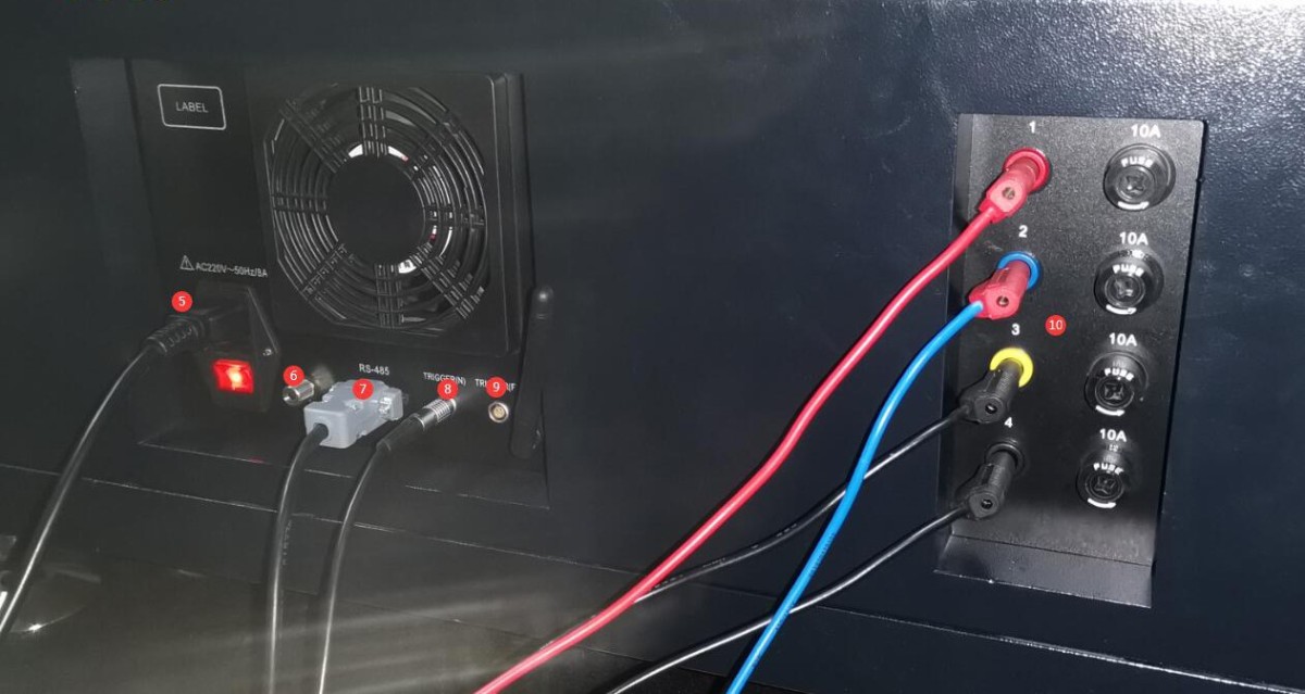
Gambar 19
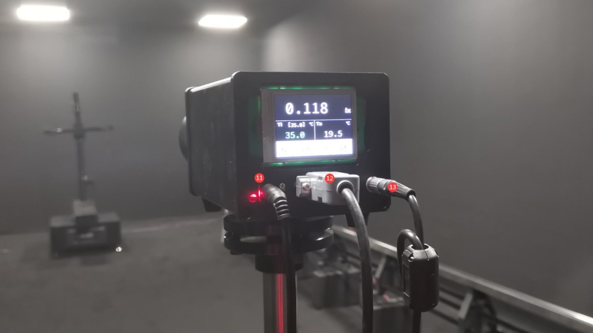
Gambar 20
3.3 Installation of The Spectroradiometer
3.3.1 Assembly of The Spectroradiometer and Mounting Bracket
Assemble the Spectroradiometer and the mounting bracket as shown in the figure below.
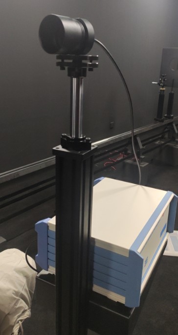
Gambar 22
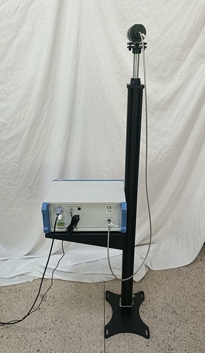
Gambar 23
Place it in the appropriate position according to the darkroom drawings. In the drawing below, the item circled is the LSG-9000CG Spectroradiometer.
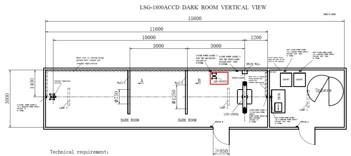
Gambar 23.1
Principles for positioning the spectroradiometer: Place it as close to the wall as possible without obstructing the light path of the photometer probe; place it as close to the main unit of the goniophotomoeter as possible to obtain more accurate colorimetric parameters; ensure that the goniophotomoeter does not come into contact with the spectroradiometer or its mount when rotating.
Then simply secure the base to the floor with screws.
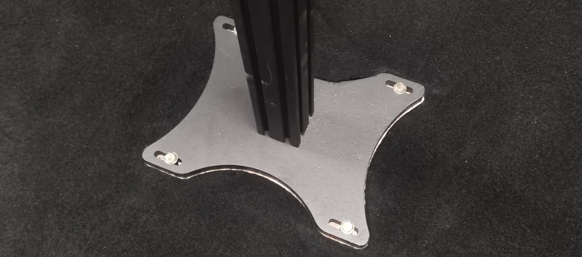
Gambar 48
3.3.2 Spectroradiometer Wiring
| Jumlah | Note |
| ① | Kabel komunikasi RS-485, dengan ujung lainnya terhubung ke kotak komunikasi RS-485 di dalam kabinet. |
| ② | Adaptor daya |
| ③ | Serat optik |
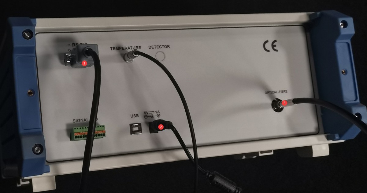
Gambar 24
3.3.3 Optical Fiber Mounting
The other end of the Optical Fiber has a black ferrule; make sure the ferrule is securely tightened.
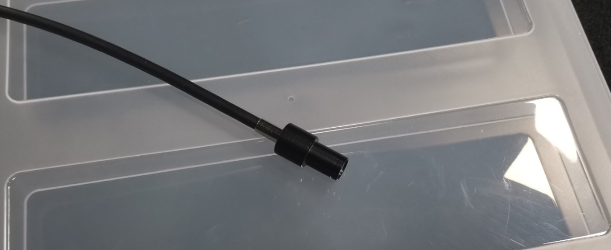
Gambar 25
Secure the sleeve end to the Optical Fiber bracket and fasten it with screws.
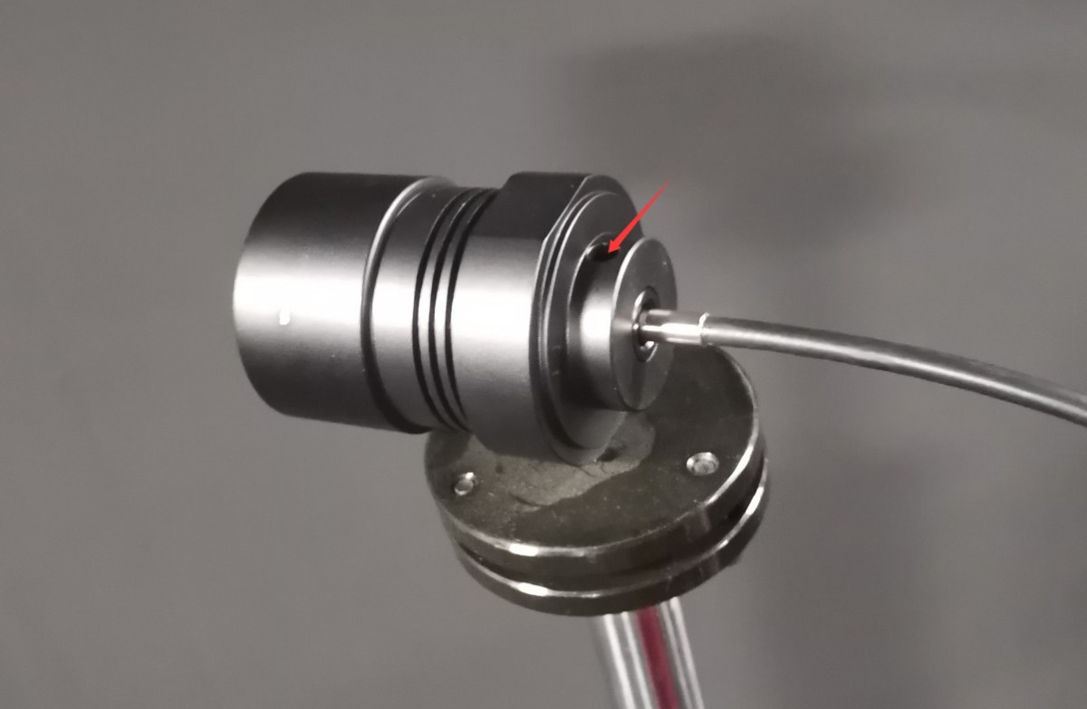
Gambar 26
4. Instalasi dan Pengaturan Perangkat Lunak
4.1 Instalasi Perangkat Lunak dan Driver
4.1.1 Lingkungan Eksekusi Perangkat Lunak
Persyaratan Sistem: Windows 7/8/10/11 (32-bit/64-bit); komputer harus memiliki setidaknya satu port USB.
Instalasi 4.1.2
| Jumlah | Note |
| ① | Perangkat Lunak Goniophotometer Seri LSG—silakan klik dua kali untuk menginstal |
| ② | The APK file can be copied to an Android phone for installation. The app is intended solely for rotating the Goniophotomoeter and cannot be used for testing. The software includes all the app’s features; this manual uses the software as an example . Note: The APK file is compatible only with the LSG-1890B ke LSG-6000 models; it is not compatible with the LSG-1800A. |
| ③ | RS485 Communication Module Driver—Double-click to install |
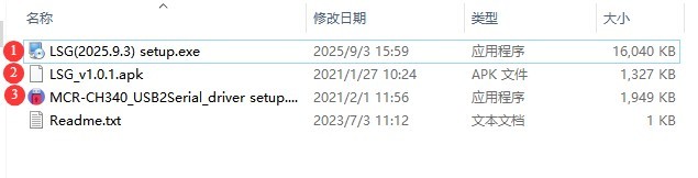
Gambar 27
4.1.3 Penanganan Pengecualian
Jika perangkat lunak antivirus atau Windows Firewall Anda menandai sebuah file sebagai mencurigakan selama proses instalasi perangkat lunak, harap nonaktifkan sementara perangkat lunak antivirus atau Windows Firewall tersebut, lalu coba instal perangkat lunak itu lagi.
If the software fails to open when you double-click the icon after a successful installation, please verify that you are logged in to your computer with an administrator account. If the software still does not open after logging in with an administrator account, right-click the software icon to open its Properties window. On the Compatibility tab, check the box next to “Run this program as an administrator,” click “Apply,” and then double-click the icon again to open the software.
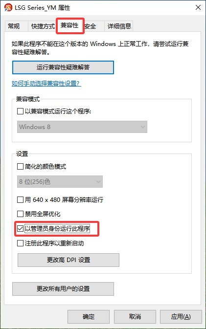
Gambar 28
4.2 Pengaturan Perangkat Lunak
First, turn on the cabinet’s power switch, then power on all system devices, including all equipment inside the cabinet, the Goniophotomoeter main unit, the photometric probe, and the Spectroradiometer. Double-click to run the software. The first time you run the software, it will automatically open the system configuration interface. Select the correct model for all the devices you have purchased.
| Jumlah | Note |
| ① | To select a goniophotomoeter model, click the drop-down list on the right. The model you purchased is the LSG-1800A. |
| ② | Near-field photometer probe; select photometer model PM400C |
| ③ | Far-field photometric probe—if you have not purchased one, please select “Not Installed.” |
| ④ | Spektroradiometer medan dekat; pilih model spektroradiometer LMS-9000CG |
| ⑤ | Model catu daya AC biasanya berasal dari Seri LSP. |
| ⑥ | Model catu daya DC umumnya disebut sebagai Seri DC. |
| ⑦ | Model meteran daya: Nomor model tercetak di panel depan meteran daya. Silakan periksa dan pilih model yang sesuai. |
| ⑧ | Once you have selected all the correct models, click “Auto-detect Port.” |
| ⑨ | Setelah pencarian semua port selesai, klik “OK” untuk menyimpan dan keluar. |
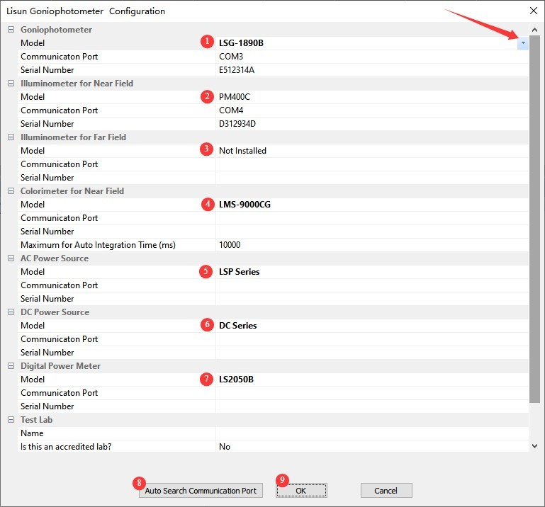
Gambar 29
Note: If a communication error occurs during the automatic port search, please read the error message carefully, check whether the corresponding device is powered on, and verify that the RS-485 communication cable is properly connected. Once you have confirmed these points, click “Automatic Port Search” again until communication is established with all devices.
After clicking OK, the software automatically proceeds to the screen for saving the database file. From then on, all test reports will be automatically saved in this database file.
| Jumlah | Note |
| ① | Please select the path where you want to save the database file. Please do not save it to the desktop or inside the Desktop folder. |
| ② | Masukkan nama file |
| ③ | Cukup klik “Simpan” |
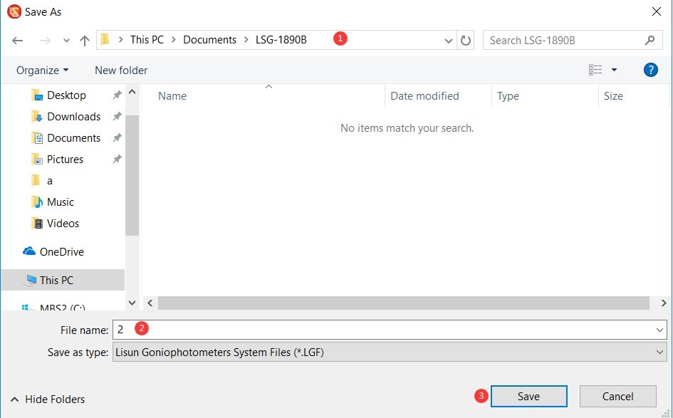
Gambar 30
5. Kalibrasi peralatan kamar gelap (Setiap langkah harus dilakukan dengan hati-hati dan teliti; jika tidak, dapat mengakibatkan data kalibrasi yang salah dan hasil pengujian yang tidak normal.)
5.1 Horizontal Commissioning of the Host Machine
5.1.1 Single-Line Laser Ready
Insert the batteries into the laser pointer and turn it on.
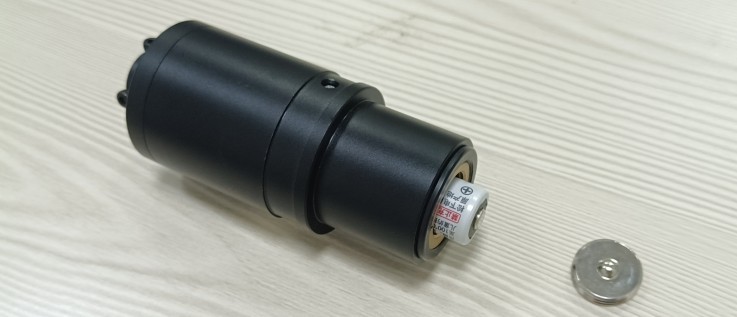
Gambar 31
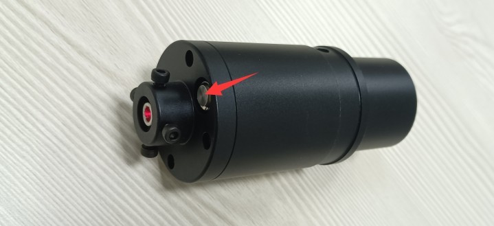
Gambar 31.1
Install the single-line laser onto the Goniophotomoeter and secure it.
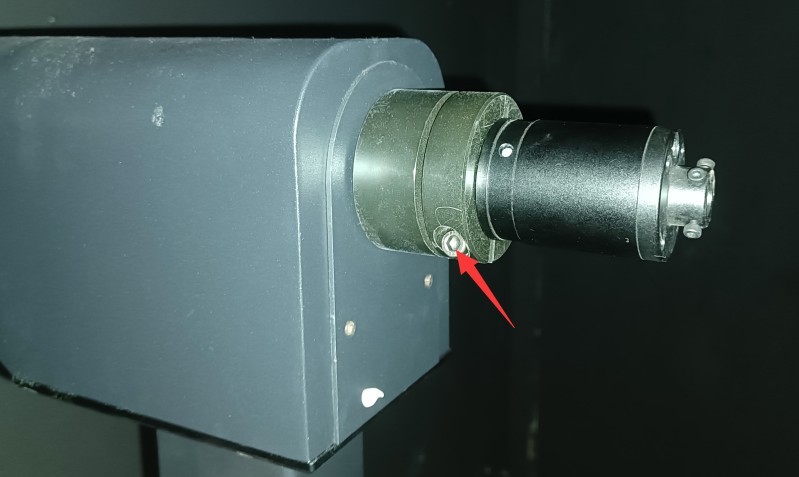
Gambar 31.2
Buka perangkat lunak.
| Jumlah | Note |
| ① | Click to switch angle modes |
| ② | Klik ① untuk menampilkan sudut C-Gamma di sini, bukan sudut B-Beta. |
| ③ | Kemudian klik untuk membuka antarmuka kontrol sudut. |
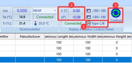
Gambar 31.3
| Jumlah | Note |
| ① | Select “Near-Field Photometric Probe” |
| ② | Masukkan 0 |
| ③ | Click to rotate the Gamma axis to the 0-degree position |
| ④ | Click, and the single-character laser begins to rotate on its own. |
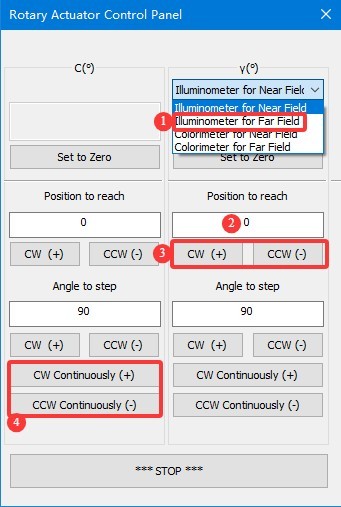
Gambar 31.4
Secure a sheet of white paper at the far end of the darkroom. When you trace the red laser dot with a pen, it will create a circular path of varying sizes, as shown by the black circular path in the figure below.
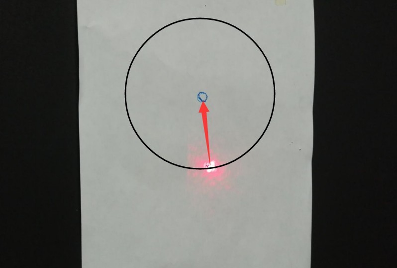
Gambar 31.5
Click the “Stop” button on the “Angle Control” interface to stop the straight-line laser from rotating. Then, based on the actual situation, adjust the four small Allen screws shown in the figure below to align the straight-line laser spot with the exact center of the circular path, as indicated by the red arrow in the figure above.
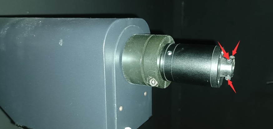
Gambar 31.6
Then restart the straight-line laser’s rotation, redraw the trajectory, and repeat the above steps until the trajectory of the straight-line laser dot forms a single point (or until the trajectory radius is small enough), rather than a circle. Then click the “Stop” button on the “Angle Control” interface to stop the straight-line laser from rotating. Once debugging is complete, all four small Allen screws on the single-line laser should be fully tightened.
Note: Once the single-line laser has been properly calibrated, it must remain attached to the Goniophotomoeter until the installation and calibration process is complete before being removed.
5.1.2 Crosshair Laser Ready
Find the cross-hair laser device and tripod.
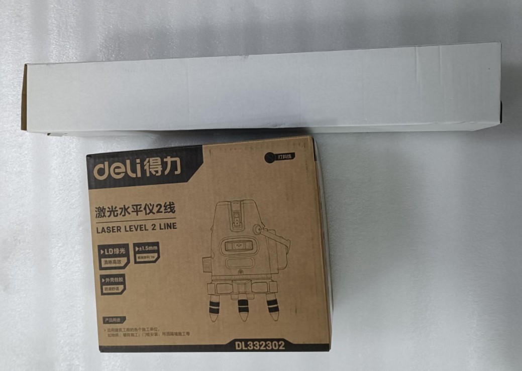
Gambar 32
Lepaskan laser garis silang dan baterai. Masukkan baterai ke dalam laser garis silang. Sakelar daya terletak di sisi perangkat. Putar sakelar ke posisi "buka kunci" untuk menghidupkan perangkat.
| Jumlah | Note |
| ① | Power switch: Turn it to the “Unlock” position to turn on the power. |
| ② | VH refers to vertical and horizontal laser switches, respectively. |
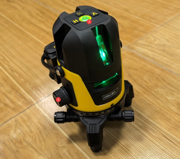
Gambar 33
Mount the cross-hair laser on the tripod.
Catatan: Laser garis silang ini memiliki fitur perataan otomatis. Jika tidak rata, alarm akan berbunyi. Hal ini mungkin disebabkan oleh permukaan yang tidak rata atau tripod yang tidak terpasang dengan benar. Pastikan laser garis silang tetap rata setiap saat selama penggunaan.
5.1.2 Steps for Horizontal Commissioning of the Host Machine
According to the darkroom drawings, the center height of the LSG-1800A goniophotomoeter is 1375 mm. Using a tripod, adjust the height of the horizontal laser beam from the crosshair to 1375 mm. At this height, the horizontal laser beam should pass through the center of all light-transmitting holes in the darkroom partition.
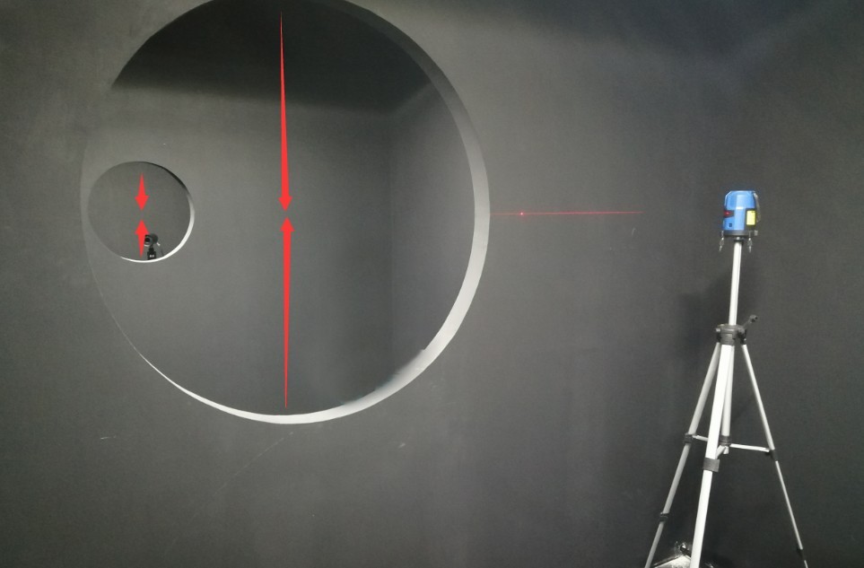
Gambar 34
Please note: Do not place any objects on the Goniophotomoeter or within its rotation range to prevent damage to the equipment during rotation.
| Jumlah | Note |
| ① | Still opting for a near-field photometric probe |
| ② | Click the continuous rotation button in any direction. The gamma axis of the Goniophotomoeter will then begin to rotate continuously. |
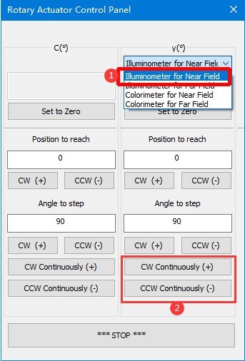
Gambar 36
At this point, observe the horizontal laser beams emitted by the single-line and cross-line lasers from the main axis of the Goniophotomoeter.
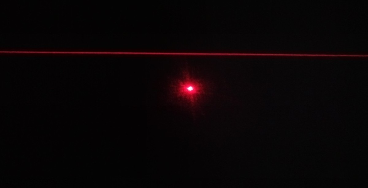
Gambar 37
Then, using an appropriate wrench, raise the goniophotomoeter and level it by adjusting the height of its four legs. The final result of the calibration: Regardless of the Gamma angle of the goniophotomoeter, its straight laser beam perfectly aligns with the horizontal laser beam, as shown in the figure below.
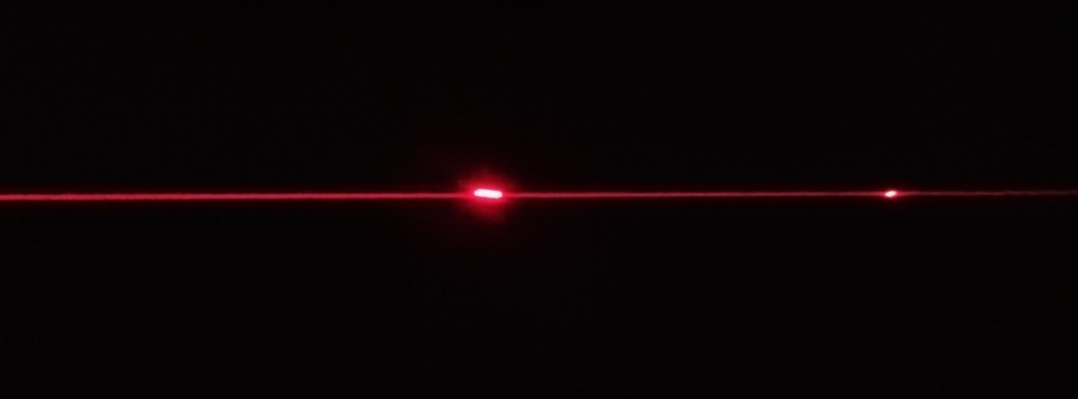
Gambar 38
You’ll need plenty of patience to complete this step. Once the adjustment is complete, ensure that all four feet of the main unit are firmly on the ground. You can then click the “Stop” button on the software’s angle control interface to stop the Goniophotomoeter from rotating. Next, secure the four legs of the Goniophotomoeter by tightening the screws at their tops. Once the main unit is properly positioned and leveled, do not move it again, as doing so will cause deviations in the test results.
5.2 Kalibrasi Probe Fotometri
5.2.1 Calibration of the Photometric Probe at the 0-Degree Position
| Jumlah | Note |
| ① | Tetap memilih fotometer medan dekat |
| ② | Masukkan 0 |
| ③ | Click any rotation direction to rotate the Gamma axis back to the 0-degree position. |
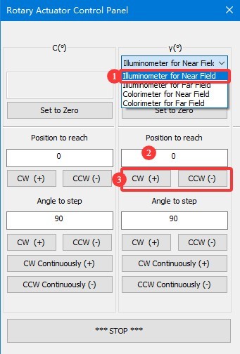
Gambar 39
Verify that the single-line laser beam is passing through the exact horizontal center of the last partition at this point.
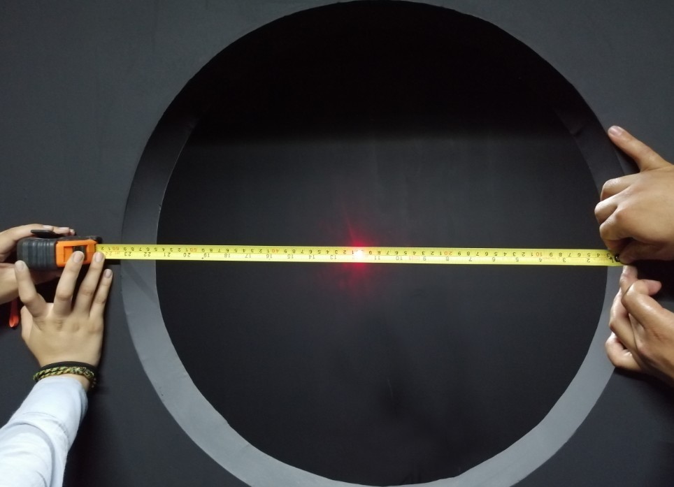
Gambar 40
If not, follow the steps below.
| Jumlah | Note |
| ① | Please enter a small angle value here based on the actual situation, such as 1, 0.1, 0.05, etc. |
| ② | Select a rotation direction and rotate the Gamma axis until the laser beam passes through the exact center of the horizontal plane of the last partition. |
| ③ | Click “Set to 0 Degrees” to set the current position of the Gamma axis on the near-field photometric probe to 0 degrees. The password is LISUNGROUP. |
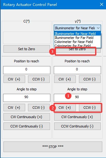
Gambar 40.1
Note 1: After setting the Gamma axis of the near-field photometer to 0 degrees, do not arbitrarily set it to 0 degrees again, as this will cause the test results to be inaccurate.
Note 2: Definition of angles for the Goniophotomoeter. The direction directly facing the photometer probe is defined as 0 degrees/360 degrees. When rotating clockwise, the angle increases from 0 degrees to 360 degrees; when rotating counterclockwise, the angle decreases from 360 degrees to 0 degrees. Since angle notation may vary, -90 degrees and 270 degrees correspond to the same position.
5.2.2 Mounting the Photometric Probe
Rotate the light probe’s light shield counterclockwise and remove it.
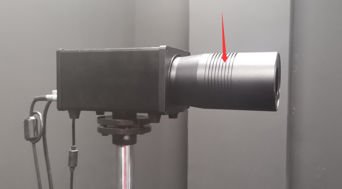
Gambar 41
Kotak kemasan lampu standar berisi cermin kecil.
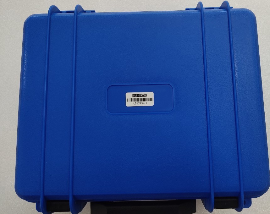
Gambar 42
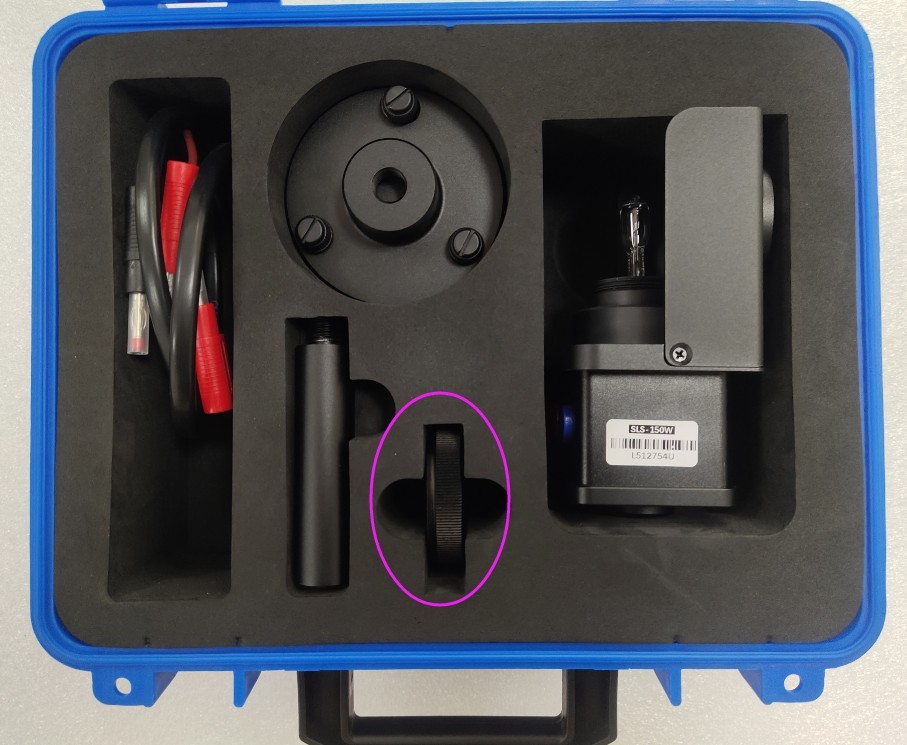
Gambar 43
Lepaskan reflektor kecil dan pasang ke probe.
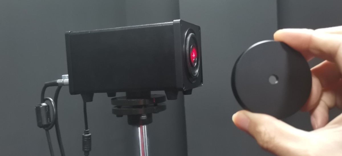
Gambar 44
At this point, the Gamma axis of the near-field photometric probe is still at the 0-degree position. Slightly move the probe base and adjust the screws at points ① and ② to adjust the probe’s height and orientation. Position the probe so that the straight laser beam coming from the main axis hits the exact center of the reflector, and ensure that the reflected beam returns along the same path.
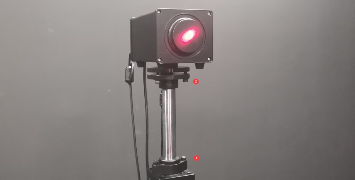
Gambar 45
Kemudian, kencangkan alas braket probe ke lantai dengan sekrup.
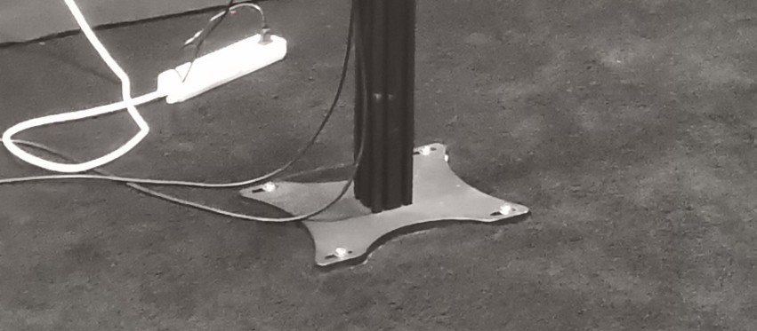
Gambar 46
Once secured, you may need to make slight adjustments to the probe’s height and orientation so that the straight laser beam continues to hit the exact center of the reflector and the reflected beam travels back along the same path. After calibration is complete, ensure that all screws are tightened. Then remove the reflector and reinstall the light probe’s light shield.
Note: Once the probe’s position and orientation have been set, do not adjust them, as doing so may cause discrepancies in the test data.
Anda dapat mengamankan adaptor daya probe fotometer ke braket probe seperti yang ditunjukkan pada gambar di bawah untuk melindungi jack daya probe.
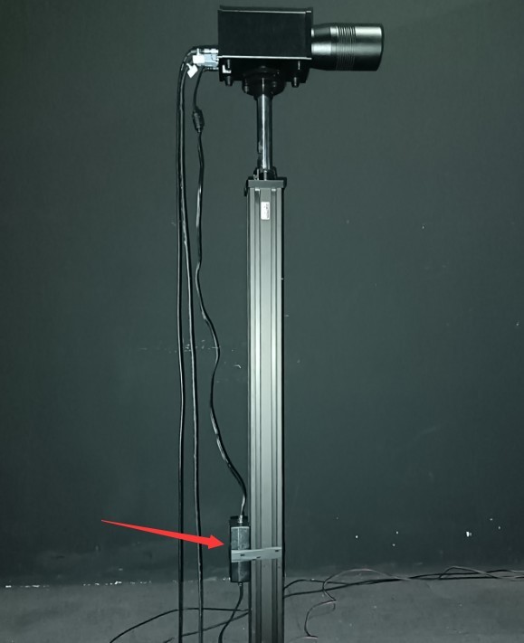
Gambar 47
5.3 Calibration of the Spectroradiometer
Attach the small reflector to the Optical Fiber bracket.
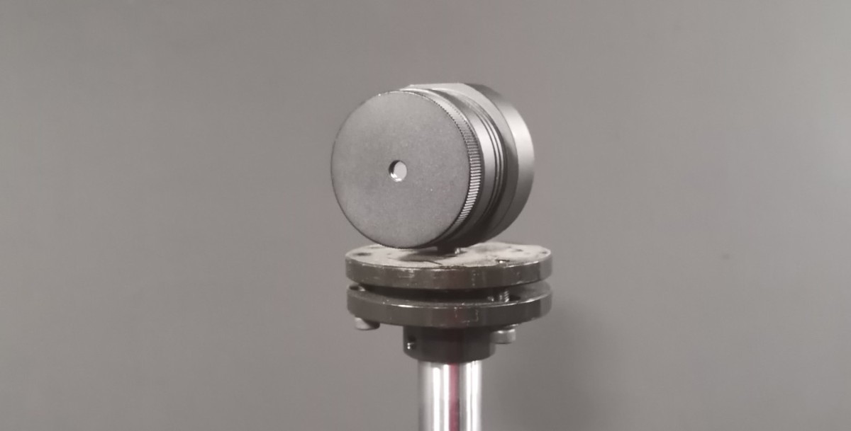
Gambar 49
Software-based control interface.
| Jumlah | Note |
| ① | Selecting a Near-Field Spectroradiometer |
| ② | Rotate the Gamma angle of the near-field Spectroradiometer until the single-line laser on the main axis is directed toward the Optical Fiber holder. |
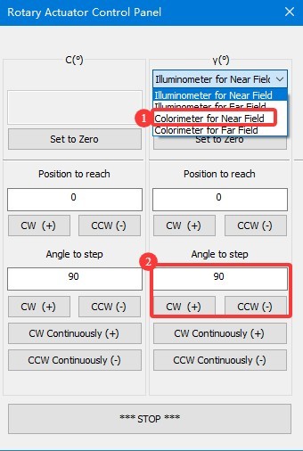
Gambar 50
Slightly adjust the angle of the Gamma axis and use the screws on② the spectrometer’s Optical Fiber mount① to change the height and orientation of the small mirror so that the line laser hits the exact center of the mirror and the reflected beam travels back along the same path.
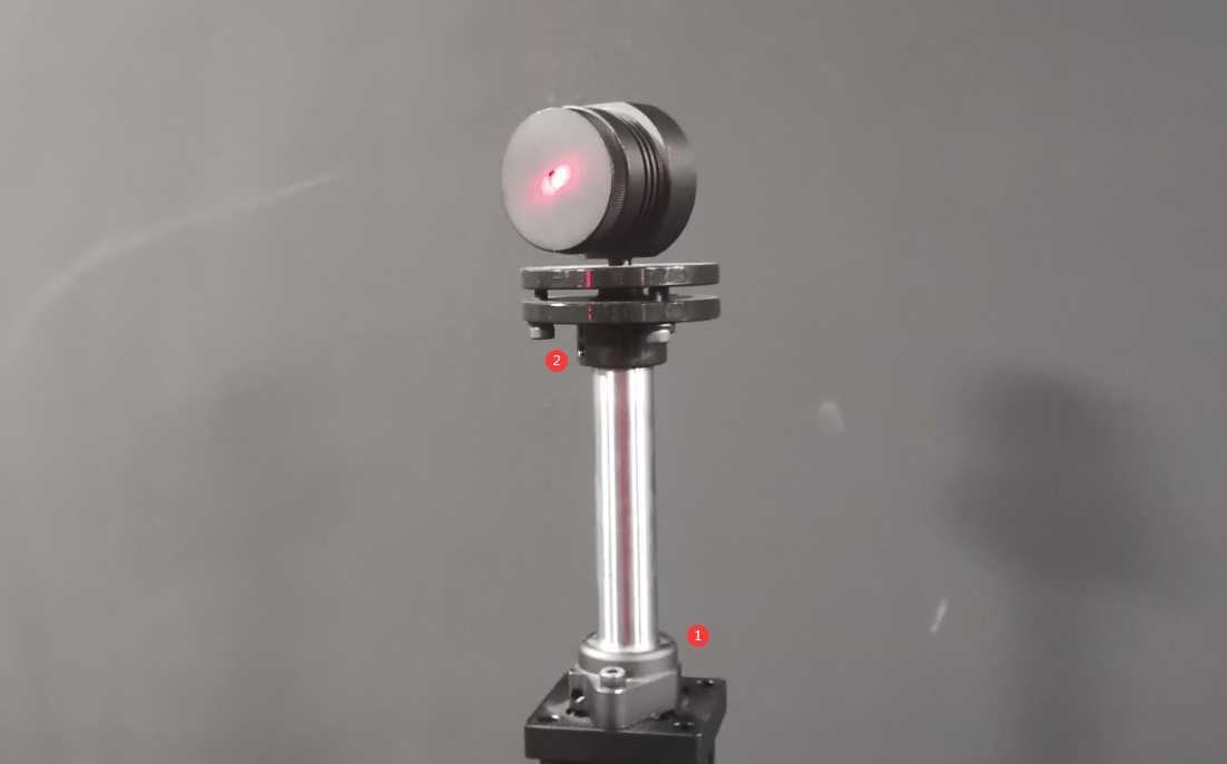
Gambar 51
Once the adjustment is complete, all screws should be fully tightened. Then, click “Set 0 Degrees” on the software’s angle control interface to set the current position of the near-field Spectroradiometer’s Gamma axis to 0 degrees. The password is LISUNGROUP.
Remove the small reflector and store it safely. Reinstall the Optical Fiber bracket sleeve.
Note: After setting the Gamma axis of the near-field Spectroradiometer to 0 degrees, do not set it to 0 degrees again arbitrarily, as this will cause the test results to be inaccurate.
5.4 Cross-Line Laser Installation
Finally, the crosshair laser must be mounted on the side wall of the darkroom. Depending on the specific layout of each darkroom, the crosshair laser can be mounted on either the left or right side wall. Take the darkroom layout shown in the figure below as an example.
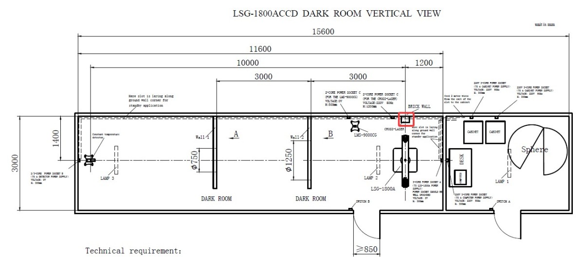
Gambar 52
Go to the angle control screen.
| Jumlah | Note |
| ① | Memilih Probe Fotometri Medan Dekat |
| ② | Enter 90 (if the installation position of the crosshair laser on your darkroom blueprint is different, enter -90) |
| ③ | Click to rotate the Gamma axis to a 90-degree position, so that the main-axis laser beam is directly aligned with the position where the crosshair laser is installed. |
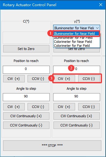
Gambar 53
Secure the crosshair laser to the triangular mount we provide.
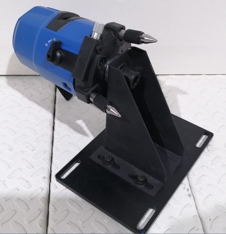
Gambar 54
Turn on the crosshair laser and use the direction of the single-line laser to roughly determine the position of the crosshair laser.
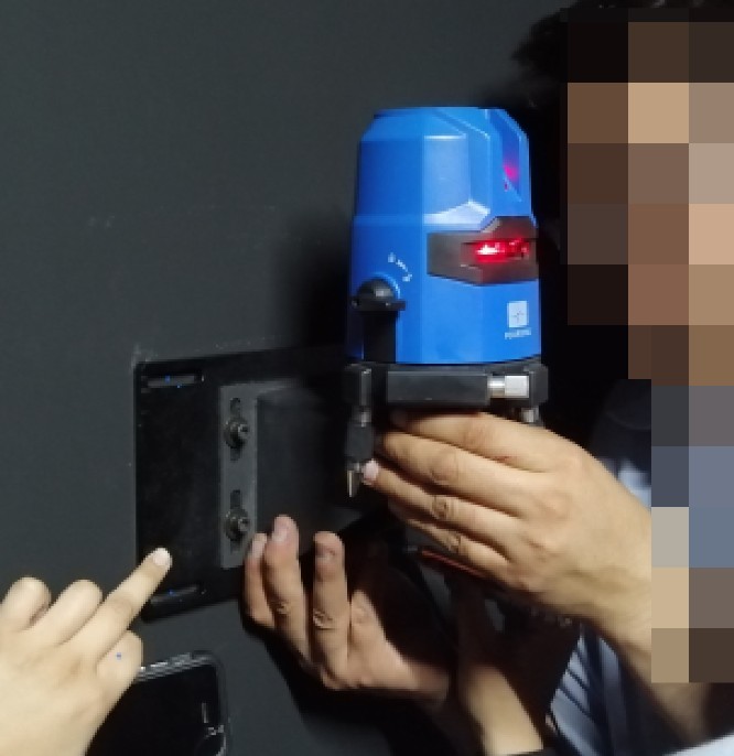
Gambar 55
Fine-Tune the Position of the Crosshair Laser: The centerline of the horizontal laser should be perfectly aligned with the centerline of the crosshair laser. You can verify and adjust the position using the following method. Place a sheet of white paper at the exit of the crosshair laser and at the exit of the single-line laser. If the centerline of the single-line laser aligns with the centerline of the crosshair laser at both locations, you can confirm that the position and orientation of the crosshair laser are correct.
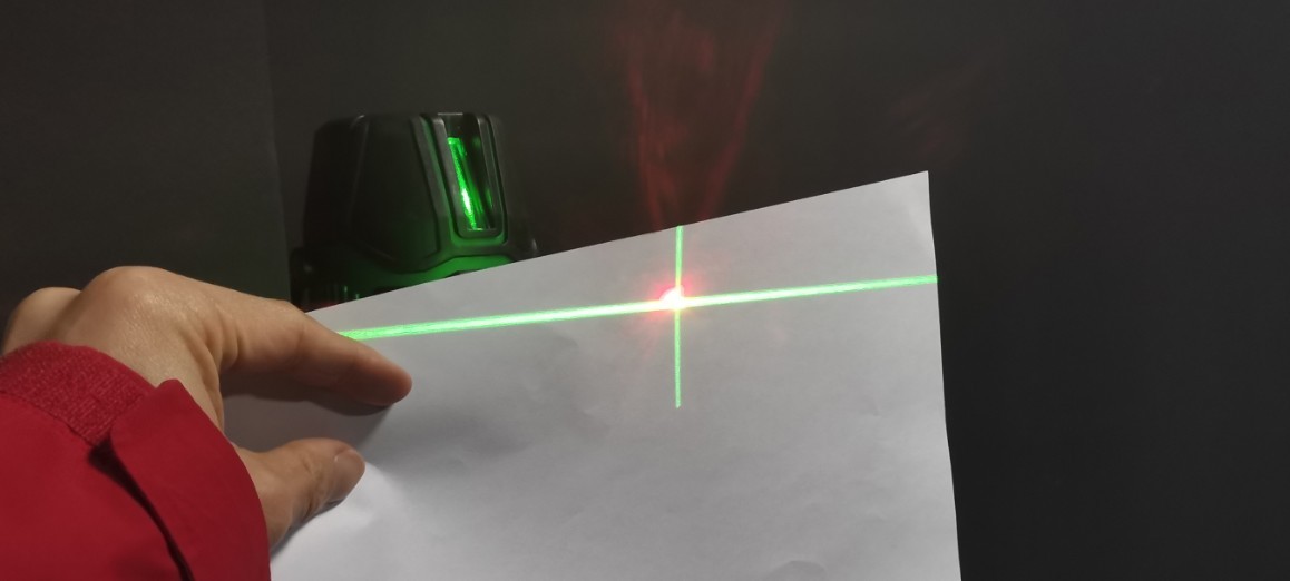
Gambar 56
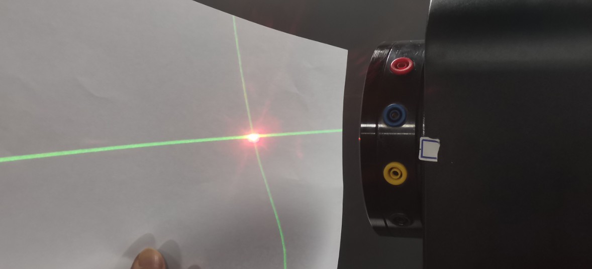
Gambar 57
Next, secure the cross-laser tripod to the wall using the screws. Once secured, you can still loosen the screws if necessary to make slight adjustments to the cross-laser’s position horizontally and vertically, ensuring it remains correctly aligned. After calibration is complete, all screws should be tightened securely.
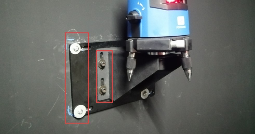
Gambar 58
Then rotate the gamma axis back to the 0-degree position. The cross-shaped laser beam is projected onto the opposite wall. This creates a permanent mark. In other words, when the cross-shaped laser beam is projected in this direction, it indicates the horizontal and vertical center positions of the Goniophotomoeter. This mark is needed for both calibration and testing.
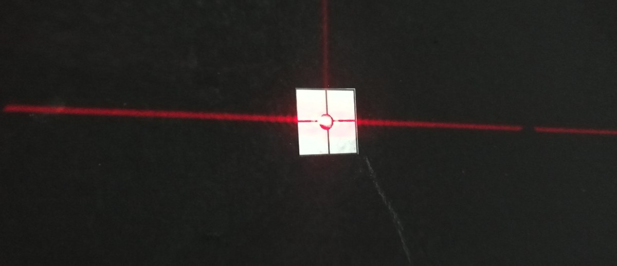
Gambar 59
Installation and commissioning are complete. Remove the flat-head laser from the main shaft of the Goniophotomoeter and store it safely.
5.5 Membersihkan
You may shut down all equipment. When shutting down the equipment, first turn off the power switch on each device, and then turn off the main power switch for the cabinet. Next, thoroughly clean the darkroom and control room. To prevent dust from entering the equipment, cover the equipment with dust-proof cloths before cleaning. After cleaning, turn all equipment back on and continue with the calibration and testing procedures.
Catatan: Jaga agar ruang gelap sebisa mungkin bebas debu selama penggunaan.
6. Kalibrasi
6.1 Pemasangan dan Pengoperasian Lampu Standar
6.1.1 Installation of the Standard Lamp
First, turn on the crosshair laser on the wall, and rotate it to ensure that it points to the mark on the opposite wall.
Buka kotak lampu standar.
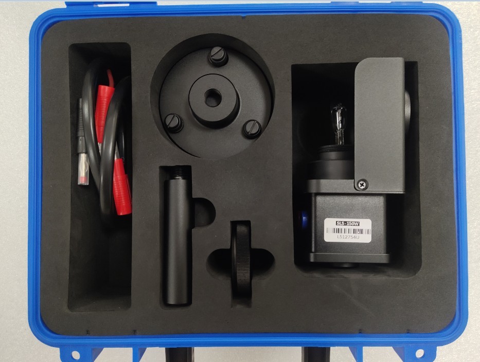
Gambar 60
Then assemble the standard lamp bracket as shown in the figure below.
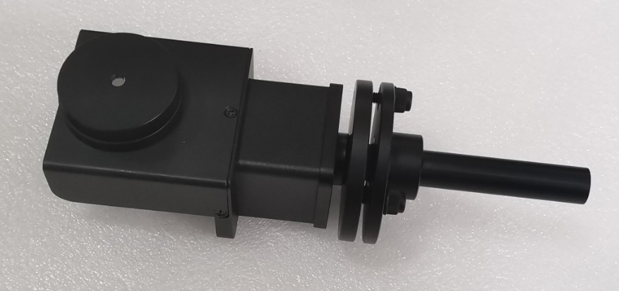
Gambar 61
The main shaft of the Goniophotomoeter should still be aligned directly with the photometric probe, i.e., the probe’s 0-degree position. Locate the alignment rod and install it at the center of the Goniophotomoeter. Then remove the top section.
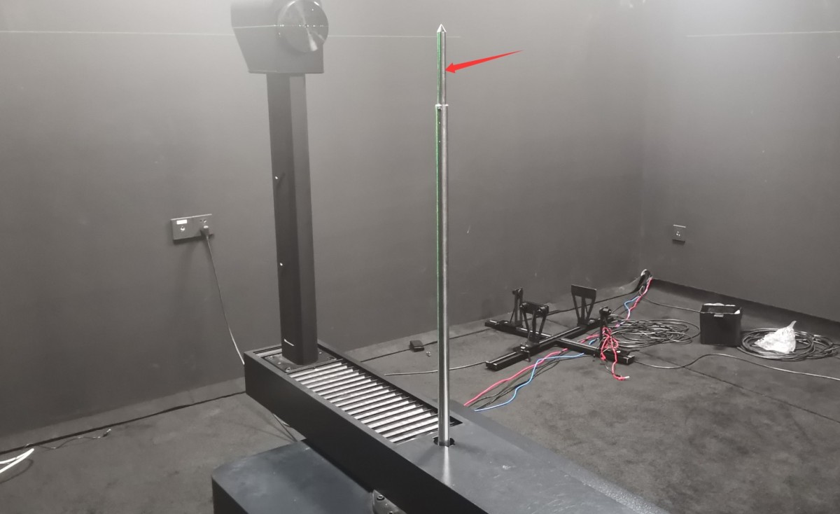
Gambar 62
Please follow the instructions below to connect the wires.
| Jumlah | Note |
| ① | The main shaft of the goniophotomoeter has four terminals for connecting the power cables and sampling cables of the standard lamp and sample luminaire. Use a jumper wire to short-circuit the red and yellow terminals together, and the black and blue terminals together. |
| ② | Connect the power cord of the standard lamp/sample lamp to the red and blue terminals on the main shaft. |
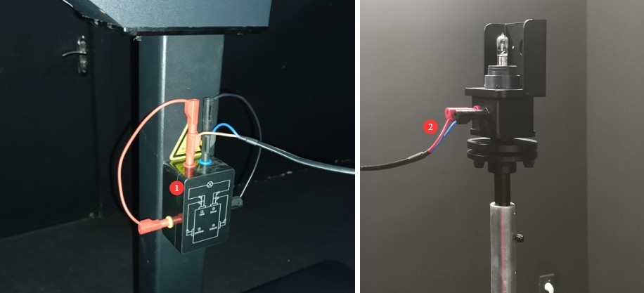
Gambar 63
6.1.2 Calibration of the Standard Light Direction
| Jumlah | Note |
| ① | Loosen the screw here to adjust the height of the standard lamp. |
| ② | There are three screws here that allow you to adjust the pitch of the standard light. |
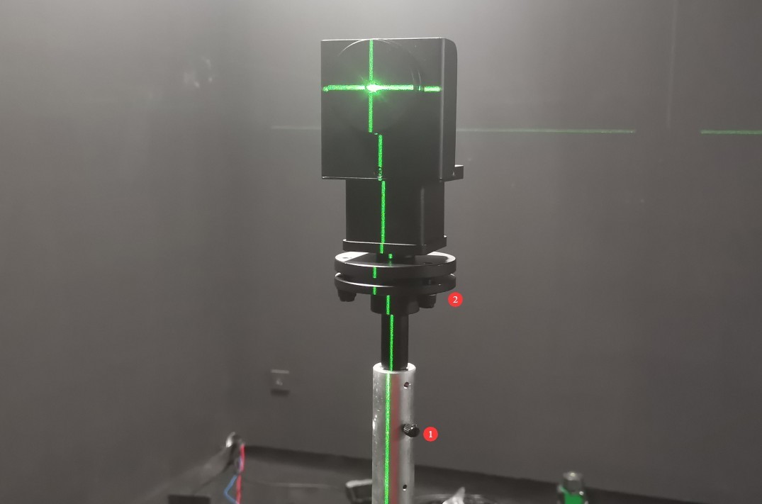
Gambar 64
Lampu standar harus disesuaikan sehingga berkas laser berbentuk salib diarahkan ke tengah cermin kecil, dan berkas laser horizontal dan vertikal yang dipantulkan dari cermin bertepatan persis dengan berkas laser berbentuk salib aslinya.
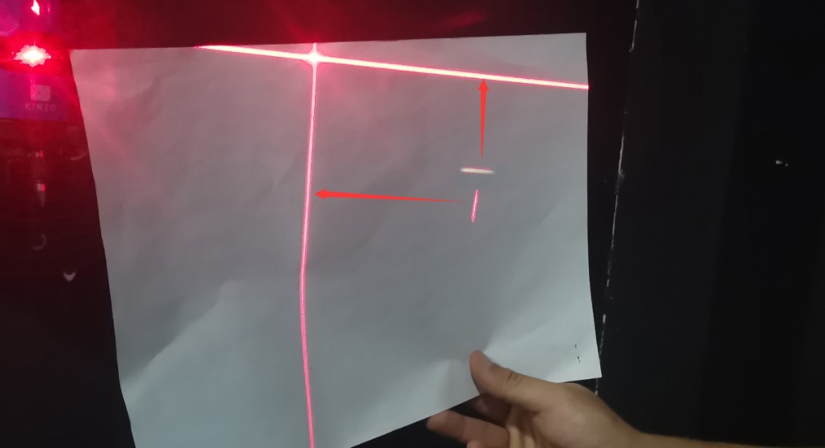
Gambar 65
Based on our experience, follow these steps for calibration: First, adjust the height of the reference lamp to the appropriate position. The vertical reflected laser can be calibrated by rotating the calibration target, while the horizontal reflected laser can be calibrated by adjusting the pitch of the reference lamp. After calibration, the center height of the reference lamp may change, requiring further adjustment of its height. Continue the reflection adjustment until the cross-shaped laser beam is projected onto the center of the small mirror, and the horizontal and vertical reflected laser beams perfectly align with the original cross-shaped laser beam.
Once the standard lamp is properly aligned, carefully remove the small reflector, taking care not to alter the alignment of the standard lamp while doing so. Then turn off the cross-hair laser.
6.2 Kalibrasi Probe Fotometri
Semua lampu standar adalah sumber cahaya DC arus konstan. Atur sakelar AC/DC pada Kabinet Instrumen Standar 19 inci ke DC.
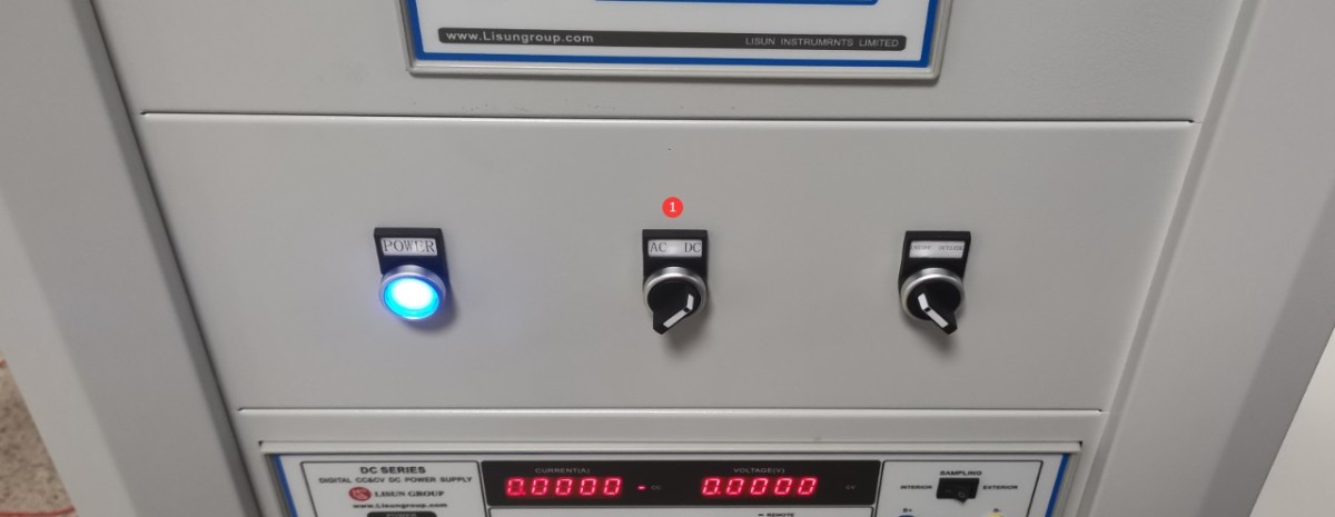
Gambar 66
Buka pengontrol sudut perangkat lunak.
| Jumlah | Note |
| ① | Gamma Angle Selection for Near-Field Photometric Probes |
| ② | Masukkan -90 |
| ③ | Click to rotate the Gamma axis to the -90-degree position (if the crosshair laser is installed in a different position on your darkroom drawing, you will need to rotate it to the 90-degree position). |
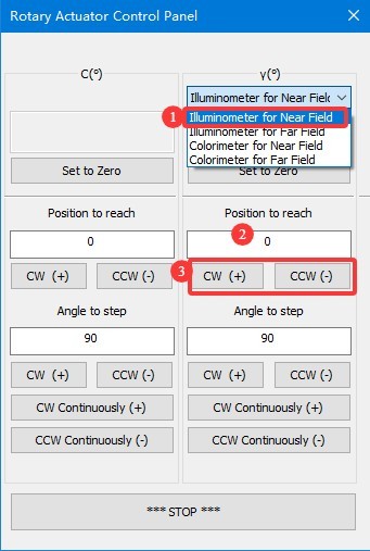
Gambar 66.1
Align the round hole in the standard lamp mount so that it faces the photometric probe.
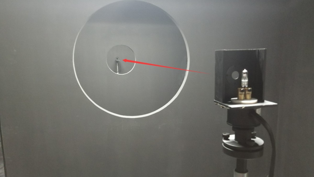
Gambar 67
Turn on the calibration lamp and enter the calibration interface.
| Jumlah | Note |
| ① | Pilih Catu Daya DC |
| ② | The standard lamp is a constant-current light source. Select CC (constant-current mode) and enter the reference voltage and rated current as specified in the standard lamp certificate; typically, these are 30 V and 6.1 A. |
| ③ | Klik untuk menyalakan lampu standar dan mematikan semua lampu lain di ruang gelap. Lampu standar membutuhkan waktu 15 menit untuk mencapai kondisi stabil. |
| ④ | Once the standard lamp has stabilized, click to enter the photometric probe calibration interface. |
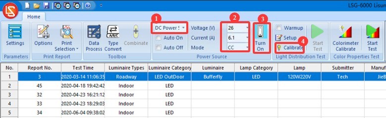
Gambar 68
Close the darkroom door and make sure that all light sources in the darkroom are turned off, except for the standard lamp.
| Jumlah | Note |
| ① | Memilih Probe Fotometri Medan Dekat |
| ② | Luminous flux calibration—our software includes this option, but current industry standards require the use of luminous intensity calibration, and the standard lamp included in our standard configuration is also a luminous intensity standard lamp. Therefore, there is no need to use luminous flux calibration at this time. |
| ③ | Metode Kalibrasi Intensitas Cahaya |
| ④ | Rujuklah pada sertifikat kalibrasi lampu standar dan masukkan nilai intensitas cahaya yang telah dikalibrasi. |
| ⑤ | Klik untuk Memulai |
| ⑥ | Perangkat lunak akan secara otomatis menghitung jarak uji. |
| ⑦ | To reconfirm, click “Check,” and the software will display the current measured light intensity. The measured light intensity should match the calibrated light intensity. |
| ⑧ | Klik “OK” untuk menyimpan dan keluar. |
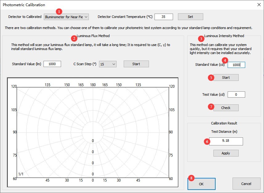
Gambar 69
Note: The test distance is the distance from the center of the Goniophotomoeter to the surface of the photometric probe. The distance calculated by the software should be close to the actual distance; an error of 1% or less is considered normal. If the error is too large, please refer to Section 2.3.1 to verify that the darkroom is functioning properly, and refer to Chapter 5 to review the calibration steps.
6.3 Calibration of Spectroradiometers
The reference lamp remains lit and stable. Enter the angle control interface.
| Jumlah | Note |
| ① | Gamma-Angle-Selective Near-Field Spectroradiometer |
| ② | Masukkan -90 |
| ③ | Click to rotate the Gamma axis to the -90-degree position (if the crosshair laser is installed at a different position in your darkroom drawings, you will need to rotate it to the 90-degree position). |
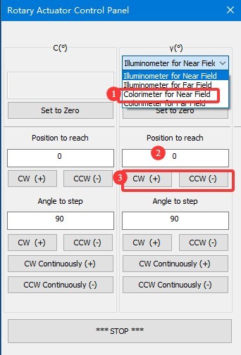
Gambar 70
Align the round hole in the standard lamp mount directly toward the photometric probe.
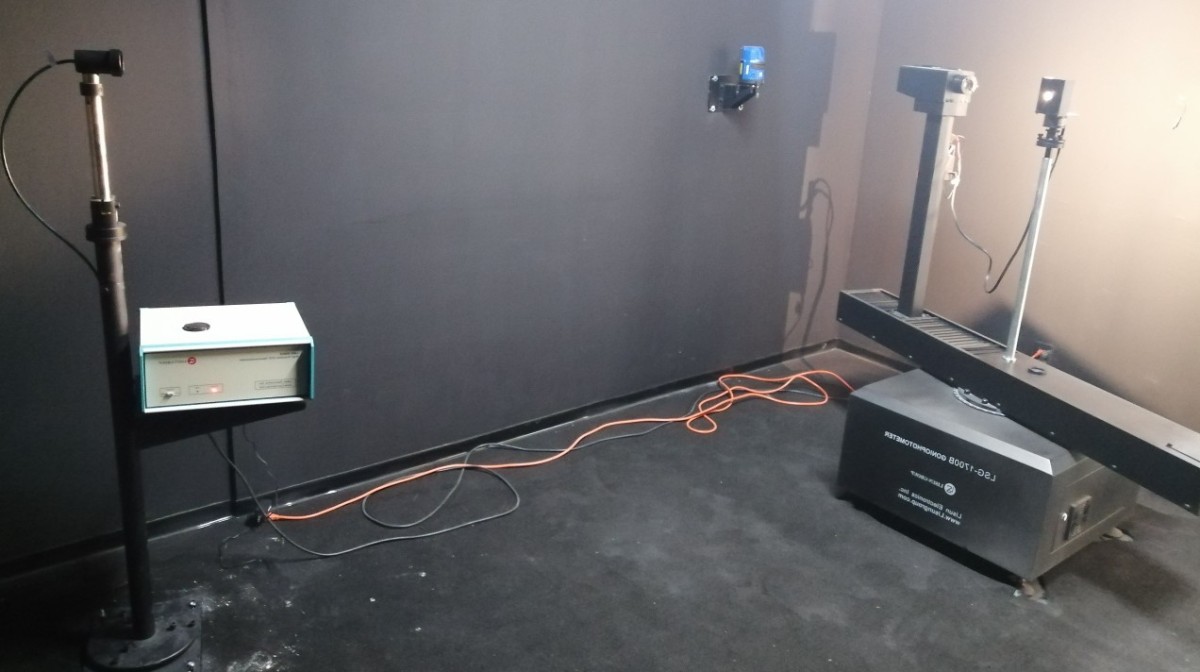
Gambar 71
Close the darkroom door and make sure that all light sources other than the standard lamp are turned off. Click to enter the Spectroradiometer calibration interface.
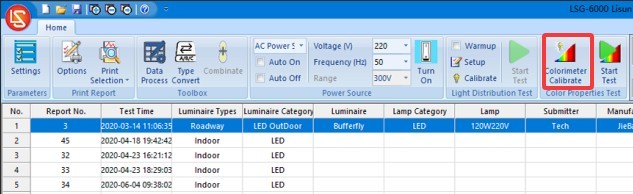
Gambar 72
| Jumlah | Note |
| ① | Untuk waktu pengumpulan poin, pastikan untuk selalu memilih “Otomatis.” |
| ② | First, click “Sampling.” Once sampling is complete, the corresponding curve will appear on the screen. After sampling is complete, the “Calibrate” button becomes clickable. |
| ③ | Refer to the standard lamp calibration certificate and enter the specified color temperature value. |
| ④ | Klik “Kalibrasi.” Setelah kalibrasi selesai, kurva yang sesuai akan muncul di layar. |
| ⑤ | Klik OK untuk menyimpan dan keluar. |
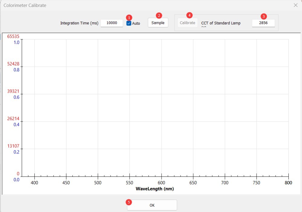
Gambar 73
After calibration is complete, you can turn off the standard lamp using the software. Since the standard lamp becomes quite hot during use, wait for it to cool down before placing it back in its packaging for safe storage. Remove the calibration rod and store it safely.
6.4 Kalibrasi dan Pemeliharaan
| Tidak ada perubahan di ruang gelap. | Jika tidak ada perubahan pada komputer, kalibrasi ulang tidak diperlukan. |
| No changes were made to the computer; simply unplug and replug the communication cable or reinstall the Goniophotomoeter software—no recalibration is necessary. | |
| If you replace your computer or reinstall the operating system, the photometric probe does not need to be recalibrated; simply enter the previous test distance and save it. However, the Spectroradiometer does need to be recalibrated (if you are unable to perform recalibration, please contact us to restore the calibration data). | |
| Perubahan di Ruang Gelap | Struktur ruang gelap tetap tidak berubah; namun, setelah penggunaan yang lama, cat interior dapat memudar atau mengelupas. Tergantung pada seberapa baik Anda merawat ruang gelap dan tingkat akurasi yang Anda perlukan untuk hasil pengujian Anda, Anda mungkin perlu mengecat ulang ruang gelap secara berkala. Setelah pengecatan ulang, ruang gelap harus dikalibrasi ulang. |
| Terdapat perubahan pada konfigurasi ruang gelap, sehingga diperlukan kalibrasi ulang. |
7. Persiapan Sebelum Pengujian
7.1 Luminaire Selection and Aging
Pilih luminer representatif untuk pengujian yang sesuai dengan standar nasional atau perusahaan; luminer baru harus menjalani perawatan penuaan (untuk luminer LED, periode penuaan 24 jam disarankan);
Check that the light fixture has no visible damage, that the internal wiring is connected correctly, and clean any stains from the surface of the light fixture.
7.2 Introduction to Test Mode
Mode C-Gamma: Cocok untuk sebagian besar perlengkapan pencahayaan, seperti lampu jalan, lampu downlight, lampu panel, dan lampu pertumbuhan tanaman.
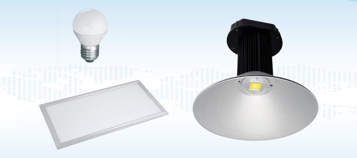
Gambar 74
Mode Beta: Cocok untuk lampu sorot, lampu banjir, dan perlengkapan serupa; memerlukan pemasangan lengan tambahan.
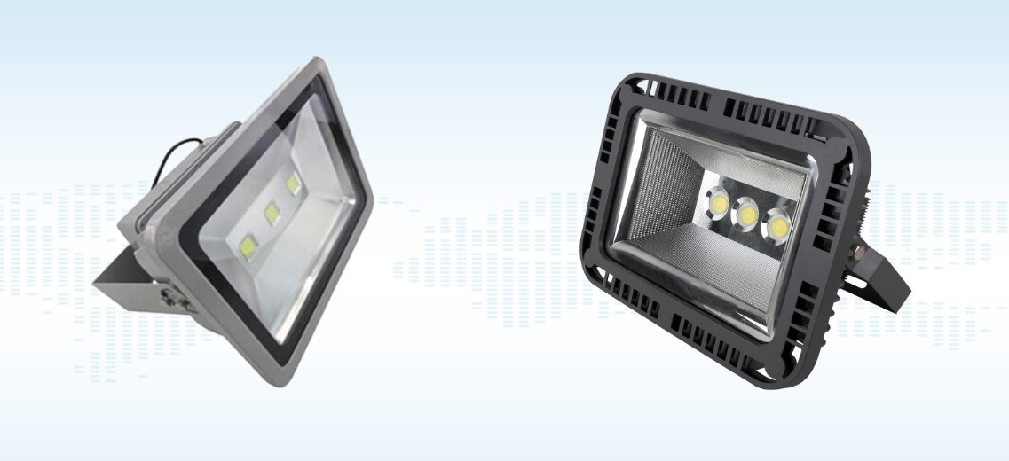
Gambar 75
Mode Alpha: Cocok untuk lampu otomotif dan lampu sein.
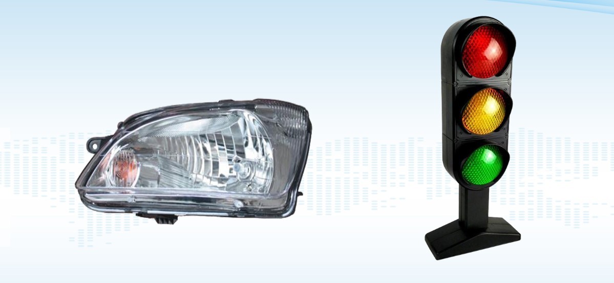
Gambar 76
Catatan: LSG-1800ACCD can perform C-Gamma and B-Beta tests. For A-Alpha testing, a Type A goniophotomoeter is required; please contact us if needed.
8. Tes C-Gamma
8.1 Uji Distribusi Intensitas Cahaya
8.1.1 Memasang dan Menyalakan Perlengkapan Lampu
8.1.1.1 Lighting Fixture Installation
We have two C-Gamma test fixtures; these operating instructions use the cross-shaped fixture as an example.
| Jumlah | Note |
| ① | Penjepit berbentuk salib berukuran besar digunakan untuk berbagai jenis perlengkapan pencahayaan. |
| ② | Fitting E27 untuk Pengujian Bohlam Bola |
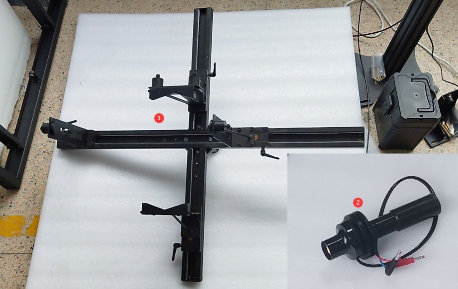
Gambar 77
Attach the fixture to the Goniophotomoeter. Turn on the wall-mounted cross-line laser and verify that the cross-line laser is projected accurately onto the marks made on the opposite wall.
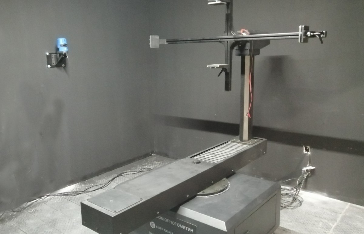
Gambar 78
On the angle control interface, select the near-field photometric probe. Rotate the Gamma axis 90 degrees so that the crosshair laser points directly at the center of the crosshair fixture. Mount the luminaire under test onto the crosshair fixture. Adjust the position of the luminaire so that the crosshair laser is centered on the light-emitting surface of the luminaire under test, and ensure that the light-emitting surface is parallel to the crosshair fixture.
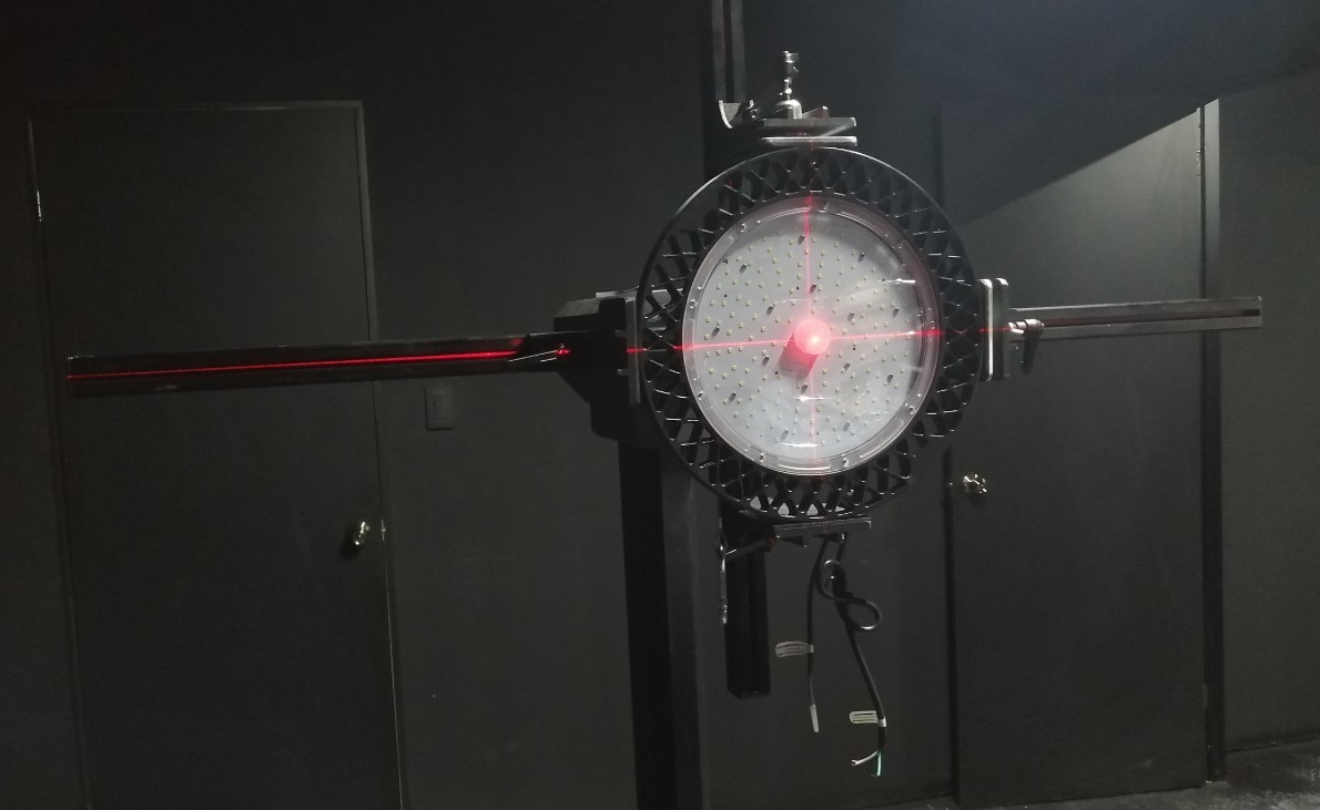
Gambar 79
Then rotate the Gamma axis back to 0 degrees. Loosen this screw by turning it counterclockwise.
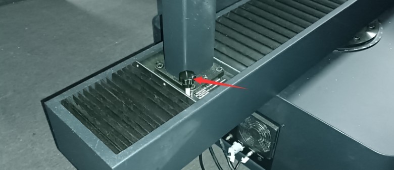
Gambar 80
Move the spindle so that the light-emitting surface of the fixture aligns with the vertical laser beam of the crosshair, and then tighten the screw clockwise.
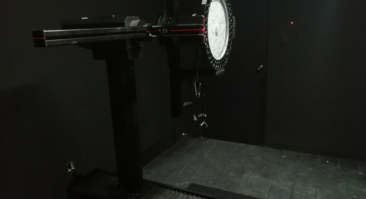
Gambar 81
Caution is required when installing directional luminaires. When the angle of the C-plane on the Goniophotomoeter is 0 degrees, according to streetlight installation standards, the light pole should be oriented straight upward, as shown in the figure below.
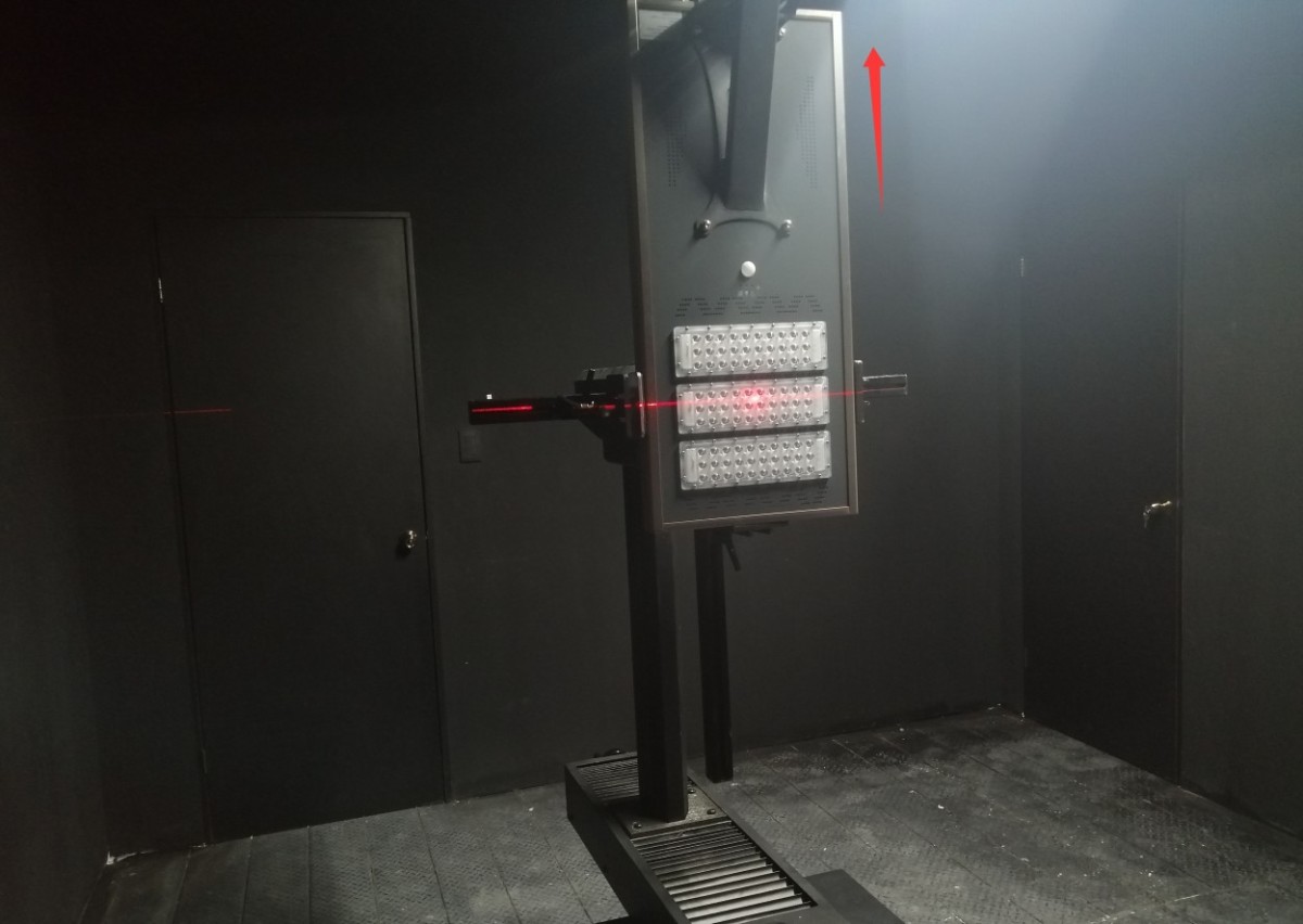
Gambar 81.1
When the angle of the C-plane on the goniophotomoeter is 0 degrees, the strip light should be installed vertically in accordance with industry standards, as shown in the figure below.
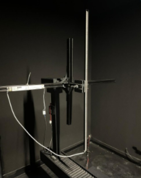
Gambar 81.2
8.1.1.2 Menyalakan Lampu
Connect the power cord to the luminaire under test. The connection method for the luminaire under test is the same as that for the standard luminaire; refer to 6.1.1.
Sesuaikan sakelar kabinet sesuai dengan parameter luminer yang sedang diuji.
| Jumlah | Note |
| ① | If the sample luminaire is powered by AC, switch to the AC direction; if it is powered by DC, switch to the DC direction. |
| ② | Internal/External Sampling Switch for Electrical Parameters. External sampling uses a four-wire configuration and provides more accurate voltage readings. Unless otherwise specified, set this switch to “External Sampling”; no further adjustments are necessary. |
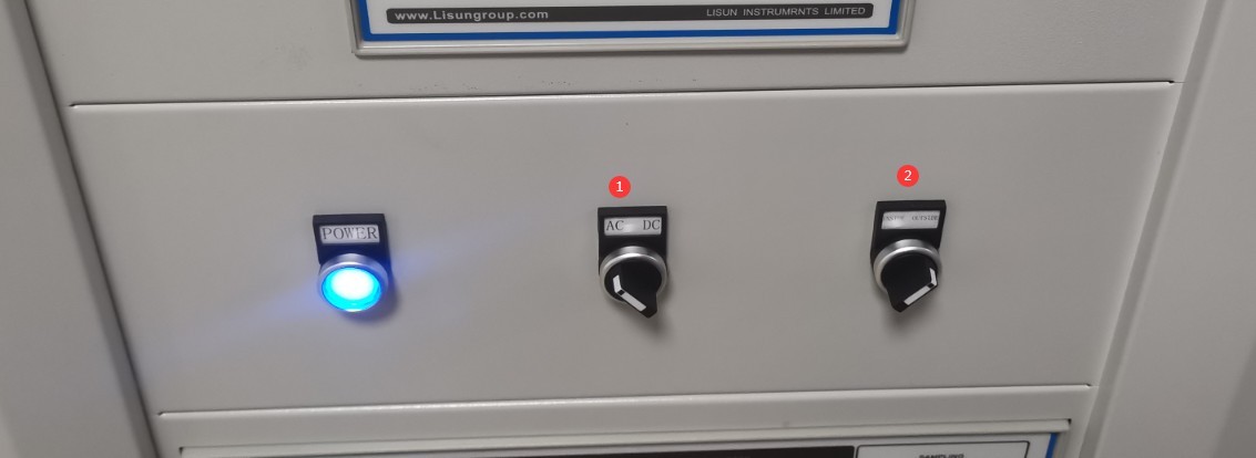
Gambar 82
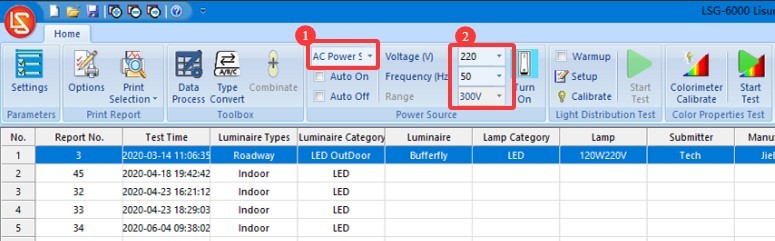
Jika lampu sampel menggunakan daya AC.
| Jumlah | Note |
| ① | Pilih Daya AC |
| ② | Berdasarkan parameter sampel, masukkan tegangan dan frekuensi yang benar. |
Gambar 83
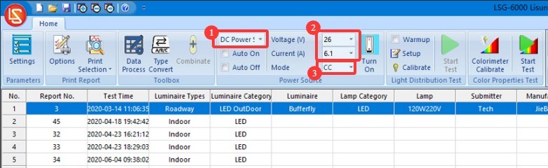
Jika lampu sampel menggunakan daya DC.
| Jumlah | Note |
| ① | Pilih Catu Daya DC |
| ② | Berdasarkan parameter sampel, masukkan tegangan dan arus yang benar. |
| ③ | Select the output mode: CC stands for constant current, and CV stands for constant voltage. If you select constant current, you need to enter the sample’s rated current value; for the voltage, simply enter the maximum output voltage of this DC power supply. If you select constant voltage, enter the sample’s rated voltage and the DC power supply’s maximum output current. Catatan: Jika model catu daya DC Anda adalah DC3010, its maximum output voltage is 30V and its maximum output current is 10A. |
Gambar 84
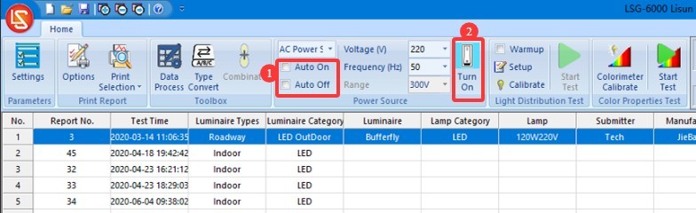
The software offers two methods for turning the sample lamp on and off, and users can choose between them.
| Jumlah | Note |
| ① | If you check the “Auto Turn On” and “Auto Turn Off” options, the software will automatically turn on the sample using the selected power source and the entered electrical parameters when the test begins, and will automatically cut off the sample’s power when the test ends. |
| ② | If the “Auto On” and “Auto Off” options are not checked, you can still click this button; the software will turn on the sample based on the selected power source and the entered electrical parameters. Clicking this button again will turn off the sample’s power. |
Gambar 85
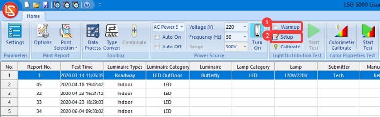
8.1.2 Pengaturan Parameter Pemanasan Awal
| Jumlah | Note |
| ① | If you check the “Preheat” box, the software will preheat the luminaires according to the specified preheat parameters when the test begins, and the test will start automatically once preheating is complete. If you do not check the “Preheat” box, the software will begin the test immediately. |
| ② | Pengaturan Parameter Pemanasan Awal |
Gambar 86
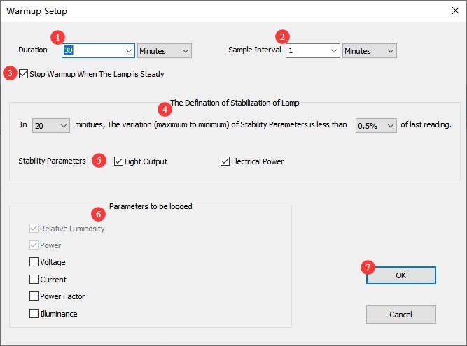
Click “Preheating Parameter Settings.”
| Jumlah | Note |
| ① | Pengaturan Durasi Pemanasan: Tujuan dari pemanasan adalah untuk memungkinkan perlengkapan lampu tetap menyala selama jangka waktu tertentu hingga parameter cahaya dan warnanya stabil, setelah itu pengujian akan dilanjutkan secara otomatis. |
| ② | Interval pengambilan sampel: Perangkat lunak akan secara otomatis mengambil sampel pada interval yang telah ditetapkan selama seluruh periode pemanasan untuk mendapatkan data waktu nyata. Kami merekomendasikan untuk mengatur interval menjadi 5 detik atau lebih lama. |
| ③ | If checked, the test will automatically skip the remaining warm-up time and begin once the light fixture reaches a stable state; if unchecked, the test will begin only after the warm-up period has been completed according to the set duration. |
| ④ | Definition of a luminaire’s steady state. If set to 20 and 0.5%, the luminaire is considered to be in a steady state if the parameter has not varied by more than 0.5% over the past 20 minutes. |
| ⑤ | Anda dapat memilih parameter mana yang harus digunakan perangkat lunak untuk menentukan apakah perlengkapan lampu stabil: parameter optik, parameter listrik. |
| ⑥ | Perangkat lunak akan menyimpan kurva perubahan untuk parameter yang dipilih selama periode pemanasan dalam laporan pengujian. |
| ⑦ | Setelah Anda selesai mengkonfigurasi pengaturan, klik OK untuk menyimpan dan keluar. |
Gambar 87
8.1.3 Mengonfigurasi Parameter Pengujian dan Memulai Pengujian
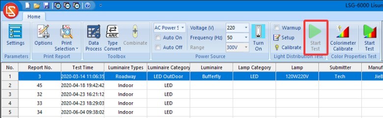
Klik “Mulai Tes.”
Gambar 88
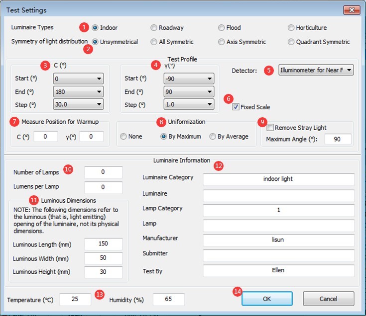
Buka layar pengaturan parameter pengujian.
| Jumlah | Note |
| ① | Jenis perlengkapan pencahayaan: lampu dalam ruangan, lampu luar ruangan, atau lampu pertumbuhan tanaman—ketiga jenis perlengkapan pencahayaan ini tunduk pada pengujian C-Gamma. |
| ② | Select whether the luminaire is symmetrical. Unless otherwise specified, select the first option, “asymmetrical,” regardless of whether the luminaire being tested is symmetrical or not (to obtain the luminaire’s actual data). |
| ③ | Rentang sudut bidang C: Pilih 0 hingga 180 derajat; tidak perlu modifikasi. Untuk data yang berkisar dari 180 hingga 360 derajat, perangkat lunak akan secara otomatis mengonversinya. C-plane angle intervals. For symmetrical fixtures, such as indoor lights, you can select a larger interval, such as 30 degrees; for asymmetrical fixtures, such as streetlights, you can select a smaller interval, such as 10 degrees. The smaller the angle interval, the higher the testing accuracy, but the longer the testing time. If time permits, it is recommended to select a smaller angle interval. |
| ④ | Gamma plane angle range: If the sample’s illumination angle exceeds 180 degrees (e.g., a globe lamp), select -180 degrees to 180 degrees; if the sample’s illumination angle is less than 180 degrees (e.g., a panel light), you may select a Gamma plane angle interval of -90 degrees to 90 degrees. Unless there are special requirements, selecting 1 degree is sufficient. Different angle intervals here have no effect on test speed. |
| ⑤ | If the system has multiple photometric probes, please select the one you want to use. |
| ⑥ | Fixed Range: If you are consistently measuring the same type of light—and the luminous intensity data does not vary significantly—you can check this box to save time. However, if you have ample time or frequently test lights with varying luminous intensities, we recommend leaving this box unchecked so that the photometer can automatically select the appropriate range for each light. |
| ⑦ | Untuk mengatur sudut pemantauan selama fase pemanasan lampu, cukup atur ke (0, 0). |
| ⑧ | Normalization refers to the decision of whether to apply a uniform value to the first row of data in the luminous intensity table of a test report; certain standards, such as the U. S. streetlight standard, may require you to perform this type of adjustment. There are three options: no normalization, normalization to the maximum value (which slightly increases the luminaire’s total luminous flux), and normalization to the average value (which leaves the luminous flux essentially unchanged). |
| ⑨ | If you need to remove all stray light outside a specific angle, check this box and enter the desired angle . For example, if you check this box and enter 60, the data outside ±60 degrees of the luminaire’s gamma plane will automatically be set to 0. |
| ⑩ | Enter the number of light sources in the luminaire and the rated luminous flux of each light source. If you do not know this information, you may leave it blank; it will not affect the test results. |
| ⑪ | Masukkan dimensi permukaan pemancar cahaya sampel. Untuk perlengkapan pencahayaan dalam ruangan, perangkat lunak memerlukan data ini untuk menghitung kurva batas luminansi, UGR, dan parameter lainnya. |
| 1 | Masukkan informasi tentang contoh lampu penerangan. |
| ⑬ | Enter the temperature and humidity of the test environment (i.e., the darkroom) |
| ⑭ | Click OK to go to the warm-up screen, or to the test screen. |
Gambar 89
Then wait for the software test to complete. Once the test is complete, refer to Section 8.2 to perform the chromaticity distribution test.
8.2 Uji Distribusi Kromatisitas
After completing the C-Gamma luminous intensity distribution test, you can conduct a chromaticity distribution test based on the test report.
Note: The software automatically calculates the spatial angle range required for the chromaticity distribution test based on the photometric distribution test report. Therefore, if a photometric distribution test is not performed, a chromaticity distribution test cannot be conducted directly.
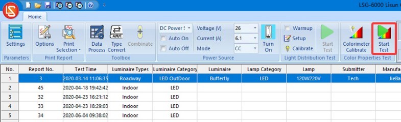
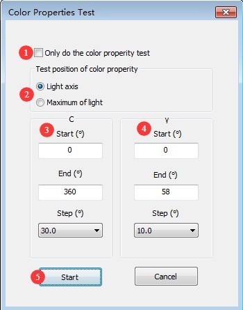
Pilih laporan uji distribusi fotometrik untuk luminer ini, lalu klik untuk membuka antarmuka pengaturan parameter uji distribusi kromatisitas.
Gambar 90
| Jumlah | Note |
| ① | Jika dicentang, hanya uji karakteristik kromatisitas yang akan dilakukan; uji distribusi kromatisitas tidak akan dilakukan. Jika tidak dicentang, baik uji karakteristik kromatisitas maupun uji distribusi kromatisitas akan dilakukan. |
| ② | Selection of test positions for colorimetric characteristics. The “optical axis” refers to the position directly in front of the light-emitting surface of the sample luminaire; the “point of maximum luminous intensity” refers to the position where the luminous intensity of the sample luminaire is highest. |
| ③ | Rentang sudut untuk bidang C adalah 0 hingga 360 derajat. Tidak perlu melakukan penyesuaian. the angle increment for the C-plane. For symmetrical fixtures, such as indoor lights, a larger increment—for example, 30 degrees—can be selected, while for asymmetrical fixtures, such as streetlights, a smaller increment—for example, 10 degrees—can be chosen. The smaller the increment, the higher the testing accuracy, but the longer the testing time. |
| ④ | The gamma plane angle range is automatically calculated by the software based on the results of the photometric distribution test. There is no need to adjust the angle intervals of the gamma plane. You may also choose a wider angle interval; symmetrical luminaires, such as indoor lights, can use a wider interval—for example, 10 degrees—while asymmetrical luminaires, such as streetlights, can use a narrower interval—for example, 5 degrees. The smaller the angle interval, the higher the test accuracy; however, the test will take longer. |
| ⑤ | Setelah Anda selesai melakukan pengaturan, klik “Mulai” untuk memulai pengujian, dan tunggu hingga perangkat lunak secara otomatis menyelesaikan pengujian mandiri. |
Gambar 91
9. Pengujian B-Beta
9.1 Uji Distribusi Intensitas Cahaya
9.1.1 Memasang dan Menyalakan Perlengkapan Lampu
9.1.1.1 Pemasangan Perlengkapan Lampu
Turn on the crosshair laser and make sure it is still shining on the mark you made on the opposite wall.
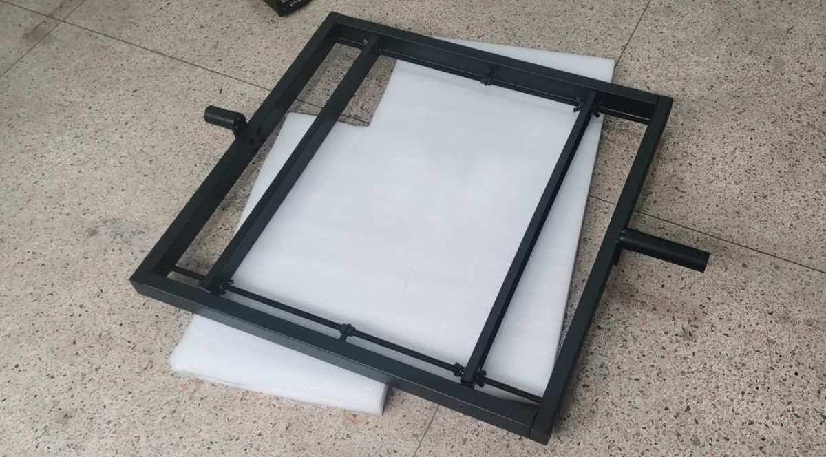
Find the square B-Beta test fixture.
Gambar 92
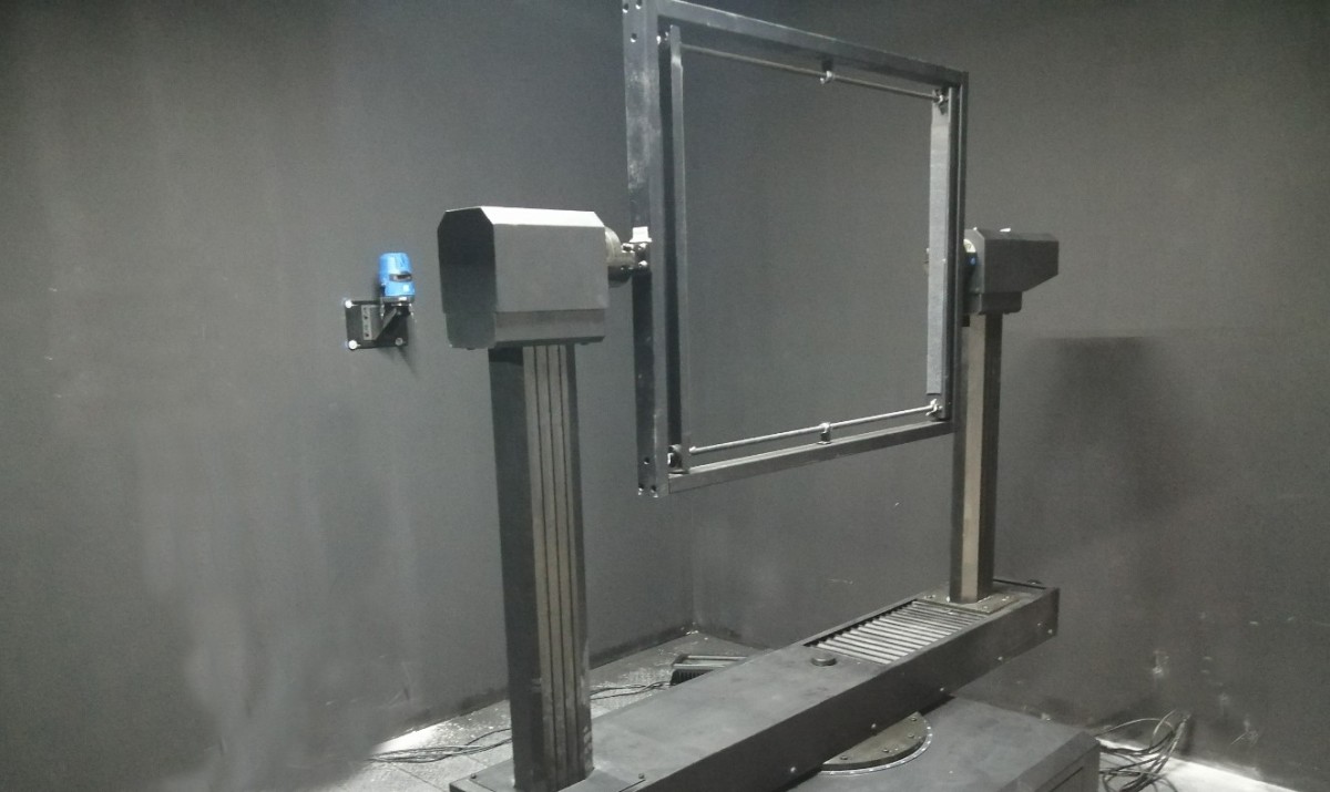
When performing the B-Beta test, reattach the auxiliary arm of the Goniophotomoeter. Then, install the B-Beta fixture vertically as shown in the figure.
Gambar 93
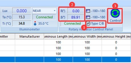
| Jumlah | Note |
| ① | Click to switch the angle display mode |
| ② | Klik ① untuk menampilkan sudut B-Beta di sini, bukan sudut C-Gamma. |
| ③ | Klik untuk membuka antarmuka kontrol sudut. |
Gambar 94
| Jumlah | Note |
| ① | When angle B is 0 degrees, the fixture should be in a vertical position; this can be verified using a level. |
| ② | Masukkan 0 |
| ③ | Click to set the Beta angle to 0 degrees. Note: The 0-degree position for the Gamma angle is not the same as the 0-degree position for the Beta angle. |
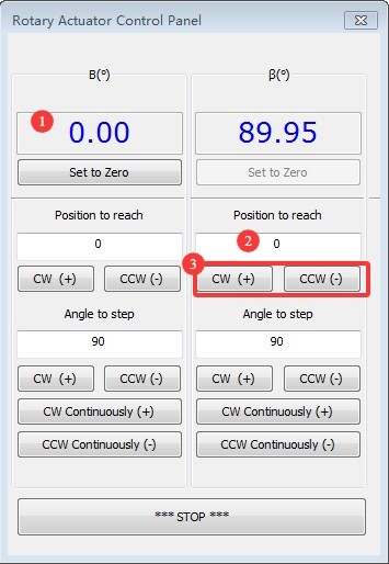
Gambar 95
After rotating Beta to the 0-degree position, mount the floodlight onto the fixture so that its light-emitting surface faces the photometric probe. Adjust the fixture’s mounting position so that the cross-shaped vertical laser beam aligns with the light-emitting surface of the fixture.
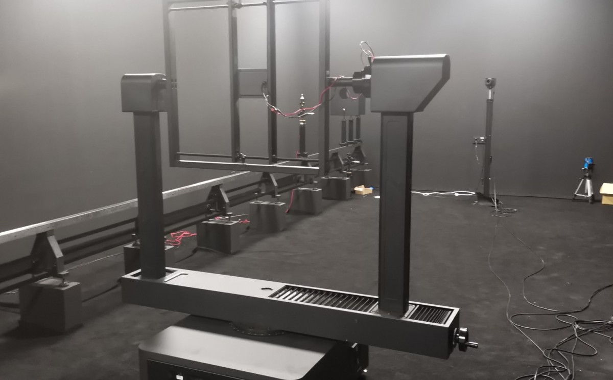
Gambar 96
To ensure that the sample is positioned exactly in the center of the Goniophotomoeter, rotate the Beta fixture to the position shown in the figure below so that the sample’s light-emitting surface faces the crosshairs. Use the crosshairs to fine-tune the sample holder’s position.
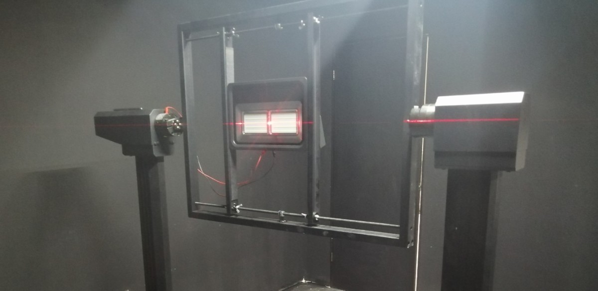
Gambar 97
Setelah perlengkapan lampu terpasang, Anda dapat mematikan laser garis silang.
9.1.1.2 Menyalakan Lampu
Please refer to 8.1.1.2.
9.1.2 Pengaturan Parameter Pemanasan Awal
Please refer to 8.1.2.
9.1.3 Mengonfigurasi Parameter Pengujian dan Memulai Pengujian
Klik “Mulai Pengujian” untuk menuju ke layar pengaturan parameter pengujian.
| Jumlah | Note |
| ① | Silakan pilih “Floodlight,” dan mode pengujian akan secara otomatis beralih ke B-Beta. |
| ② | Rentang sudut untuk Bidang B adalah -90 derajat hingga 90 derajat. Tidak perlu melakukan penyesuaian. the angle increment for Plane B; you can select a smaller increment, such as 5 degrees or 10 degrees. The smaller the increment, the higher the test accuracy, but the longer the test takes. |
| ③ | The Beta plane angle range is -90 degrees to 90 degrees. There is no need to adjust the angle interval for the Beta plane; unless there are special requirements, select 1 degree. Different angle intervals here have no effect on test speed. |
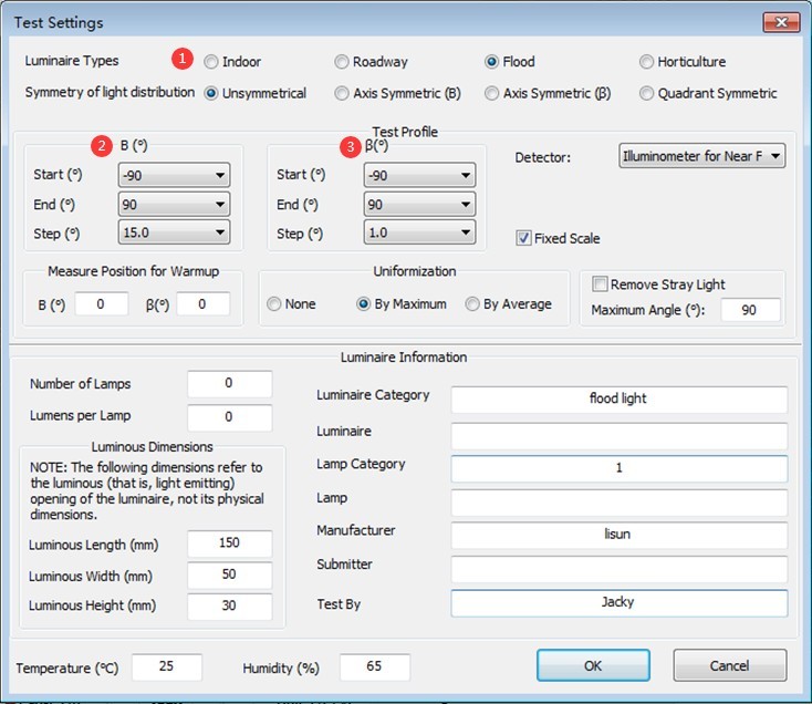
Gambar 98
Untuk pengaturan parameter lainnya, lihat Bagian 8.1.3. Setelah pengaturan dikonfigurasi, klik “Mulai” dan tunggu hingga perangkat lunak menyelesaikan pengujian. Setelah pengujian selesai, lihat Bagian 9.2 untuk melakukan pengujian distribusi kromatisitas.
9.2 Uji Distribusi Kromatisitas
After completing the B-Beta photometric distribution test, a chromaticity distribution test can be conducted based on the test report.
Pilih laporan uji distribusi fotometrik untuk luminer ini, lalu klik untuk membuka antarmuka pengaturan parameter uji distribusi kromatisitas.
| Jumlah | Note |
| ① | The angle range for Plane B is automatically calculated by the software based on the results of the photometric distribution test; there is no need to adjust the angle interval for Plane B. Options include, for example, 5 degrees and 10 degrees. The smaller the interval, the higher the test accuracy, but the longer the test takes. |
| ② | Rentang sudut bidang beta dihitung secara otomatis oleh perangkat lunak berdasarkan hasil uji distribusi fotometrik; tidak perlu melakukan penyesuaian. Interval sudut bidang beta, yang dapat diatur ke nilai-nilai seperti 5 derajat atau 10 derajat. Semakin kecil intervalnya, semakin tinggi akurasi pengujian, tetapi semakin lama waktu yang dibutuhkan untuk pengujian. |
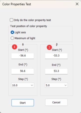
Gambar 99
For other parameter settings, refer to Section 8.2. Once you have configured the settings, click “Start” and wait for the software to complete the test automatically.
10. Pemrosesan Laporan Tes
10.1 Mengorganisasi File Basis Data
| Jumlah | Note |
| ① | By default, all test reports are automatically stored in the currently open database file in the order in which the tests were performed. |
| ② | Untuk menghapus laporan, pilih laporan tersebut lalu klik “Hapus.” |
| ③ | Untuk mempermudah pencarian laporan pengujian, klik tombol kosong yang ditunjukkan pada gambar di bawah untuk membuat file basis data baru, dan simpan laporan untuk berbagai luminer dalam file basis data terpisah. Setelah membuat file basis data baru, Anda dapat langsung melanjutkan pengujian tanpa perlu melakukan kalibrasi ulang atau konfigurasi ulang sistem. |
| ④ | Klik “Buka” untuk melihat laporan pengujian dari file basis data lainnya. |
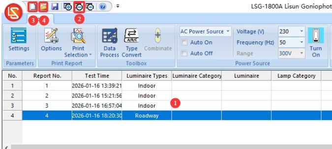
Gambar 100
Catatan 1: Saat perangkat lunak dibuka kembali, perangkat lunak akan secara otomatis memuat file basis data yang digunakan terakhir kali. Jika jalur ke file basis data tersebut telah berubah atau namanya telah dimodifikasi, perangkat lunak akan meminta Anda untuk membuat file basis data baru.
Catatan 2: Sebisa mungkin hindari menempatkan file basis data di desktop komputer Anda.
10.2 Pengaturan Tampilan Laporan Pengujian
| Jumlah | Note |
| ① | Anda dapat mengklik dua kali untuk mengunggah gambar perlengkapan lampu. |
| ② | Anda dapat mengklik dua kali konten yang ditampilkan di area ini untuk mengeditnya. |
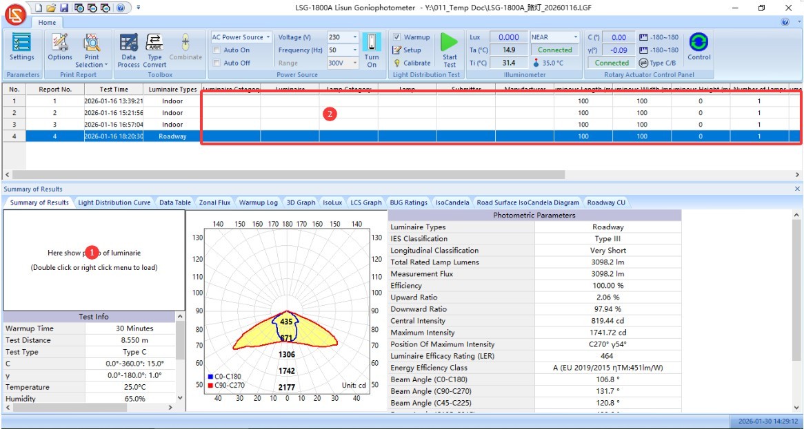
Gambar 101
| Jumlah | Note |
| ① | Klik "Pengaturan" |
| ② | For unit selection, “cd” is generally used; however, some older standards—such as those regarding energy-saving lamps—may require the use of “cd/klm.” |
| ③ | Streetlight C0 angle setting. The CIE/GB and IESNA standards have inconsistent requirements; please select the standard you are following. |
| ④ | Customize the divergence angle. The software automatically displays the half-peak angle (commonly referred to as the beam angle, calculated as 50% of the maximum luminous intensity) and the effective beam angle (calculated as 10% of the maximum luminous intensity). If you wish to customize the divergence angle, enter a percentage of the maximum intensity and check the box (e.g., 0.25 for 25%). In this case, the test report will display not only the half-peak angle and effective beam angle but also your custom divergence angle. |
| ⑤ | Centang kotak ini untuk menampilkan sudut kerucut intensitas cahaya maksimum dalam laporan. |
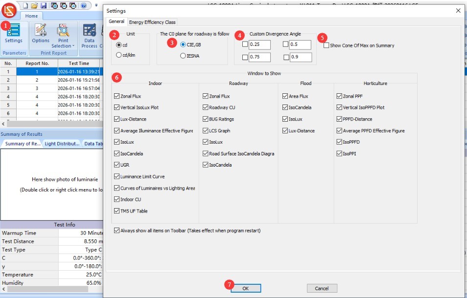
Gambar 102
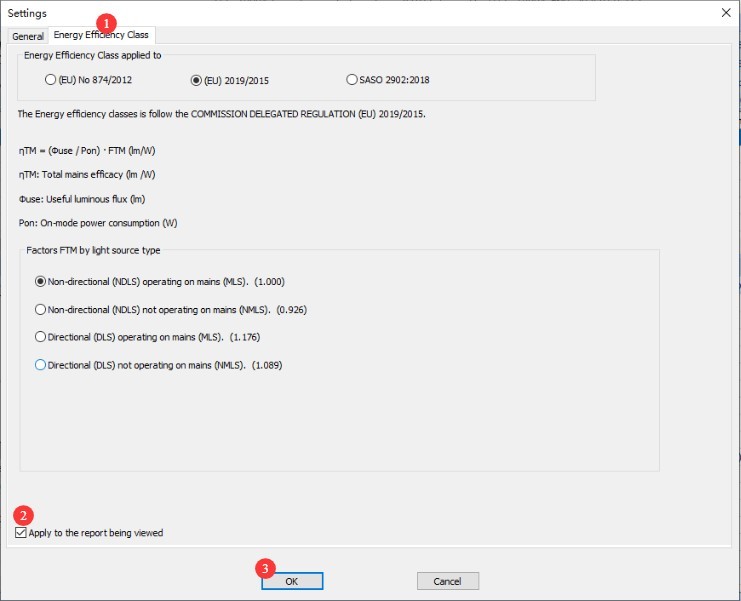
| Jumlah | Note |
| ① | Beralihlah ke layar pengaturan “Peringkat Efisiensi Energi”, lalu pilih standar dan jenis luminer yang sesuai. |
| ② | Klik untuk menerapkan pada laporan tes saat ini |
| ③ | Klik OK untuk menyimpan dan keluar. |
Gambar 103
Each display window has several settings that allow you to customize the display. Users are encouraged to experiment with these settings to adjust the display as desired.
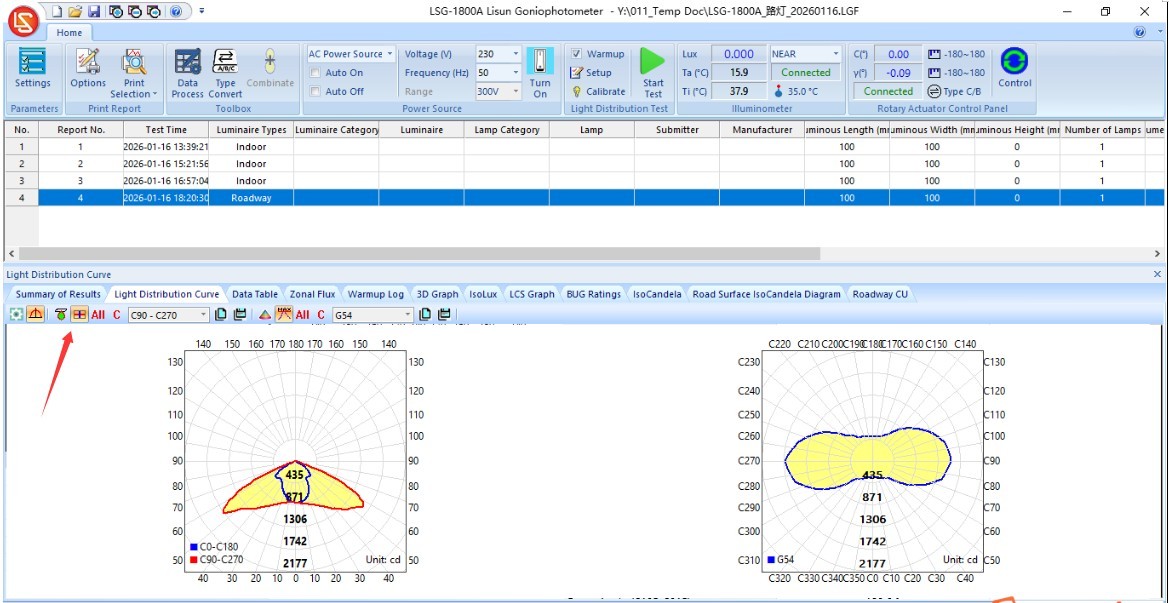
Gambar 103.1
10.3 Memproses Data Uji
10.3.1 Double-Sided Luminaires
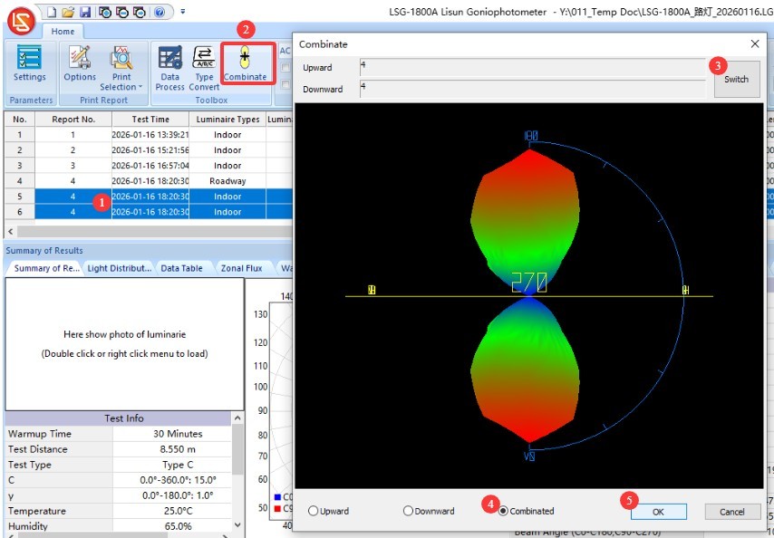
For lamps that emit light from both sides, use the indoor lamp test mode to test each side individually—that is, set the gamma plane angle range to -90 degrees to 90 degrees during testing—and then generate two test reports.
| Jumlah | Note |
| ① | Hold down the “Ctrl” key on your keyboard, then click to select the two test reports you just received. |
| ② | Klik “Sintesis Data” di bilah navigasi perangkat lunak. |
| ③ | Di jendela pop-up, Anda dapat mengklik untuk beralih antara pancaran cahaya ke atas dan ke bawah. |
| ④ | Pilih “Komposit” |
| ⑤ | Klik OK untuk menyimpan dan keluar. |
Gambar 104
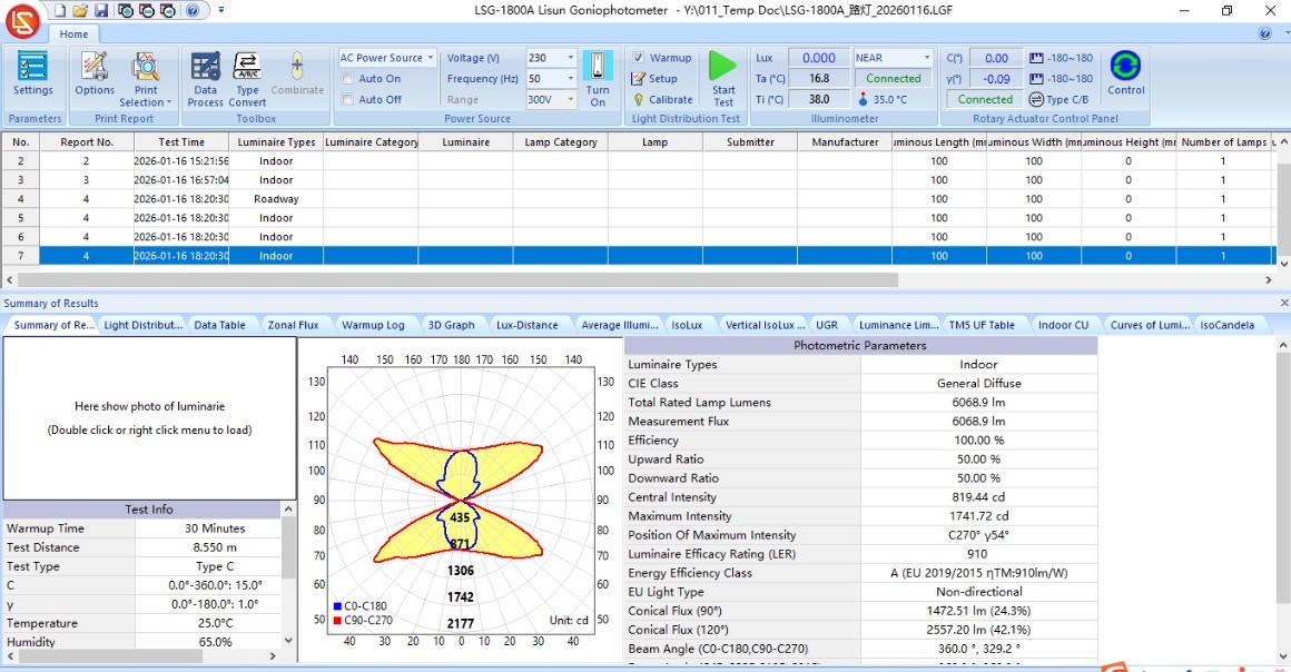
Ini akan menghasilkan laporan uji sintetis baru, seperti yang ditunjukkan pada gambar di bawah ini.
Gambar 105
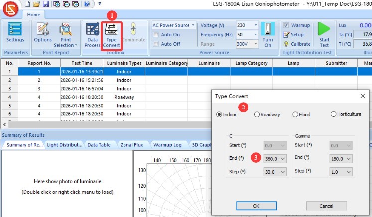
10.3.2 Conversion of Test Report Types
| Jumlah | Note |
| ① | Klik “Konversi Tipe” |
| ② | Test reports can be converted between four different types |
| ③ | When converting to a C-Gamma test report, you can use the “termination angle” in the C-plane to generate a symmetric test report. If the termination angle is set to 360 degrees, there will be no symmetry; if the termination angle is set to 180 degrees, the report can be converted to an axis-symmetric test report; if the termination angle is set to 90 degrees, the report can be converted into a quadrant-symmetric test report; if the termination angle is set to 0 degrees, the report can be converted into a fully symmetric test report. This feature is primarily intended for symmetric indoor lighting fixtures; certain lighting design software programs, such as DIALUX, may require you to use it when importing fully symmetric IES files. |
Gambar 106
10.4 Mengekspor Data Uji dan Mencetak Laporan Uji
10.4.1 Mengekspor Data Uji
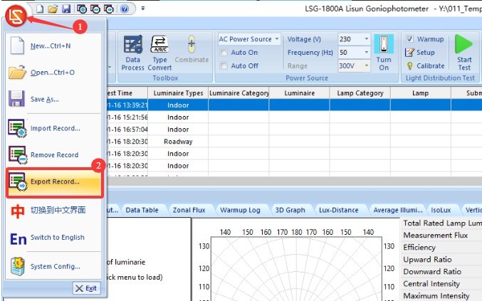
| Jumlah | Note |
| ① | Klik logo merah di pojok kiri atas perangkat lunak. |
| ② | Klik “Ekspor Data” di menu tarik-turun. |
Gambar 107
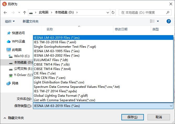
File dapat diekspor dalam berbagai format standar.
Gambar 108
10.4.2 Mencetak Laporan Uji
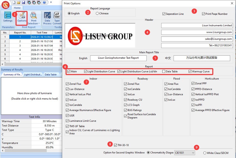
Pengaturan pencetakan.
| Jumlah | Note |
| ① | Klik untuk membuka layar “Pengaturan Cetak” |
| ② | Laporan ini menampilkan pilihan bahasa; Anda dapat memilih antara bahasa Mandarin dan bahasa Inggris. |
| ③ | Format Nomor Halaman |
| ④ | Informasi Header Laporan |
| ⑤ | Judul Laporan dalam Bahasa Mandarin dan Inggris |
| ⑥ | General Report Content, Applicable to Reports on All Types of Lighting Fixtures |
| ⑦ | Since indoor lights, streetlights, floodlights, and plant growth lights have different key parameters, the report content will vary accordingly. You can select the items you want to include in the report individually. |
| ⑧ | Opsi TM-30 |
| ⑨ | CIE color space diagram and SDCM color tolerance diagram—you can choose only one of them. |
Gambar 109
| Jumlah | Note |
| ① | Klik untuk mencetak laporan pengujian yang saat ini dipilih |
| ② | Klik untuk mencetak semua laporan pengujian dalam file basis data saat ini. |
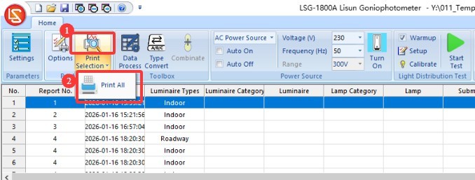
Gambar 110
11. Pemeliharaan dan Perawatan Peralatan Harian
11.1 Perawatan Rutin
Start-up procedure: First, turn on the cabinet’s main power switch; then, turn on the power switches for the equipment inside the cabinet and in the darkroom one by one; finally, launch the software. Shutdown procedure: First, close the software; then, turn off the power switches for the equipment inside the cabinet and in the darkroom one by one; finally, turn off the cabinet’s main power switch.
Jaga kebersihan dan bebas debu di ruang kontrol kamar gelap untuk mencegah debu masuk ke dalam peralatan. Jika ada debu di permukaan peralatan, bersihkan dengan kain kering dan lembut.
Hindari membiarkan ruang gelap terpapar kelembapan tinggi dalam waktu lama; sediakan alat pengering udara jika diperlukan.
11.2 Perawatan Rutin
11.2.1 Cleaning The Optical Fiber Of the Photometric Probe
If the darkroom cannot be kept dust-free, the photometric probe and the light-sensitive surface of the Optical Fiber should be cleaned regularly (for example, once a month) based on actual conditions to prevent dust from accumulating and affecting test accuracy.
When cleaning, please use a professional lint-free cloth to remove dust and prevent scratches on the device.
11.2.2 Standard Lamps
Lampu standar berlaku selama satu tahun. Jika Anda masih perlu mengkalibrasi ruang gelap setelah satu tahun, kami sarankan untuk membeli lampu standar yang baru.
Perangkat Lunak 11.2.3
We will release software updates from time to time to add features and fix bugs. If you encounter any issues while using the software, please feel free to contact us at any time to obtain the latest version.
11.3 Penonaktifan dan Pemeliharaan Jangka Panjang
11.3.1 Pembersihan dan Perlindungan Peralatan
Thoroughly clean all equipment surfaces, and cover the main unit, probes, spectrometer, and cabinet with dust-proof cloths; disconnect all power sources.
11.3.2 Perlindungan Lingkungan
Pastikan ruang gelap kering dan berventilasi baik untuk mencegah peralatan menjadi lembap. Jika kelembapan udara tinggi, sediakan alat pengering udara (dehumidifier).
11.3.3 Pengaktifan Daya Bulanan
Lakukan uji penyalaan daya sebulan sekali untuk memastikan semua perangkat keras sistem berfungsi dengan baik.
12. Pemecahan Masalah dan Penyelesaian Masalah Umum
12.1 Kesalahan Komunikasi
Penyebab masalah: Periksa apakah kabel komunikasi terhubung dengan aman dan tidak tercolok ke port yang salah; verifikasi bahwa driver telah terinstal dengan benar; coba port USB atau kabel komunikasi yang berbeda untuk mengesampingkan masalah perangkat keras.
Solusi: Instal ulang driver, sambungkan kabel komunikasi sesuai dengan pengenal perangkat, mulai ulang perangkat lunak, dan coba lagi.
12.2 Kesalahan Pengujian
12.2.1 Anomali Fluks Cahaya
Penyebab kerusakan: Periksa apakah sumber cahaya stabil dan apakah waktu pemanasan cukup; verifikasi bahwa kalibrasi peralatan valid, jarak pengujian benar, dan lampu standar berfungsi dengan baik; periksa apakah ada gangguan cahaya eksternal di ruang gelap dan apakah jalur cahaya terhalang.
Solusi: Perpanjang waktu pemanasan, kalibrasi ulang instrumen, matikan sumber cahaya lain di ruang gelap, dan singkirkan semua penghalang dari jalur optik.
12.2.2 Anomali UGR
Cause of error: Dimensions of the luminaire’s light-emitting surface were not entered; the luminaire’s beam angle is less than 45°; the calculation standard was selected incorrectly.
Solution: Enter the dimensions of the luminaire’s light-emitting surface (length/width/height) correctly; verify that the luminaire is designed for indoor use (with sufficient beam angle); select the CIE 190:2010 standard and recalculate.
12.2.3 Abnormalities in Chromaticity Distribution Testing
Cause of the malfunction: The test was not based on the current luminaire’s photometric distribution test report; the light intensity was too low, preventing the Spectroradiometer from accurately measuring the colorimetric parameters.
Prosedur: Pertama-tama, lakukan uji distribusi intensitas cahaya, kemudian lakukan uji distribusi warna berdasarkan laporan tersebut; jika intensitas cahaya lampu terlalu rendah, silakan hubungi kami untuk solusi terbaik.
12.3 Goniophotometer Tidak Berputar
Cause of the malfunction: Check whether the host power is on and whether the wiring is correct; check whether the angle controller inside the cabinet is operating normally; confirm whether any foreign objects are jammed in the rotating shaft.
Solusi: Periksa catu daya dan kabel, dan singkirkan benda asing apa pun; mulai ulang perangkat dan perangkat lunak, lalu coba lagi.
12.4 Kegagalan Perangkat Lunak
12.4.1 Kerusakan Perangkat Lunak
Penyebab masalah: Periksa apakah Anda masuk ke sistem operasi komputer dengan akun administrator; verifikasi bahwa perangkat lunak telah terinstal sepenuhnya; periksa apakah file basis data rusak.
Solusi: Masuk ke komputer menggunakan akun administrator; instal ulang perangkat lunak dan driver; buat file basis data baru.
12.4.2 Perangkat lunak menampilkan pesan “Berkas bukan basis data”
Penyebab masalah: File basis data telah dihapus atau dipindahkan; program default yang digunakan untuk membuka file LGF telah diubah.
Solusi: Buat file basis data baru dan simpan; kembalikan program default untuk membuka file LGF.
12.5 Kegagalan Daya
12.5.1 Kelainan Keluaran Daya DC
Causes of Failure: The AC/DC switch on the cabinet was not set to DC; the sample voltage or current exceeded the DC power supply limits; a short circuit in the sample;
Penyelesaian Masalah: Harap verifikasi bahwa tegangan dan arus sampel berada dalam rentang keluaran catu daya DC. Misalnya, DC3005 model has a maximum output voltage of 30V and a maximum output current of 5A. Check whether the sample is short-circuited; if so, repair the sample before retesting.
12.5.2 Tidak Ada Output AC
Cause of the malfunction: The AC/DC switch on the cabinet was not set to the AC position, and the overload protection was triggered;
Troubleshooting Steps: Check the AC power output wiring and sample connections to ensure there are no loose connections or short circuits; if the overload protection is triggered, turn off the power, let the unit cool for 5 minutes, then restart it. Ensure that the sample power remains within the AC power output range—for example, the LSP-500VARC memiliki daya keluaran maksimum 500 W.