
 Inggris
 中文简体
中文简体 Русский
 Español
 Português
 Türkçe
 العربية
 Deutsch
 Polski
 Italiano
 Français
 한국어
한국어 ไทย
ไทย Tiếng Việt
 日本語
日本語





























Meter Daya Digital 3 Fase
Pengguna manual
berlaku LISUN models: LS8930
1. Pemahaman Dasar tentang Peralatan
1.1 Spesifikasi Teknis Utama
| Parameter Teknis | Note |
| Rentang voltase | 1000 V (Settings: 1000 V, 600 V, 300 V, 150 V, 60 V, 30 V) |
| Rentang saat ini | 50A (Settings: 50A, 20A, 10A, 5A, 2A, 1A) |
| Impedansi masukan | Voltage input impedance is approximately 2 MΩ; low-range current input impedance is approximately 4 mΩ. |
| Measurable Voltage Parameters | Urms: True RMS; Umn: Rectified average calibrated to RMS; Udc: Simple average; Urmn: Rectified average; Uac: AC component |
| Measurable Current Parameters | Irms: True RMS; Imn: Rectified average value calibrated to RMS; Idc: Simple average; Irmn: Rectified average; Iac: AC component |
| Other parameters that can be measured | Cumulative energy, cumulative ampere-hours, energy time, harmonics, active power, apparent power, reactive power, power factor, phase difference, frequency, U+pk, U-pk, I+pk, I-pk, P+pk, P-pk, peak factor, WP, WP+, WP-, q, q+, q- … |
1.2 Verifikasi Konfigurasi Peralatan
1.2.1 Membongkar
When unpacking the device, handle it gently to avoid scratching the casing with sharp tools. After unpacking, first inspect the exterior of the device to ensure there is no visible deformation or dents, and that the buttons are not damaged or loose. If you notice any abnormalities with the device or its accessories, jangan dinyalakan. Please contact us immediately.
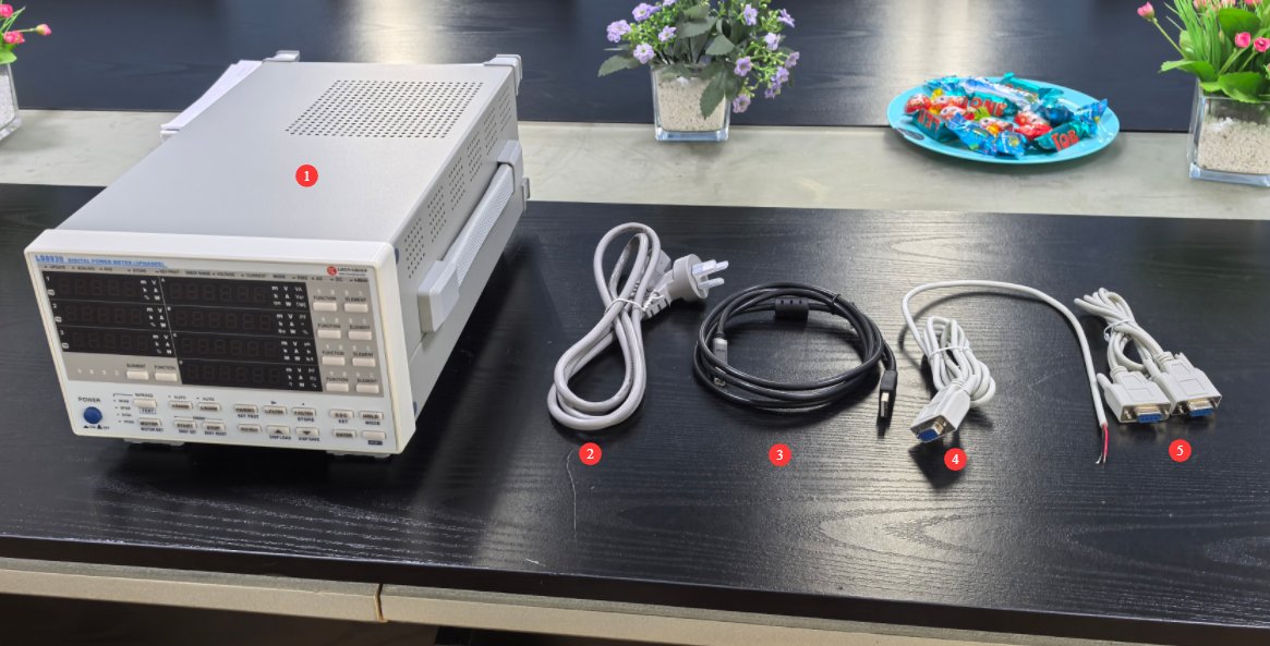
1.2.2 Unit Utama dan Aksesoris
| Jumlah | Note |
| ① | LS8930 Host |
| ② | Kabel Listrik |
| ③ | Kabel USB |
| ④ | RS-485 communication cable, spare |
| ⑤ | RS-232 communication cable, spare |
1.2.3 Mengunduh Dokumen Elektronik
Kami telah mengirimkan tautan unduhan untuk manual pengguna elektronik, perangkat lunak, kartu garansi, dan materi lainnya melalui email pada saat pengiriman. Silakan unduh sesegera mungkin. Jika Anda melewatkan email tersebut, jangan ragu untuk menghubungi kami untuk meminta tautan unduhan lagi.
2. Tindakan Pencegahan Keamanan
2.1 Keamanan Listrik
Before connecting the power cord, verify that the supply voltage is between AC 100 V and 240 V, with a frequency of 50 Hz or 60 Hz. You must use a three-prong outlet with a protective ground, and the protective ground resistance must be ≤4 Ω. Never cut or disconnect the protective ground wire, as doing so poses a risk of electric shock.
2.2 Keselamatan Lingkungan
Do not use in environments with flammable or explosive substances, strong electromagnetic interference, high temperatures and humidity, or excessive dust levels. Operating environment: Temperature 5°C to 35°C, relative humidity ≤ 65% RH.
2.3 Keselamatan Operasional
Before wiring, the power to both the meter and the device under test must be turned off; wiring while the circuit is energized is strictly prohibited. Connect voltage wires in parallel and current wires in series; under no circumstances should a current circuit be connected to a voltage terminal or a voltage circuit to a current terminal. After wiring, tighten the terminals and ensure that no bare wires are exposed to prevent short circuits or electric shock.
Do not apply voltages or currents that exceed the rated range.
3. Equipment Overview and Usage
3.1 Pengenalan Panel Belakang dan Pengkabelan
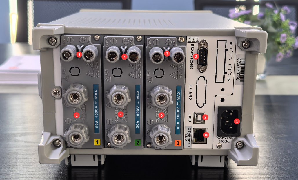
3.1.1 Pengenalan Panel Belakang
| Jumlah | Note |
| ① | Power Cord Jack |
| ② | Input Unit 1 Current Input Terminal |
| ③ | Input Unit 1 Voltage Input Terminal |
| ④ | Input Unit 2 Current Input Terminal |
| ⑤ | Voltage Input Terminal of Input Unit 2 |
| ⑥ | Input Unit 3 Current Input Terminal |
| ⑦ | Voltage Input Terminal of Input Unit 3 |
| ⑧ | RS232/RS485 interface, spare |
| ⑨ | Port USB |
| ⑩ | Ethernet port, spare |
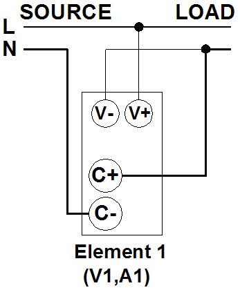
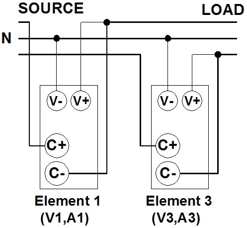
3.1.2 Input Module Wiring Diagram
Single-phase, two-wire (1P2W), connected to input unit 1:
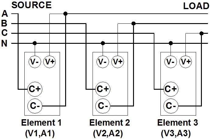
Three-phase, four-wire (3P4W), connected to input terminals 1, 2, and 3:
Three Voltages, Three Currents (3V3A):
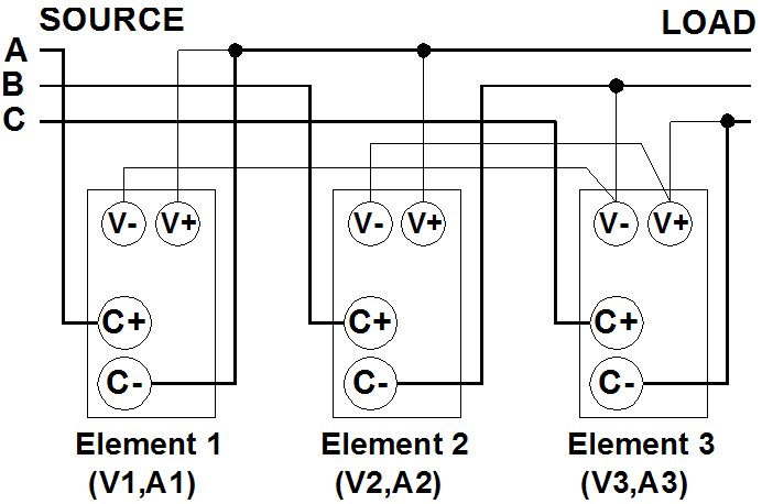
Three-phase, three-wire (3P3W), connected to input terminals 1 and 3:
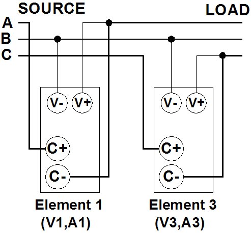
Single-phase, three-wire (1P3W), connected to input terminals 1 and 3:
3.2 Pengantar Panel Depan
| Jumlah | Note |
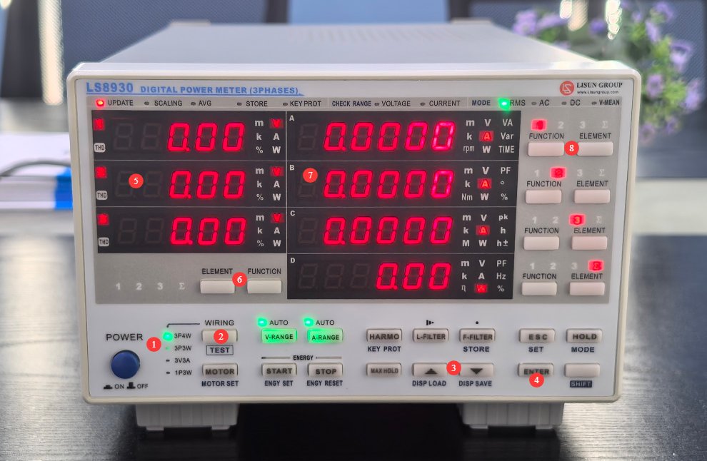
| ① | The wiring configuration display shows the default three-phase, four-wire system. This must match the actual wiring configuration on the back panel. Press the ② wiring button, then use ③ to select the correct wiring configuration, and finally press the ④ confirm button to confirm. |
| ⑤ | The three windows on the left display three-phase voltage by default; you can switch to display other parameters using the “Unit” and “Function” buttons at position ⑥. |
| ⑦ | By default, the four windows on the right display the three-phase current and total power. You can switch to display other parameters using the unit and function keys located to the right of each window, as shown at ⑧. |
4. Menggunakan Perangkat Lunak
4.1 Persiapan
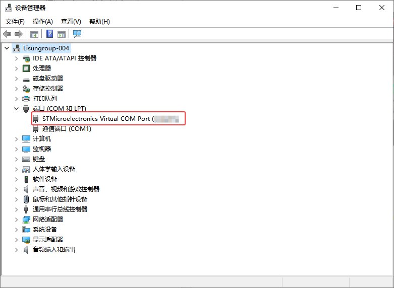
Connect the device to the computer using a USB cable. Open Device Manager on your computer; if you see the following ports listed, communication is working properly.
4.2 Ikhtisar Perangkat Lunak
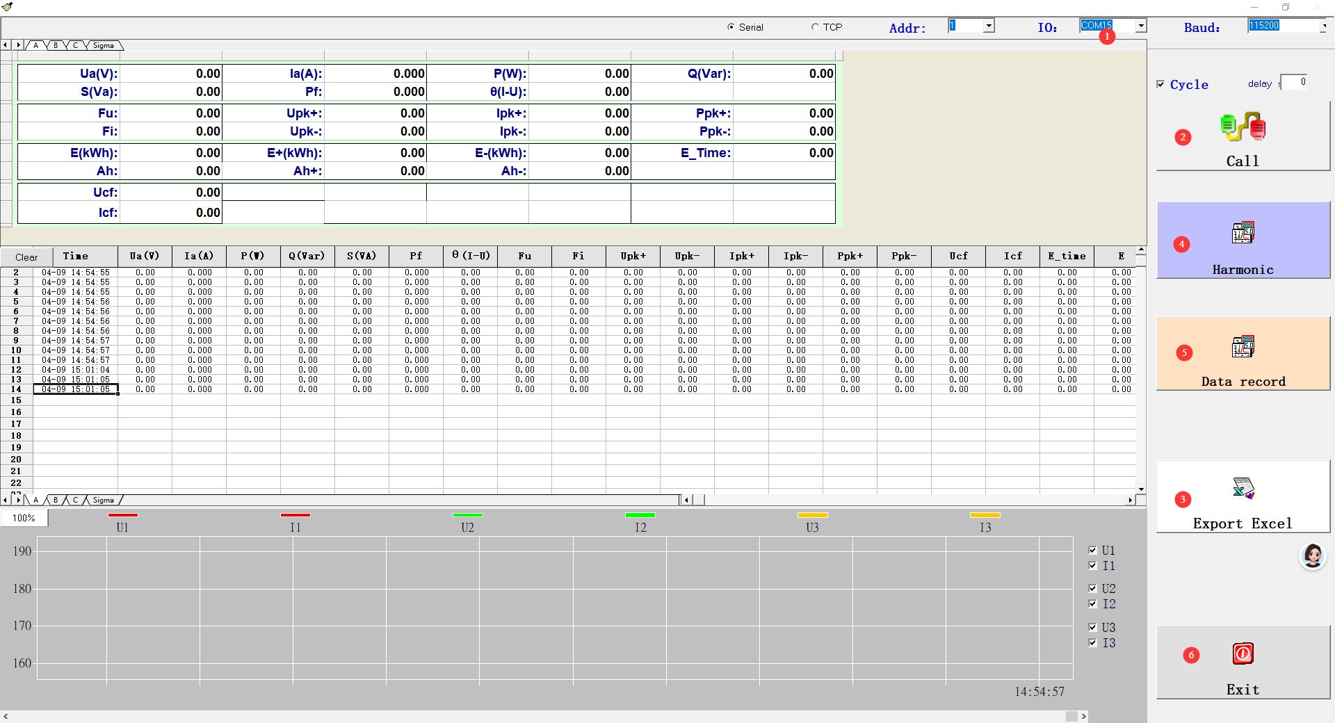
4.2.1 Software Startup Screen
| Jumlah | Note |
| ① | Select the correct port number based on the ports displayed in Device Manager. |
| ② | Tap to start recording data, then tap again to stop recording. |
| ③ | You can export all data from the current record to an Excel spreadsheet. |
| ④ | Harmonic Features |
| ⑤ | Data Calculation Features |
| ⑥ | Keluar dari Perangkat Lunak |
4.2.2 Harmonic Function Interface
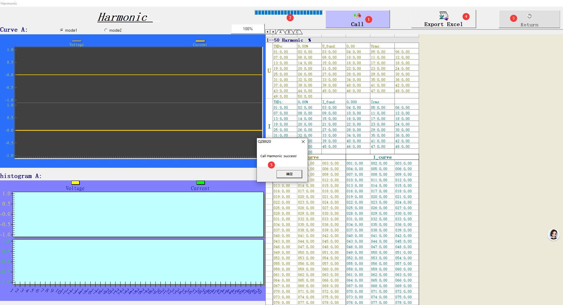
| Jumlah | Note |
| ① | Click to Read Harmonic Data |
| ② | Kemajuan Bar |
| ③ | Message: Read successful |
| ④ | You can export the current harmonic data to an Excel spreadsheet. |
| ⑤ | Kembali ke Layar Beranda |
4.2.3 Data Calculation Interface
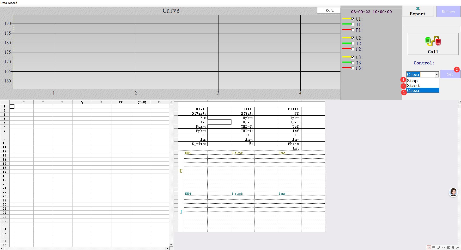
| Jumlah | Note |
| ① | Select “Clear,” press the Settings button, and past data will be automatically cleared. |
| ② | Tombol pengaturan |
| ③ | After clearing is successful, the mode automatically switches to Start; tap the Settings button again to automatically switch to Stop. |
| ④ | The device begins recording data |
| ⑤ | To stop, tap “Settings” again. The device will record and calculate the relevant data for this period. |
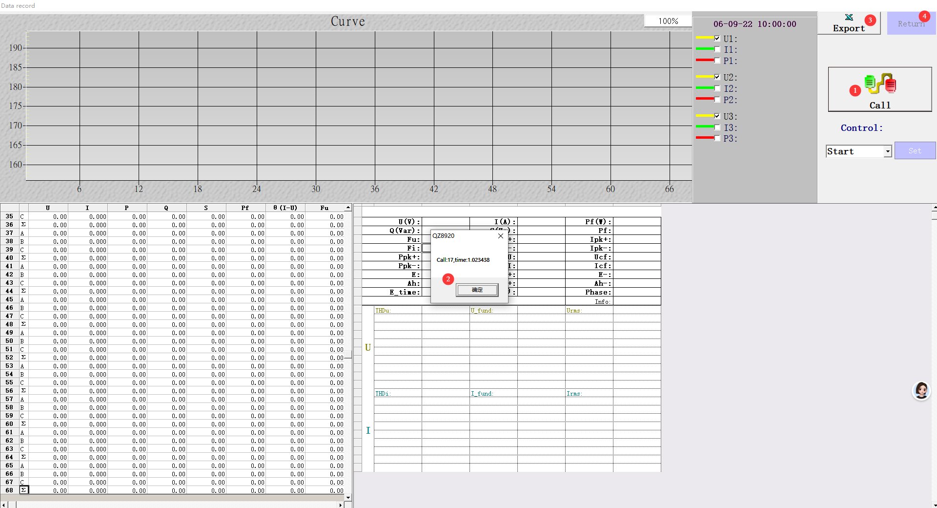
| Jumlah | Note |
| ① | Click to retrieve the relevant data into the software |
| ② | Retrieval successful |
| ③ | You can export the current data to an Excel spreadsheet. |
| ④ | Kembali ke Layar Beranda |
5. Pemeliharaan dan Perawatan Peralatan Harian
5.1 Perawatan Rutin
5.1.1 Pembersihan Harian
Be sure to turn off the power and unplug the power cord before cleaning. We recommend wiping the unit with a soft, antistatic cotton cloth and a mild detergent; do not spray liquids directly onto the unit. Do not use chemical solvents such as benzene, toluene, or acetone.
5.1.2 Pemeriksaan Rutin
Before each use, check that the power cord and terminal connections are secure and free of burn marks; ensure that the ventilation openings are not blocked; and after turning on the unit, verify that the indicator lights and display are functioning properly.
5.2 Spesifikasi Penyimpanan
For long-term storage, keep the product in a dry, dust-free, well-ventilated, and non-corrosive environment at a temperature of 5°C to 35°C and a relative humidity of ≤65% RH.
Matikan daya dan cabut semua kabel; bersihkan peralatan dan bungkus dengan plastik anti debu; hidupkan daya selama 10 menit setiap bulan untuk mencegah kerusakan akibat kelembapan pada komponen.
6. Pemecahan Masalah dan Penyelesaian Masalah Umum
| Gejala Kesalahan | Kemungkinan penyebab | Prosedur |
| Large Deviation in Measurement Values | Wiring error; the actual wiring configuration does not match the wiring configuration selected on the device’s front panel | Be sure to refer to Section 3.1.2 for the wiring scheme; be sure to refer to Section 3.2 when selecting the front panel wiring scheme. |
| Button not working | Keyboard is locked | Press SHIFT+HARMO (i.e., KEY PROT) to unlock the keyboard |
7. Daftar Kemasan
| Nomor | Nama | Jumlah |
| ① | LS8930 Host | Unit 1 |
| ② | Kabel Listrik | Sepotong 1 |
| ③ | Kabel USB | Sepotong 1 |
| ④ | RS-485 Communication Cable | Sepotong 1 |
| ⑤ | RS-232 Communication Cable | Sepotong 1 |
Appendix A: Indicator Lights and Label Descriptions
Unit Indicator Light Descriptions
The m (mill), k (kilo), and M (giga) indicators are order-of-magnitude indicators: 1M = 1000k, 1k = 1000, 1m = 0.001
| Lampu indikator | Parameter Teknis | Satuan |
| V | Tegangan | volt |
| A | terbaru | Amper |
| W | Kekuatan aktif | Ubin |
| VA | Kekuatan Semu | volt-ampere |
| adalah | Daya reaktif | Lelah |
| Hz | Frekuensi | Hertz |
| PF | Faktor kekuatan | |
| WAKTU | Waktu | Hour: Minute: Second |
| pk | Can be combined to form a peak | Determined by the group |
| h/h+ | Can be combined to form kilowatt-hours | Waktu |
| % | Relative Harmonic Content | |
| o | Perbedaan fase | Derajat |
| 1 | Satuan 1 | |
| 2 | Satuan 2 | |
| 3 | Satuan 3 | |
| Σ | Unit Terpadu |
Lampu Indikator Status
| Lampu indikator | Note | Catatan |
| UPDATE | Operating Status Indicator Light | A steady light indicates normal operation; a flashing light indicates that data is being updated. |
| PENJUAL | Storage Operation Indicator Light | A steady light indicates that the device is saving data; a flashing light indicates that data has been saved once. |
| SKALA | Magnification On Indicator Light | When the light is on, it indicates that the magnification is enabled; use the magnification data for calculations. |
| RMS | Mode Indicator Light | A lit indicator indicates that the calculated data is the effective value of the signal. |
| AC | Mode Indicator Light | When the light is on, it indicates that the calculated data represents the AC component of the signal. |
| DC | Mode Indicator Light | A lit indicator shows that the calculated data is the simple average of the signals. |
| V-MEAN | Mode Indicator Light | The voltage calculation data indicated by the lit light represents the rectified average value calibrated to the effective value. |
| KEYPROT | Perlindungan Tombol | A lit indicator means the button is locked and will not respond. |
| AVG | Average Data Indicator | A lit indicator means that the calculated value is the average of multiple data points. |
| TEGANGAN | Voltage Range Indicator Light | |
| ARUS | Current Range Indicator Light | |
| AUTO | Voltage or Current Auto-Range Indicator Light | When the light is on, it indicates that the voltage or current is within the range and is being automatically detected. |
| 3P4W | Wire-type indicator light | The indicator light shows that the meter is a three-phase, four-wire system. |
| 3V3A | Wire-type indicator light | The “Light On” Indicator Instrument Uses the 3-Voltage, 3-Current Meter Method |
| 3P3W | Wire-type indicator light | The indicator light shows that the meter is a three-phase, three-wire system. |
| 1P3W | Wire-type indicator light | The indicator light shows that the meter is single-phase, 3-wire. |
Button Indicator Light
| Lampu indikator | Note | Catatan |
| MAXHOLD | Maximum Value Indicator | When the light is on, it indicates that some of the calculated data values are at their maximum. |
| TAHAN | Data Retensi | A lit light indicates that the calculated data is held, meaning the data is no longer being updated. |
| MULAI | Points Accumulation Start Indicator Light | When the light comes on, it indicates that the accumulation of points has begun. |
| BERHENTI | Point Accumulation Stop Indicator Light | When the light comes on, it indicates that integration has stopped. |
| L-FILTER | Line Filter Indicator Light | A lit light indicates that the filter is on. |
| F-FILTER | Frequency Filter Indicator Light | A lit light indicates that the filter is on. |
| HARMO | Harmonic Display On Indicator Light | The light is on, indicating that the harmonic display is on. |
| SHIFT | Second Function Indicator Light | The light is on, indicating that the second function is active. |