
 Inggris
 中文简体
中文简体 Русский
 Español
 Português
 Türkçe
 العربية
 Deutsch
 Polski
 Italiano
 Français
 한국어
한국어 ไทย
ไทย Tiếng Việt
 日本語
日本語





























Tester Baterai
Pengguna manual
berlaku LISUN Model: LS5560,LS5562,LS5562A
1. Pemahaman Dasar tentang Peralatan
1.1 Gambaran Umum Peralatan
1.1.1 Klasifikasi Model
| Specifications/Model Number | LS5560 | LS5562 | LS5562A |
| Parameter Uji | RV/R/V (R: AC resistance; V: DC voltage) | ||
| Metode Pengujian | AC 4-Terminal Measurement (1 kHz) | ||
| Tegangan Input Maksimum | Rated input voltage: 60 VDC; maximum rated voltage to ground: 60 VDC | Rated input voltage: 300 VDC; maximum rated voltage to ground: 300 VDC | |
| Rentang Pengukuran Resistensi | Gigi 5 | Gigi 7 | |
| 3 mΩ to 30 Ω | 3 mΩ to 3000 Ω | ||
| Rentang Pengukuran Tegangan | DC 6V/DC 60V, two-setting switch | DC 6V/DC 60V/DC 300V, three-setting switch | |
1.2.1 Aplikasi Khas
It can simultaneously measure a battery’s AC internal resistance and DC voltage, making it suitable for applications such as factory-level testing, incoming inspection, after-sales repair, and assembly line sorting. It supports a wide range of standard individual cells, including lithium-ion, nickel-metal hydride, nickel-cadmium, coin-cell, and small power batteries.
1.2 Verifikasi Konfigurasi Peralatan
1.2.1 Membongkar
Saat membuka kemasan perangkat, tangani dengan hati-hati untuk menghindari goresan pada casing luar dengan alat tajam. Setelah membuka kemasan, periksa terlebih dahulu bagian luar perangkat untuk memastikan tidak ada deformasi atau penyok yang terlihat jelas, dan tombol-tombolnya tidak rusak atau longgar. Jika Anda melihat kelainan pada perangkat atau aksesorinya, jangan menyalakannya. Segera hubungi kami.
1.2.2 Unit Utama dan Aksesoris
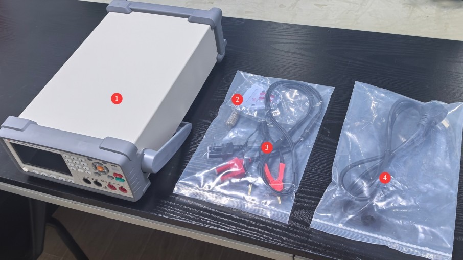
Lihat Gambar 1-1.
| Jumlah | Note |
| ① | LS556X Series Battery Tester |
| ② | HANDLER Interface Adapter, spare part, for connecting to your automated equipment |
| ③ | Test leads, one set each of red and black |
| ④ | Kabel Listrik |
Gambar-1 1
1.2.3 Mengunduh Dokumen Elektronik
We have already sent the download links for the digital user manual, warranty card, and other documents via email at the time of shipment. Please download them as soon as possible. If you missed the email, please feel free to contact us to request the download links again.
2. Tindakan Pencegahan Keamanan
2.1 Keamanan Listrik
Before connecting the power cord, verify that the supply voltage is between AC 110 V and 220 V, with a frequency of 50 Hz or 60 Hz. You must use a three-prong outlet with a protective ground, and the protective ground resistance must be ≤4 Ω. Never cut or disconnect the protective ground wire, as doing so poses a risk of electric shock.
2.2 Keselamatan Lingkungan
Do not use in environments with flammable or explosive substances, strong electromagnetic interference, high temperatures and humidity, excessive dust levels, or frequent vibrations. Ensure the following conditions for accuracy testing: 23±5°C, humidity ≤65% RH (non-condensing).
2.3 Prosedur Operasional
Do not operate the equipment or touch the test terminals with wet hands to prevent electric shock; do not measure batteries or circuits that exceed the equipment’s measurement range, and do not directly test the total voltage of a battery pack; do not modify, disassemble, or attempt to repair the equipment yourself to prevent fires and electric shock; the test lead terminals have sharp edges—do not touch the metal ends with bare hands to prevent cuts.
2.4 Lainnya
For any matters not covered in this manual, please proceed with caution or contact us.
3. Pengoperasian Peralatan
3.1 Pengantar Panel Depan
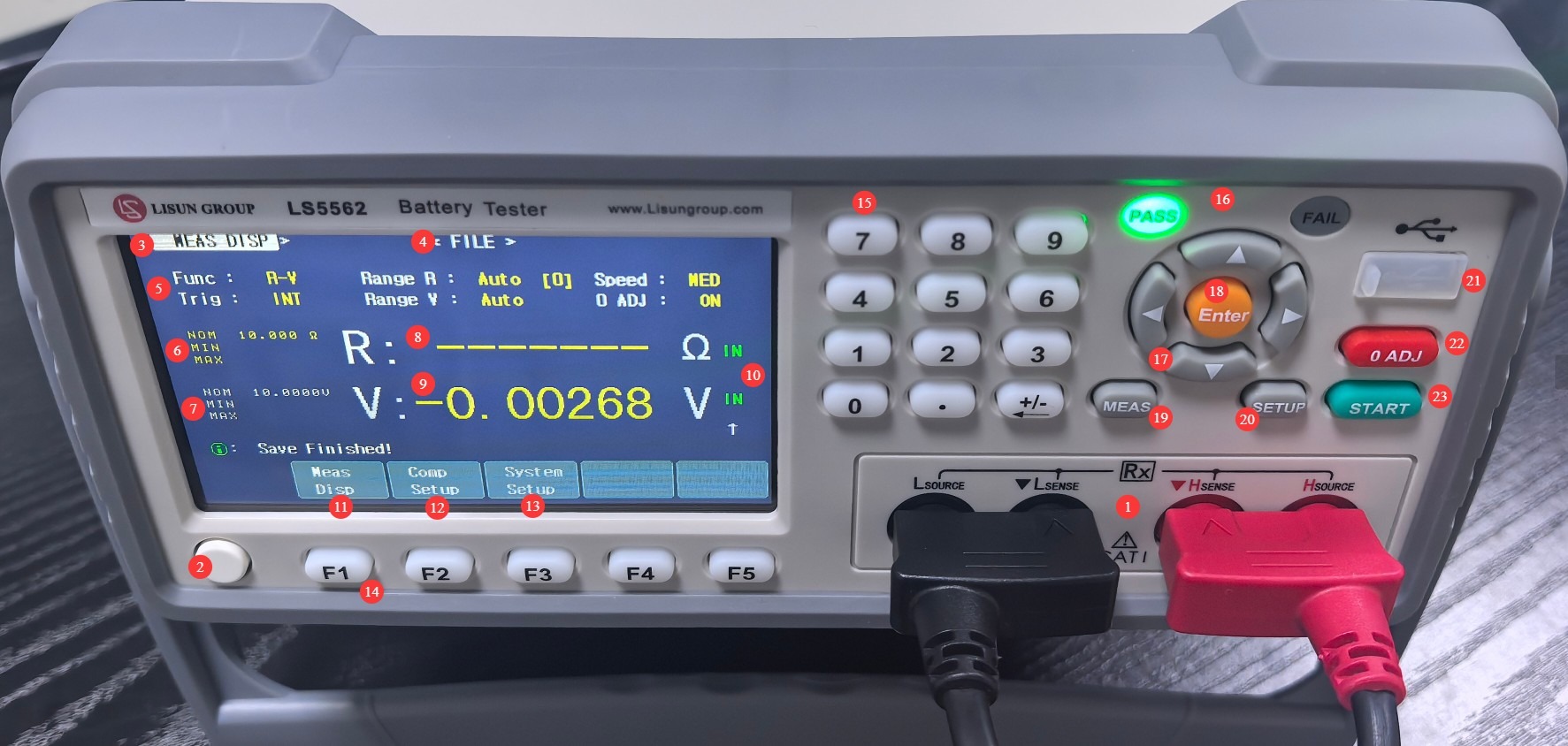
Lihat Gambar 3-1.
| Jumlah | Note |
| ① | Connect the red and black test leads. Align the triangle symbol on the test lead connector with the triangle symbol on the front panel test terminal, then insert the connector. |
| ② | Tombol power |
| ③ | Measurement Screen, Default Screen Upon Startup |
| ④ | File interface: Save test result files or manage historical test result files |
| ⑤ | Test Parameters Settings: Test Functions, Resistance Range, Test Speed, Trigger, Voltage Range, Zeroing (Recommended to Enable) |
| ⑥ | Setting the NOM (Nominal) Value, MIN (Minimum) Value, and MAX (Maximum) Value for Resistance |
| ⑦ | Setting the NOM (Nominal) Value, MIN (Minimum) Value, and MAX (Maximum) Value for Voltage |
| ⑧ | Measured Value of Resistor R |
| ⑨ | Actual Value of V (Voltage) |
| ⑩ | HI indicates above the upper limit, LO indicates below the lower limit, and IN indicates within the upper and lower limits. |
| ⑪ | Measurement Screen, Default Screen Upon Startup |
| 1 | Press F2 to access the comparison settings screen. |
| ⑬ | Press F3 to access the system settings interface. |
| ⑭ | F1–F5 Soft Keys |
| 3 | Tombol Angka |
| 5 | Indicator lights: PASS (green light for passing), FAIL (red light for failing) |
| ⑰ | Arrow keys: Move the cursor |
| ⑱ | Tombol konfirmasi |
| ⑲ | Measurement button: If you are on another screen, pressing the Measurement button will take you directly to the measurement screen. |
| ⑳ | Settings button: If you are on another screen, pressing the Settings button will take you directly to the comparison settings screen. |
| ㉑ | USB port: Allows you to export test result files to a USB flash drive or connect a USB flash drive to update the software. |
| ㉒ | Tombol Hapus |
| ㉓ | Trigger button: We recommend using an internal trigger, in which case this button does not need to be operated. |
Gambar-3 1
3.2 Pengenalan Panel Belakang dan Pengkabelan
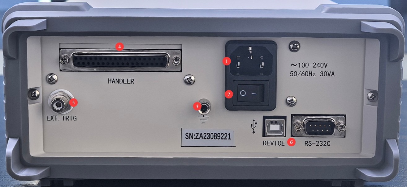
Lihat Gambar 3-2.
| Jumlah | Note |
| ① | Plug the power cord into the input power supply to connect the device to a suitable power source. |
| ② | Sakelar Daya Utama |
| ③ | Protective grounding terminal: Internally short-circuited to the grounding terminal on the power cord. If the power cord already provides adequate protective grounding, this terminal does not need to be connected. |
| ④ | HANDLER Interface: Reserved for connecting to your automation equipment |
| ⑤ | External Trigger Interface, for backup use; can be connected to your external trigger device |
| ⑥ | USB dan RS232 ports (for backup); if custom software is available, the device can be connected to a computer and controlled via the software. |
Gambar-3 2
4. Battery Testing Procedure
4.1 Powering On and Initializing the Equipment
Connect the input power supply cord → Flip the main power switch on the rear panel to the “I” (On) position → Press the power button on the front panel to turn on the unit → The screen will light up and begin the startup initialization process → Wait 3–5 seconds; the unit will automatically enter the measurement display screen (use the measurement button to switch screens quickly) → Connect the test leads.
4.2 Basic Parameter Settings
4.2.1 Selection of Test Functions
Move the cursor to “Function”: F1 (R: Measure resistance only), F2 (V: Measure voltage only), F3 (R+V: Simultaneous measurement). We recommend using F3 (R+V: Simultaneous measurement).
4.2.2 Range Setting
Move the cursor to “Resistance Range / Voltage Range,” F1 (Auto Range), F2 (Lock Manual Range), F3/F4 (Increase/Decrease Range). We recommend using F1 (Auto Range).
4.2.3 Test Speed Settings
Move the cursor to “Speed”: F1 (Very Fast), F2 (Fast), F3 (Medium), F4 (Slow). We recommend using F3 (Medium).
4.2.4 Trigger Source Settings
Move the cursor to “Trigger,” F1 (Internal Trigger: Automatic Continuous Test), F2 (External Trigger: Foot Switch / Button Trigger). We recommend using F1 (Internal Trigger: Automatic Continuous Test).
4.3 Zeroing Procedure
4.3.1 Scenarios Where Zeroing Is Applicable
When using the device for the first time, replacing the test leads, or when there are changes in ambient temperature or humidity; when test values are abnormal or a residual reading appears.
4.3.2 Zeroing Procedure
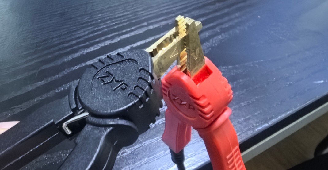
Clamp the red and black test leads together in a crisscross pattern, with the sides marked with a “V” facing the same direction, as shown in Figure 4-1.
Gambar-4 1
Press the 0 ADJ (Reset) button on the front panel to complete the reset.
4.4 Test Test Parameters Configuration
4.4.1 Single-Grade Sorting Settings
Move the cursor to the NOM (nominal value), MIN (minimum value), or MAX (maximum value) for internal resistance or voltage; enter a value using the numeric keys and press ENTER to confirm; the device automatically compares the value, and a green “PASS” light illuminates if the test is passed, or a red “FAIL” light illuminates if it is failed.
4.4.2 Multi-Tier Sorting Settings
Go to the comparison settings page, select the sorting level (Level 2 / Level 3), and set the upper and lower limits for each level.
4.5 Startup Testing and Data Reading
4.5.1 Battery Connection
Attach the red test clip to the battery’s positive terminal and the black clip to the negative terminal, ensuring they are securely fastened with no play; do not attach them to the battery’s screw terminals or to rusted or oxidized areas, and ensure good contact.
4.5.2 Uji Startup
Internal trigger: Measurement begins automatically after connecting the battery; read the value once it has stabilized. External trigger: Press the START button or press the foot switch to trigger a single measurement.
4.5.3 Reading Data
The screen displays real-time values for R (internal resistance) and V (voltage); if the reading is out of range, “——-” appears, indicating that you must switch to a higher range; PASS = Pass, FAIL = Fail.
4.6 Data Storage and Retrieval
Save: On the measurement page, move the cursor to “File” → F1 File Management → F2 Save, enter a filename, and confirm; Load: Select a file from the file list → F1 Load to retrieve historical parameters; Copy: F4 Copy to a USB drive to export data to a computer.
4.7 Ending the Test and Shutting Down
Remove the battery under test → Press the power button on the front panel to turn off the unit → Set the main power switch on the rear panel to “O” → Remove the test leads.
5. Pemeliharaan dan Perawatan Peralatan Harian
5.1 Pembersihan Harian
5.1.1 Cleaning the Panel and Housing
After unplugging the device, use a dry, soft cloth to wipe the casing, screen, and buttons to remove dust. Do not press hard on the screen, and do not use highly corrosive liquids such as acetone or thinners. The screen may be gently wiped with anhydrous ethanol.
5.1.2 Cleaning Test Terminals and Clamps
Use a cotton swab dipped in anhydrous ethanol to wipe the test terminals and the metal surfaces of the test clamps to remove oxidation and oil residue; clean once a month to ensure good contact.
5.2 Daily Reset
Whenever the test leads are replaced or the environment changes, perform a zeroing procedure as described in Section 4.3.
5.3 Spesifikasi Penyimpanan
5.3.1 Persyaratan Lingkungan Penyimpanan
Suhu: 5°C hingga 35°C; kelembapan relatif: ≤65% RH; lingkungan kering, bebas debu, dan bebas dari gas korosif.
5.3.2 Operasi Penyimpanan Jangka Panjang
Matikan daya dan cabut semua kabel; bersihkan peralatan dan bungkus dengan plastik anti debu; hidupkan daya selama 10 menit setiap bulan untuk mencegah kerusakan akibat kelembapan pada komponen.
5.4 Persyaratan Interval Kalibrasi
Untuk memastikan akurasi pengukuran dan keandalan operasional peralatan, disarankan agar peralatan tersebut secara berkala dikirim ke organisasi metrologi pihak ketiga yang berkualifikasi untuk kalibrasi. Interval kalibrasi yang disarankan adalah 12 bulan. Pengguna dapat menentukan interval kalibrasi spesifik berdasarkan frekuensi penggunaan, kondisi lingkungan, dan persyaratan sistem mutu.
6. Pemecahan Masalah dan Penyelesaian Masalah Umum
| Gejala Kesalahan | Kemungkinan penyebab | Prosedur |
| Tidak dapat menyala | The power switch on the rear panel is not turned on | Verify that the input power supply is functioning properly, then turn on the switch at the power input connector on the rear panel. |
| Hasil tes abnormal | The reset operation was not performed | Refer to Section 4.3 to correctly perform the reset operation. |
| Unable to trigger the test | Incorrect trigger source settings | As noted in Section 4.2.4, when the trigger mode is set to “External Trigger,” the trigger must be activated either by pressing the foot switch or the trigger button. |
| The data shown has not changed. | Trigger mode errors, system freezes | Switch the trigger source; restart the device |