
 Inggris
 中文简体
中文简体 Русский
 Español
 Português
 Türkçe
 العربية
 Deutsch
 Polski
 Italiano
 Français
 한국어
한국어 ไทย
ไทย Tiếng Việt
 日本語
日本語





























Pengukur Daya Digital
Pengguna manual
berlaku LISUN Model: LS2012,LS2050B,LS2050C.LS2050C-IEC
IS-MT Series Constant Temperature Integrating Sphere Operating Instructions
1. Pemahaman Dasar tentang Peralatan
1.1 Spesifikasi Teknis Utama
| Parameter Teknis | Note |
| Pelapisan Interior | The primary raw material is BaSO₄ (barium sulfate), which meets the requirements of standards such as CIE Pub. No. 84 (1989) and IES-LM-79. |
| Spectral Reflectance | 450 nm–800 nm: ρ(λ) ≥ 0.96; 380 nm–450 nm: ρ(λ) ≥ 0.92 |
| Rentang Kontrol Suhu | Temperature range: 25°C–55°C (reference ambient temperature: 25°C) |
| Ukuran | IS-1.5MT (Φ1.5 m), IS-1.75MT (Φ1.75 m), IS-2.0MT (Φ2.0 m). Note: Larger sizes are available upon request. |
1.2 Verifikasi Konfigurasi Peralatan
1.2.1 Membongkar
When unpacking the device, handle it gently to avoid scratching the outer casing with sharp tools. After unpacking, first inspect the exterior of the device to ensure that the sphere is closed and that there are no visible deformations or dents. If you notice any abnormalities with the device or its accessories, please contact us immediately.
1.2.2 Unit Utama dan Aksesoris
Main Unit: 1 IS-MT Series Constant Temperature Integrating Sphere.
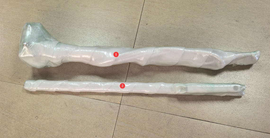
Accessories, see Figure 1.
| Jumlah | Note |
| ① | Base, including an E27 lamp holder |
| ② | Strip Light Fixture |
1.2.3 Mengunduh Dokumen Elektronik
We have already sent the download links for Instructions, warranty card, and other documents via email at the time of shipment. Please download them as soon as possible. If you have not received the email, please contact us to request the download links again.
2. Tindakan Pencegahan untuk Penggunaan
2.1 Keamanan Listrik
Before connecting the power cord, verify that the supply voltage is AC 220 V ±10% and the frequency is 50 Hz or 60 Hz. The equipment must be grounded for protection, with a grounding resistance of ≤4 Ω. Under no circumstances should the protective grounding wire be removed or disconnected, as doing so poses a risk of electric shock.
2.2 Key Contraindications Before the Procedure
2.2.1 Contraindications for Coating Protection
Do not allow any materials—including bare hands, cloths, or paper towels—to come into contact with the inner wall coating; do not allow liquids, oil, or dust to enter the ball;
Once the coating is extensively contaminated, it is virtually impossible to restore; do not attempt to wipe or polish it yourself.
2.2.2 Prohibited Operations by Personnel
Clean white cotton gloves must be worn when working inside the sphere; do not bring dusty or greasy tools into the sphere; and under no circumstances should you forcefully manipulate the sphere’s opening and closing mechanism, connectors, or internal wiring.
2.3 Code of Conduct During Operations
2.3.1 Internal Operating Procedures
Handle samples with care when installing or removing them; do not touch the inner wall of the sphere. Samples must be securely fastened to prevent them from falling and damaging the coating. When connecting wires, touch only the insulation; do not pull on the wire core.
2.3.2 Test Environment Specifications
Gunakan dalam a dust-free, vibration-free environment; place on a sturdy, level surface to prevent movement or shaking;
Avoid direct sunlight; ambient temperature: 25±2°C, humidity ≤70% RH.
2.3.3 Ventilation Opening Management Standards
There are three vents inside the Integrating Sphere: a cold air inlet, a hot air inlet, and an exhaust vent. These must be kept clear; do not cover or block them;
Air conditioning vents must remain unobstructed; do not cover or block them.
3. Introduction to The Constant Temperature Integrating Sphere
3.1 Left-front view
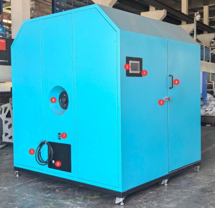
Lihat Gambar 2.
| Jumlah | Note |
| ① | Touchscreen for setting the temperature, starting tests, etc. |
| ② | Cross-shaped laser switch, used to activate the cross-shaped laser inside the Integrating Sphere to help position the light exactly at the center of the Integrating Sphere |
| ③ | Door latch |
| ④ | Door handle: After unlocking the latch, use the handle to open the right half of the Integrating Sphere. |
| ⑤ | Power cord, for connecting the Constant Temperature Integrating Sphere to a suitable power source |
| ⑥ | Saklar daya |
| ⑦ | Junction box: Connections for the Standard Light Source/sample fixture power cord (POWER) and sensing cable (SENSE) |
| ⑧ | Optical Fiber Interfaces for Constant-Temperature Bulb Temperature Sensors and Photometric Probes |
3.2 Rear-left View
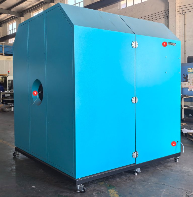
Lihat Gambar 3.
| Jumlah | Note |
| ① | Ventilasi AC |
| ② | Air Conditioner Drain Outlet |
| ③ | Connecting the Auxiliary Lamp Power Cord |
3.3 Inside The Constant Temperature Integrating Sphere
3.3.1 Left Hemisphere
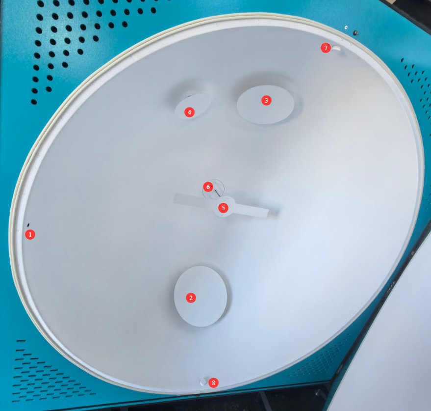
Lihat Gambar 4.
| Jumlah | Note |
| ① | Cross-Line Laser |
| ② | Hot Air Inlet |
| ③ | Cold Air Inlet |
| ④ | Ventilasi udara |
| ⑤ | Shield, used to prevent direct light from the light source from hitting the Optical Fiber and the photometric probe |
| ⑥ | Pemeriksaan Sensor Suhu |
| ⑦⑧ | Mounting holes for the test stage; the test stage can be mounted on the top or bottom of the Integrating Sphere to meet different testing requirements |
3.3.2 Right Hemisphere
See Figure 5, which shows the Auxiliary Lamp fixture used to mount the Auxiliary Lamp.
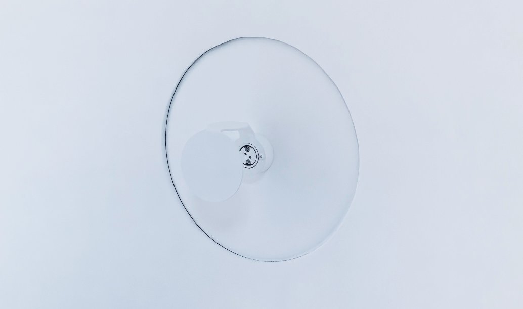
4. Assembly and Wiring of The Constant Temperature Integrating Sphere
4.1 Turning On The Constant Temperature Integrating Sphere
Refer to Section 3.1, connect the Constant Temperature Integrating Sphere to a suitable power source, and turn it on.
4.2 Mounting and Connecting the Stage
4.2.1 Persiapan
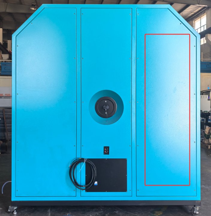
To facilitate transport, the stage and strip light fixture are secured inside the Integrating Sphere. Remove the panel marked in Figure 6 to reveal the stage and strip light fixture secured inside.
After installing the stage and connecting its cables as described in Section 4.2, and after aligning the crosshairs as described in Section 4.4.1, reinstall this panel.
4.2.2 Mount Installation
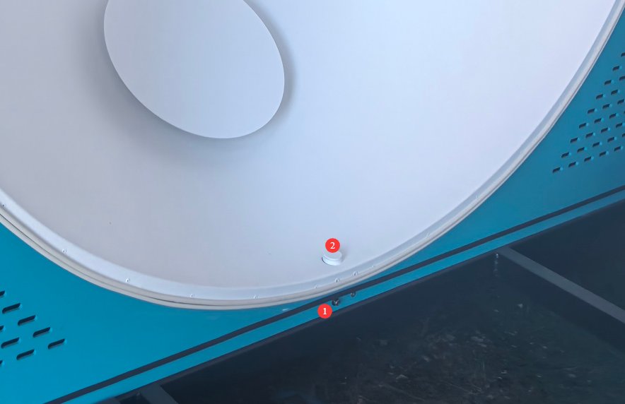
The stage can be mounted either on top of the Integrating Sphere or at the bottom. Here, we use the example of mounting the stage at the bottom, as shown in Figure 7.
| Jumlah | Note |
| ① | Loosen the mounting screws |
| ② | Then remove the spacer, and you can install the stage. |
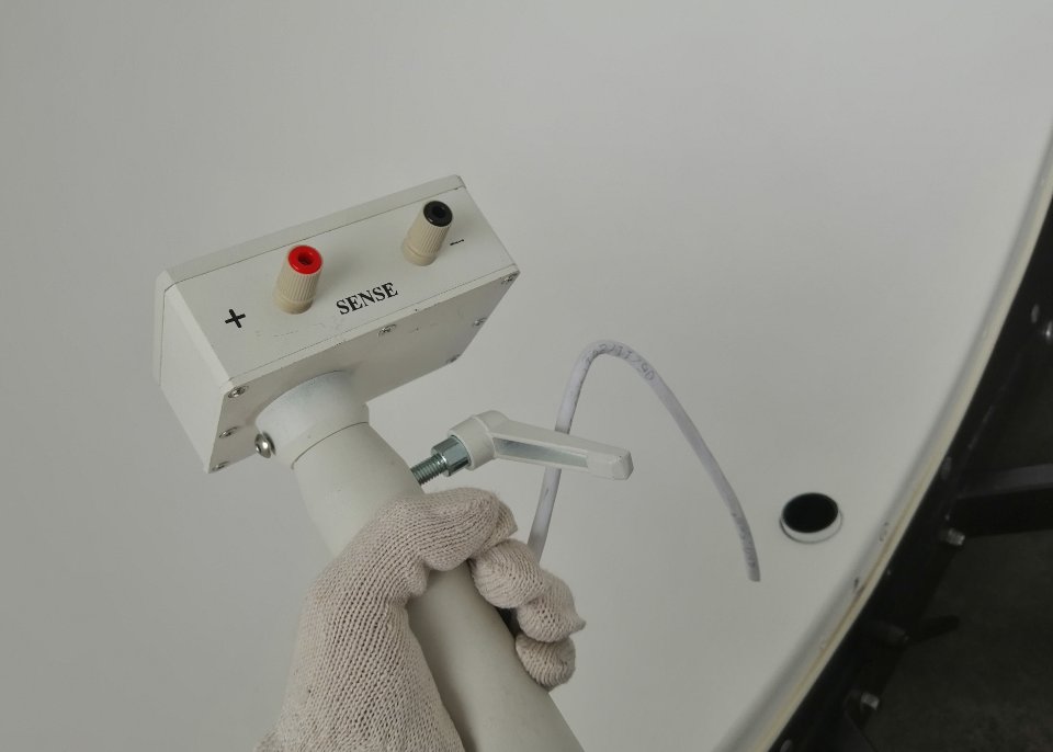
Feed the four-core cable for the stage through the bottom cable opening, as shown in Figure 8.
Then tighten the mounting screws to secure the stage.
4.2.3 Four-Conductor Cable Connection to the Stage
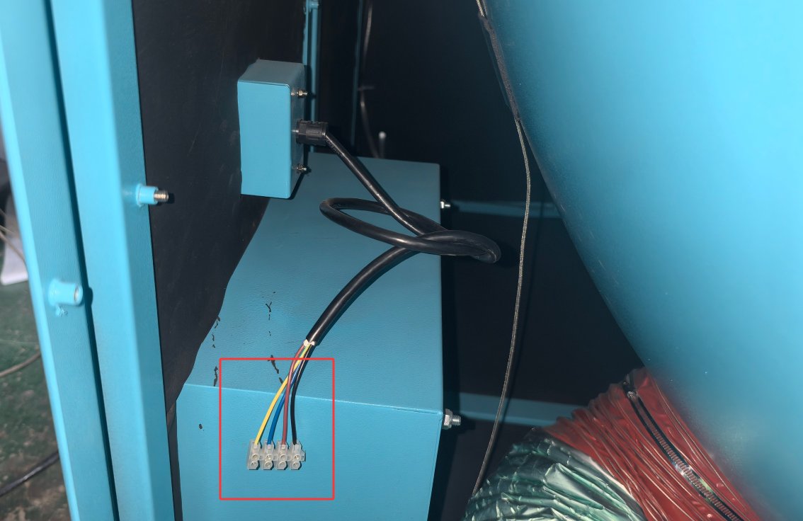
As shown in Figure 9, simply connect the four-conductor cable from the stage to the four-conductor wires provided inside the junction box, matching them one-to-one by color.
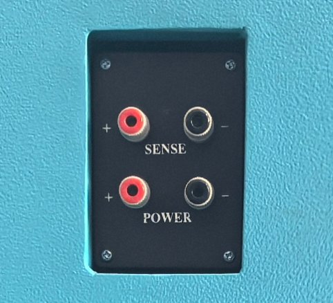
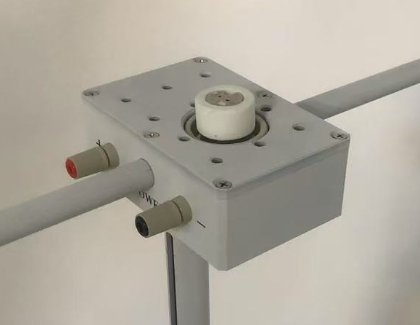
Both the junction box (Fig. 10) and the stage (Fig. 11) are equipped with red and black POWER and SENSE terminals. The terminals on both ends correspond one-to-one; simply connect them according to the cable colors.
4.3 Installation of Linear Light Fixtures
When you need to test linear lights, such as LED tubes, you can use a linear light fixture to secure the tube, as shown in Figure 12.
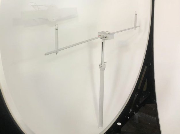
Note: When the strip light fixture is not in use, remove it and store it properly.
4.4 Cross-Line Laser
4.4.1 Crosshair Laser Calibration
Refer to Section 3.1 to turn on the cross-hair laser.
The direction of the cross-laser beam may shift or become misaligned during shipping. Please use a tape measure to confirm the center position of the Integrating Sphere, and then follow the instructions in Figure 13.
| petunjuk | Note |
| ① | Loosen the screws securing the cross-shaped laser. |
| ② | You can then adjust the direction of the crosshair laser. Once the direction is set, you can secure the screw back in place. |
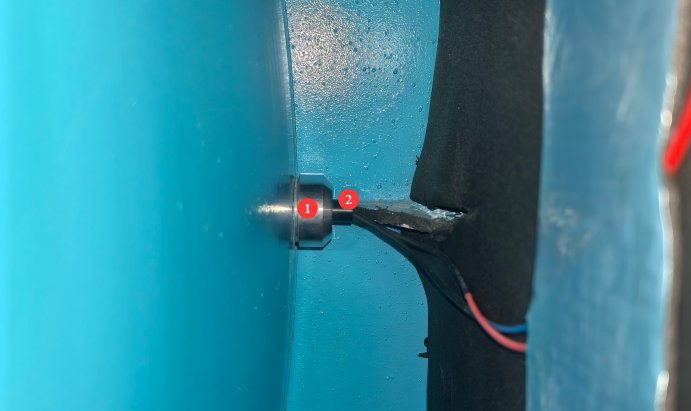
Once the crosshair laser is properly adjusted, you can reinstall the panel you removed.
4.4.2 Uses of Cross-Line Lasers
The crosshair laser is used to assist with light installation. Turn on the crosshair laser during installation to ensure that the light-emitting surface of the installed light is positioned exactly at the center of the Integrating Sphere. Turn off the crosshair laser during testing.
5. Hardware Operation of The Constant Temperature Integrating Sphere
5.1 Connecting Spectrometer Accessories
Refer to Section 3.1 to connect the spectrometer’s accessories—such as Optical Fibers, photometric probes, and temperature probes—to the corresponding dedicated ports on the Integrating Sphere.
5.2 Installation and Connection of Sample Luminaires
5.2.1 Bulb Lamps and Strip Lights
For incandescent bulbs, the mount includes an E27 socket. Incandescent bulbs can be installed directly into the E27 socket or connected to it using an adapter; no additional wiring is required inside the Integrating Sphere.
For strip lights, refer to Section 4.3 and use strip light fixtures.
5.2.2 Other Lighting Fixtures
For other types of lights, simply place them on the mounting platform and secure them using the M6 screw holes provided on the platform to prevent them from slipping off.
5.2.3 Confirmation of the Light-Emitting Surface Installation Location
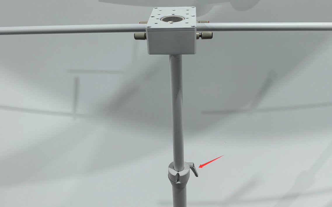
The stage is height-adjustable. Please refer to Section 4.4.2 and use the cross-hair laser to verify that the sample’s emitting surface is positioned exactly at the center of the Integrating Sphere. After adjusting the height, make sure the screws are securely tightened to prevent the stage from suddenly falling; see Figure 14.
5.2.4 Connecting the Sample Power Cord
Simply connect the sample power cord to the two terminals labeled “POWER” on the stage. The two red terminals and two black terminals labeled “POWER” and “SENSE” on the stage are already internally short-circuited, so there is no need to connect the wires to the “SENSE” terminals on the stage separately.
5.3 Connecting the External Power Cable and Sampling Cable
The four terminals on the front of the Constant Temperature Integrating Sphere’s junction box are used to connect to your other devices. The two “POWER” terminals connect to the sample power supply, and the two “SENSE” terminals connect to the voltage sensing leads.
5.4 Using the Auxiliary Lamp Fixture
Please install the Auxiliary Lamp into the MR16 lamp holder on the fixture, as shown in Figure 15.
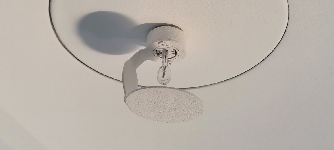
The Auxiliary Lamp clamp comes with two pre-installed power cords. When using the Auxiliary Lamp, connect it using an extension cord to a power source that meets the specified requirements.
6. Touchscreen Operation of The Constant Temperature Integrating Sphere
6.1 Introduction to the Program Interface
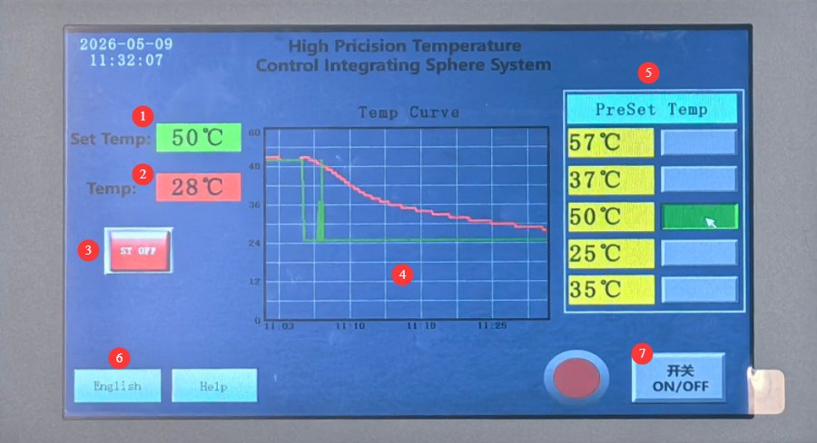
Lihat Gambar 16.
| Jumlah | Note |
| ① | Current Temperature Setting |
| ② | The current actual temperature inside the Constant Temperature Integrating Sphere |
| ③ | Self-adjusting switch: If you typically conduct tests using only one specific test temperature, you can turn this switch on to improve temperature control accuracy. Note: Turning this switch on or off has only a minor effect on temperature control. |
| ④ | The temperature curve shows time on the horizontal axis and temperature on the vertical axis; the red line represents the actual temperature, and the green line represents the set temperature. |
| ⑤ | Temperature Settings: The left column lists commonly used preset temperature points; press the selection button on the right to enable the corresponding temperature. You can also manually adjust the preset temperature values on the left. |
| ⑥ | Beralih antara Bahasa Mandarin dan Bahasa Inggris |
| ⑦ | Power button. Green indicates that the temperature control function is on, which brings the temperature inside the Integrating Sphere to the set temperature and maintains a constant temperature; red indicates that the temperature control function is off. |
6.2 Heating and Cooling Procedures
Constant Temperature Integrating Sphere is primarily used for high-temperature testing. It heats up relatively quickly, typically reaching the set temperature and stabilizing within about 10 to 20 minutes.
The entire interior of the device housing is lined with insulation to prevent heat loss from the interior of the Integrating Sphere. In other words, when the Integrating Sphere is at a high temperature, both chambers inside the device—the chamber containing the Integrating Sphere itself and the chamber between the Integrating Sphere and the outer housing of the device—are at a high temperature.
When you have just completed a high-temperature test and need to allow the internal temperature to cool down to room temperature (25°C), the cooling rate will be relatively slow if you rely solely on the equipment’s temperature control program. If necessary, you can open the Integrating Sphere directly to assist with cooling.
7. End-of-use procedure
7.1 Integrating Sphere Operation
You can allow the unit to cool down naturally using the temperature control program, or turn on the Integrating Sphere to accelerate heat dissipation. Once the temperature inside the sphere has returned to room temperature, if no further testing is required, you may turn off the device’s main power supply.
Once the temperature inside the Integrating Sphere has returned to room temperature, promptly remove the sample and wiring from inside the Integrating Sphere. Do not leave any unrelated accessories inside the Integrating Sphere.
7.2 Close The Integrating Sphere promptly
When the Integrating Sphere is not in use, be sure to keep it closed to prevent dust from entering.
8. Pemeliharaan dan Perawatan Peralatan Harian
8.1 Routine Internal Dust Cleaning
Frekuensi: Minimal seminggu sekali; Tools: Cold-air hair dryer (do not use hot air); Method: Gently blow away dust from inside the ball; do not allow any objects to come into contact with the coating.
8.2 Items to Be Inspected on a Regular Basis
8.2.1 Structural and Operation Checks
Each month, inspect the opening and closing handles and hinges; if any are loose, tighten the screws. Check that the gap where the two halves meet is even and that no light leaks through.
8.2.2 Inspection of the Inner Wall Coating
Inspect the interior coating monthly to ensure there is no peeling, yellowing, darkening, or staining.
8.3 Guidelines for Long-Term Storage
Storage conditions: Dry, protected from light, dust-free, temperature 0–40°C, relative humidity ≤70% RH; ensure the sphere is completely closed and covered with a dust cover; perform a thorough cleaning and inspection before storage.
8.4 Persyaratan Interval Kalibrasi
To ensure the measurement accuracy and operational reliability of the equipment, it is recommended that it be sent periodically to a qualified third-party metrology laboratory for calibration. The recommended calibration interval is 12 months. Users may determine the specific calibration interval based on usage frequency, environmental conditions, and quality system requirements.
9. Pertanyaan yang Sering Diajukan dan Solusinya
| Pertanyaan yang Sering Diajukan | Prosedur |
| Abnormal Heating and Cooling Function of the Integrating Sphere | There may be issues with the program’s backend parameters during transmission. Please contact us so we can check and adjust them. |
| Small areas of the coating on the inner wall of the Integrating Sphere have peeled off | If the sample luminaire is accidentally dropped, causing a small area of the coating on the interior wall of the Integrating Sphere to peel off, please contact us to obtain the necessary paint for repair. |
| Extensive peeling of the coating on the inner wall of the Integrating Sphere | If the inner coating has peeled off over a large area due to frequent bumps or drops of the fixture, and the coating cannot be repaired, please purchase a new Integrating Sphere. |
| The coating on the inner wall of the Integrating Sphere has darkened and yellowed over a large area. | If the device is left uncovered for an extended period, dust is not removed promptly, or it is used in harsh environments—such as those with excessive temperature or humidity, or direct sunlight—causing extensive yellowing of the inner wall coating that cannot be repaired, please purchase a new Integrating Sphere. |