
 Inggris
 中文简体
中文简体 Русский
 Español
 Português
 Türkçe
 العربية
 Deutsch
 Polski
 Italiano
 Français
 한국어
한국어 ไทย
ไทย Tiếng Việt
 日本語
日本語





























Penguji Tegangan Sisa
Pengguna manual
berlaku LISUN models: LS-RVT-2000W、LS-RVT-4000W、LS-RVT-5000W-3P
1. Membuka Kemasan dan Mengenal Perangkat Secara Dasar
1.1 Spesifikasi Teknis Utama
| Pilih Model | LS-RVT-2000W | LS-RVT-4000W | LS-RVT-5000W-3P |
| Maximum Output Power/Current | 2000 W / 10 A, single-phase | 4000 W / 16 A, single-phase | 5000 W / 7.5 A, three-phase |
| Rentang Tegangan Output | AC 0–242V | AC 0–380V | |
| Test Residual Voltage Range | 5–300.0 V; Resolution: 0.1 V; Accuracy: ±(1% of reading + 1 V) | ||
| Waktu Tes | 1–99 detik | ||
| Impedansi Uji | ≥100 MΩ (optional: >1000 MΩ) | ||
| Kapasitansi Masukan | 25 pF | ||
| Test Alarm Range | 5–300.0 V | ||
| Test Discrimination | Audible and visual alarms, and simultaneous disconnection of the output voltage | ||
| Antarmuka Komunikasi | RS-485 (opsional) | ||
1.2 Membuka Kemasan dan Memeriksa Isinya
1.2.1 Membuka Kemasan dan Pemeriksaan Visual
Saat membuka kemasan perangkat, tangani dengan hati-hati untuk menghindari goresan pada casing luar dengan alat tajam. Setelah membuka kemasan, periksa terlebih dahulu bagian luar perangkat untuk memastikan tidak ada deformasi atau penyok yang terlihat, dan tombol-tombolnya tidak rusak atau longgar. Jika Anda melihat kelainan pada perangkat atau aksesorinya, jangan menyalakannya. Segera hubungi kami.
1.2.2 Unit Utama dan Aksesoris
| Jumlah | Note |
| ① | LS-RVT Series Residual Voltage Tester Main Unit |
| ② | Kabel Listrik |
| ③ | Alligator clip wire, used to connect the host device to the metal casing of the test specimen |
Download links for the digital user manual, software, warranty card, and other materials have been sent via email. Please download them as soon as possible. If you missed the email, you can contact us to request the download links again.
1.3 Lingkup Penerapan Peralatan
This device is designed in accordance with GB/T 4706.1-2024 (Clause 22.5), GB 8898-2011 (Clause 9.1.6), GB 9706.1-2020 (Clause 8.4.3), GB/T 7000.1-2023 (Clause 8.2.7), and GB 4943.1-2022 (Clause 5.5.2.2). It is suitable for residual voltage testing of medical devices, household appliances, portable lighting fixtures, power connectors, and related equipment.
It can detect residual voltage between plug pins (live-neutral, live-ground, neutral-ground) and between the pins and the device housing, verifying whether the safety of capacitor discharge after the device is powered off meets standard requirements.
1.4 Key Design Considerations
By simulating the act of unplugging the device, it is disconnected from the power grid voltage at its peak (90/270 degrees). The test shows an impedance of ≥100 MΩ and an input capacitance of 25 pF, which meets the standard’s requirements for the input characteristics of measuring instruments, ensuring accurate and interference-free measurement results.
2. Tindakan Pencegahan Keamanan
2.1 Keamanan Listrik
Different equipment models have different input voltages, either AC 220V or AC 380V. Ensure that the input power supply matches the requirements on the equipment nameplate. Never connect the equipment to a voltage other than the rated voltage to prevent short circuits or equipment damage.
The equipment must be properly grounded. Before testing, check that the grounding terminal is securely connected. Do not start the test if the equipment is not grounded to prevent the risk of electric shock.
During operation, avoid contact with live parts such as the test specimen sockets and terminals. Wear insulated gloves during testing and keep your hands dry.
2.2 Prosedur Operasional
When adjusting the voltage control knob, turn it slowly clockwise; do not make rapid or drastic adjustments to avoid damaging the internal electronic components. After completing the test, be sure to first turn the voltage control knob counterclockwise to the minimum setting before turning off the power.
It is recommended to set the power-on duration to 1–3 seconds to prevent the equipment from overheating or the test specimen from being damaged due to prolonged power supply. The default number of test cycles is 10; this can be adjusted according to the standard, but should not exceed the maximum limit of 99.
When testing high-current (>10A) specimens, use the high-current terminals on the side of the equipment; do not connect through the 10A specimen socket to prevent the connector from overloading and burning out.
2.3 Environment and Protection
The equipment should be used in a dry, well-ventilated environment free of corrosive gases, with an ambient temperature of 0–40°C and relative humidity of ≤85%. Avoid moisture or excessive dust, which can cause equipment malfunctions.
Do not cover the ventilation openings while the equipment is running, and do not place flammable or explosive materials near the equipment. If an alarm sounds, stop the test immediately and restart the equipment only after troubleshooting the problem.
2.4 Lainnya
Untuk hal-hal yang tidak tercakup dalam panduan ini, harap berhati-hati atau hubungi kami.
3. Ikhtisar Peralatan
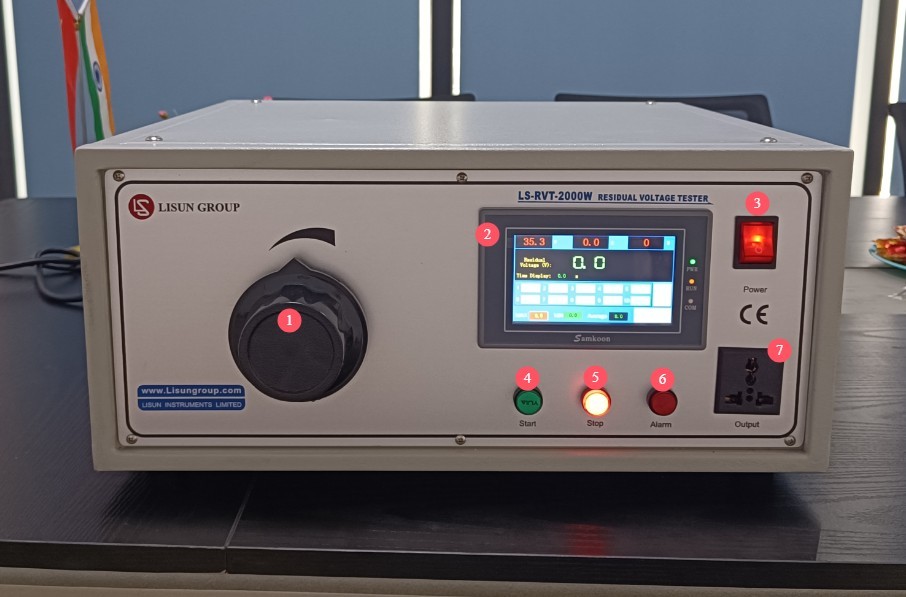
3.1 Bagian Depan Perangkat
| Jumlah | Note |
| ① Pressure adjustment knob | Clockwise to increase voltage, counterclockwise to decrease voltage; the adjustment range is 0–242 V AC for single-phase and 0–380 V AC for three-phase. The test voltage is used to power the test specimen. |
| ② Touchscreen | Displays test parameters and data results, and allows users to configure settings, etc. |
| ③ Power Switch | Controls the power on and off of the device; the touchscreen turns on automatically after startup. |
| ④ Start Button | Once the parameters have been set, press this button to start the test process, and the device will run according to the preset program. |
| ⑤ Stop Button | If an emergency stop occurs during testing or operation is terminated after testing is complete, pressing this button will cut off the device’s output voltage. |
| ⑥ Warning light | When the residual voltage exceeds the set alarm threshold, a red light illuminates, accompanied by an audible and visual alarm, and the power output is simultaneously cut off. |
| ⑦ Specimen Socket | Suitable for test specimens rated at ≤10A; connect the test specimen’s power plug; during testing, the unit outputs the set voltage and measures the residual voltage. |
Gambar 1
3.2 Side View of the Device
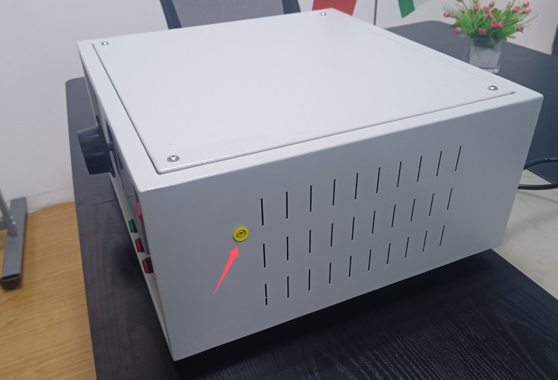
Chassis Connection Terminal: Connect a wire with an alligator clip to the metal chassis of the test specimen to measure the residual voltage between the pins and the chassis. If not required, keep the terminal clean and free of short circuits.
Gambar 2
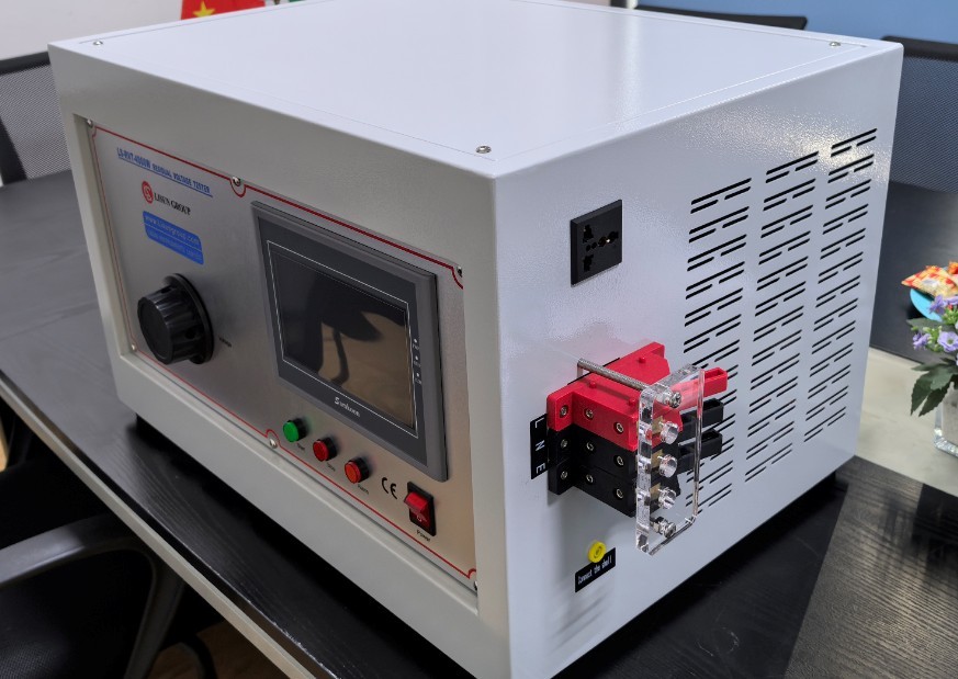
The LS-RVT-4000W high-power device also includes high-current terminals, which are suitable for high-power test specimens rated at >10 A and serve as a replacement for test specimen sockets.
Gambar 3
The LS-RVT-5000W-3P three-phase device is also equipped with terminal blocks as standard. This three-phase device can test both single-phase and three-phase specimens. When testing a single-phase specimen, simply connect one phase wire, the neutral wire, and the ground wire to the terminal blocks. Be sure to select the corresponding phase wire when setting the parameters.
3.3 Bagian Belakang Perangkat
Product nameplate and power cord.
Note: The LS-RVT-2000W standard unit comes with a standard plug-and-play power cord, while the LS-RVT-4000W high-power unit and the LS-RVT-5000W-3P three-phase unit come with fixed power cords featuring pre-wired terminals; please connect the power cord terminals to an appropriate power source.
4. Pengantar Program Layar Sentuh
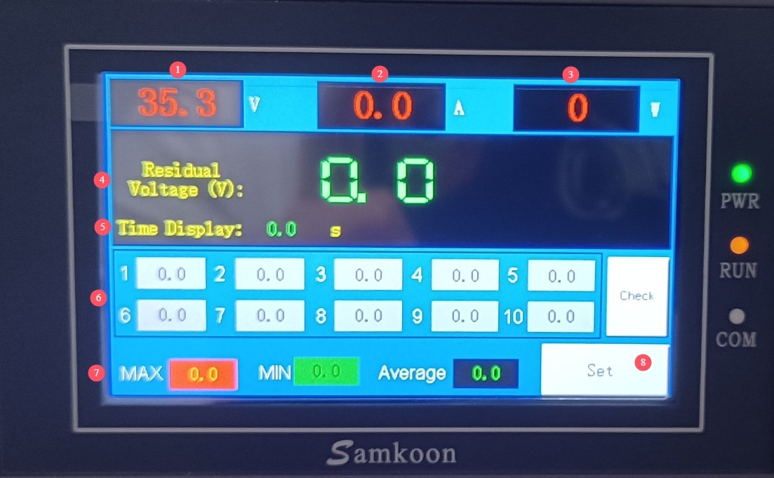
4.1 Monitoring Interface
| Jumlah | Note |
| ① Voltage Display | Indicates the Voltage Regulator’s output voltage (in V); when starting the test, power the test specimen at this voltage. |
| ② Current Display | Displays the real-time current (in A) flowing through the specimen during testing |
| ③ Power Display | Displays the real-time power consumption of the test specimen (in watts) |
| ④ Residual Voltage | Displays the remaining voltage measurement for the current test (in V) |
| ⑤ Timer Display | Alternately displays the power-on countdown and the power-off countdown (in seconds) |
| ⑥ List of Residual Voltage Test Values | Displays the remaining voltage data (in V) for cycles 1–10 of the test |
| ⑦ Arithmetic value of the residual voltage | Displays the maximum, minimum, and arithmetic mean of the test values (in volts), allowing for a quick determination of compliance. |
| ⑧ Settings Button | Click to open the settings screen |
Gambar 4
4.2 Antarmuka Pengaturan Parameter
| Jumlah | Note |
| ① The appliance is powered on | Set the power supply duration for the test specimen. The default is 3 seconds, but this can be adjusted according to the standard (for example, if GB 4706.1 requires a 1-second power interruption, set it to 1 second). |
| ② Cyclic Measurement | Set the number of consecutive tests; the default is 10. GB 8898 requires 10 repetitions to identify the worst-case scenario; it is recommended to keep the default setting. |
| ③ Time-Delay Measurement | Set the delay time before measurement begins after a power outage. The default is 1 second; this must be set according to the applicable standard (e.g., set to 2 seconds if GB 8898 requires 2 seconds, or to 5 seconds if GB/T 7000.1 requires 5 seconds). |
| ④ Power-off angle | The default setting is 90/270 degrees (voltage peak), which meets the “peak-off” requirement of the standard and requires no modification. |
| ⑤ Alarm Voltage | Set the upper limit for residual voltage according to standard specifications (e.g., ≤34 V for household appliances, ≤60 V for medical devices, ≤50 V for lighting fixtures, etc.) |
| ⑥ Selection of Measurement Items | Options include Live-Neutral (LN), Live-Earth (LE), Neutral-Earth (NE), Live-to-Shell (L Shell), and Neutral-to-Shell (N Shell). Select the appropriate option based on your testing needs. To measure voltage to ground, you must connect both the ground terminal and the test lead. To measure voltage to the shell, you must connect both the alligator clip and the test lead. |
| ⑦ Calibration Button | No action is required. If the device displays abnormal parameters, please contact us for calibration. |
| ⑧ Back Button | Save the settings and return to the monitoring screen |
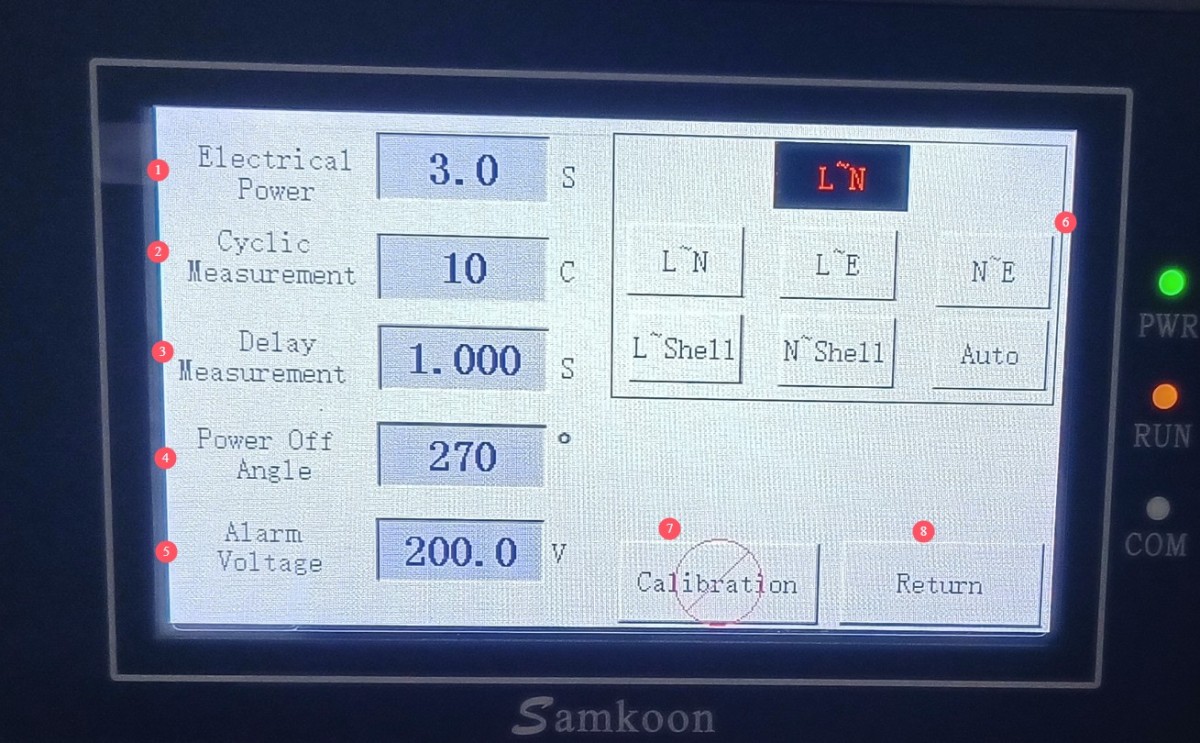
Gambar 5
5. Persiapan Sebelum Ujian
5.1 Persiapan Sampel
Check that the specimen is free of damage and that the power plug is intact; then insert the specimen’s power plug into the equipment’s specimen socket (≤10A) or connect it to the high-current terminal block (>10A);
To test the residual voltage between the test pin and the enclosure, connect one end of the alligator clip lead to the device’s ground terminal and clip the other end to the metal enclosure of the test specimen (ensuring good contact and no oxidation);
Set the test specimen’s switch to the “On” position. If the test specimen has multiple switches, set them to the most unfavorable positions (as required by the standard, the switches may affect the discharge results).
5.2 Parameter Presets
Configure the settings as described in Section 4.2.
6. Residual Voltage Test
6.1 Initiating the Test Process
On the monitoring screen, slowly turn the voltage adjustment knob clockwise to set the output voltage to the test specimen’s rated operating voltage (e.g., 220 V). Stop adjusting once the voltage reading has stabilized;
Press the “Start” button on the front of the device, and the device begins to operate according to the preset program: it supplies power to the test specimen for the “Appliance Power-On” duration; at this point, the current and power displays show normal values; Once the power supply time has elapsed, the device cuts off the power supply at the peak voltage and enters the power-off countdown; after the “Delayed Measurement” time has elapsed, it automatically measures the residual voltage of the selected parameter, and the results are saved to the test value list; After completing a single test, following a 10-second power-off interval, the device automatically repeats the above steps until the “Cycle Measurement” count is reached.
6.2 Memantau Proses Pengujian
During the test, monitor the status of the alarm indicator. If the remaining voltage exceeds the alarm threshold, the device will immediately trigger an audible and visual alarm and cut off the output. Press the stop button to clear the alarm, record the data that exceeded the threshold, and inspect the test specimen;
During the cycle test, the device automatically records data without requiring manual intervention.
6.3 Evaluation and Recording of Results
Once the test is complete, the device automatically stops outputting power. Check the “Remaining Voltage Arithmetic Values” (maximum, minimum, and average) on the monitoring interface;
Pass/Fail Criteria: If none of the test values exceed the set alarm voltage (and comply with the corresponding standard limits), the test specimen passes; if any value exceeds the limit, the test specimen fails;
Record all test data (values from 10 cycles, maximum, minimum, and average) and include information such as the test standard, specimen model, and test date; file the records for future reference.
6.4 Equipment Shutdown Procedure
After testing is complete, first slowly turn the voltage adjustment knob counterclockwise to set the output voltage to the minimum (0 V); press the stop button, and after confirming that the device has cut off the output, turn off the device’s power switch; remove the test specimen and its connecting cables; if alligator clip leads were used, put them away promptly.
7. Pemeliharaan dan Perawatan Peralatan Harian
7.1 Perawatan Rutin
Before turning on the equipment, check that the exterior is clean and free of damage, that the power cord and alligator clip wires show no signs of aging or breakage, and that all connectors are secure;
After the test is complete, wipe down the surface of the equipment and the test area of the specimen with a dry cloth;
Check the test specimen sockets and high-current terminals for oxidation or burnout; if any are found, wipe them with a specialized contact cleaner. If necessary, contact us to have the terminals replaced;
Check to see if the cooling fan inside the equipment is operating normally. If you hear any unusual noises or if it is not running, contact us immediately for repair.
7.2 Penyimpanan Jangka Panjang
If the device will not be used for an extended period, store it in a dry, well-ventilated environment, away from moisture and direct sunlight;
Lepaskan semua kabel, simpan aksesori secara terpisah, dan tutupi perangkat dengan kain anti debu;
Nyalakan perangkat selama 30 menit setiap bulan untuk mencegah kerusakan komponen elektronik internal.
Memecahkan Masalah dan Menyelesaikan Masalah Umum
| Gejala Kesalahan | Kemungkinan penyebab | Prosedur |
| No voltage output after starting the test | The voltage adjustment knob is not set to the rated voltage; the test specimen is not connected to the power supply. | Turn the voltage adjustment knob clockwise to the specified voltage; check that the test specimen switch is turned on and that the plug is securely connected. |
| The measured value is 0 or abnormally low | Incorrect selection of measurement items, poor grounding, or test specimens not functioning properly | Return to the parameter settings screen to verify the measurement items; check that the alligator clip leads are securely connected to the specimen housing; confirm that the specimen operates normally after power is applied. |
| Frequent alarms, readings exceed limits | Incorrect alarm voltage setting, malfunction of the specimen discharge device | Verify the standard limit values and reset the alarm voltage; check whether the internal discharge resistor in the test specimen is damaged, and retest after replacing the specimen. |
| Layar sentuh tidak responsif | Equipment Freezes, Touchscreen Malfunctions | Turn off the power, wait 30 seconds, and then turn it back on; if there is still no response, contact us to have the touchscreen repaired. |
| Abnormal Current/Power Display | Short circuit in the test specimen; poor contact at the terminals | Stop the test immediately and check whether the test specimen has a short circuit; reconnect the test specimen’s plug or terminals to ensure good contact. |