
 Inggris
 中文简体
中文简体 Русский
 Español
 Português
 Türkçe
 العربية
 Deutsch
 Polski
 Italiano
 Français
 한국어
한국어 ไทย
ไทย Tiếng Việt
 日本語
日本語





























Penguji Penguapan Air Akumulasi Embun Beku
Pengguna manual
berlaku LISUN Model: LS-B65
1. Pemahaman Dasar tentang Peralatan
1.1 Basis for Equipment R& D
This device strictly complies with GB/T 4706.13-2024, “Safety of Household and Similar Electrical Appliances—Part 13: Special Requirements for Refrigerating Appliances, Ice Cream Makers, and Ice Makers” (IEC 60335-2-24:2025), specifically Clause 11.102 and Appendix BB. It employs the controlled-heating-source evaporation method specified by the national standard, to simulate water vapor evaporation and cabinet frosting with minimal additional heat loss. It is used to verify that no abnormal temperature rise occurs during the operation of the refrigeration appliance’s defrosting system and to confirm that the thickness of the frost layer after frosting meets the standard requirements.
Maximum evaporation rate: 2 g/h (4 W rated power, at ambient temperature inside the unit); Standard water supply ratio: 2 g of water per liter of unit volume per week (mandatory standard requirement).
1.2 Operating Principle of the Equipment
A controlled heating source built into the equipment evaporates a measured volume of purified water at a constant temperature; the water vapor diffuses evenly throughout the interior of the refrigeration appliance, forming a standard layer of frost on the cold inner walls and the surface of the evaporator, thereby simulating the natural frosting conditions that occur during the appliance’s daily use.
After frost formation is complete, activate the defrosting system of the appliance under test. In conjunction with this device, continuously monitor environmental parameters and appliance temperature to determine whether any non-conformities—such as overheating or incomplete defrosting—occur during the defrosting process.
The equipment features an insulated block-style housing that prevents excess heat from the heating source from transferring to the refrigeration chamber, utilizing only directed thermal energy to evaporate moisture and thereby avoiding any additional thermal interference that could affect test results.
1.3 Scope of Application and Limitations of the Equipment
All types of refrigeration appliances—including household refrigerators, freezers, ice cream makers, and commercial ice makers—that fall within the scope of GB/T 4706.13-2024 (IEC 60335-2-24:2025).
Not intended for use in testing high-pressure, low-temperature specialty refrigeration equipment or large-scale industrial refrigeration units.
1.4 Equipment and Documentation Verification
1.4.1 Membongkar
When unpacking the device, handle it gently to avoid scratching the casing with sharp tools. After unpacking, first inspect the exterior of the device to ensure there is no visible deformation or dents, and that the knobs and switches are not damaged or loose. If you notice any abnormalities with the device or its accessories, do not turn it on. Please contact us immediately.
1.4.2 Mengunduh Dokumen Elektronik
Kami telah mengirimkan tautan unduhan untuk manual pengguna elektronik, sertifikat kalibrasi, kartu garansi, dan dokumen lainnya melalui email pada saat pengiriman. Silakan unduh sesegera mungkin. Jika Anda belum menerima email tersebut, silakan hubungi kami untuk meminta tautan unduhan lagi.
2. Tindakan Pencegahan Keamanan
2.1 Standar Keselamatan Listrik
Equipment Rated Power Supply: AC 220 V ±10%, 50/60 Hz.
Do not disassemble the heating element or wiring terminals while the device is powered on; be sure to turn off the device switch before plugging in or unplugging the power cord.
2.2 Safety During Experimental Procedures
Use only pure water at room temperature as the test medium; do not add salt, detergents, or chemical reagents. When filling the evaporating dish with water, ensure that no water spills out.
During the test, there is a significant temperature difference between the inside and outside of the chamber. Do not touch the cold inner walls of the refrigeration unit being tested with your bare hands to prevent frostbite.
Do not open or close the cabinet door during the test run; this ensures test accuracy and prevents cold air from blowing directly onto the body.
2.3 Prosedur Tanggap Darurat
If you notice any unusual noises, odors, smoke, or other abnormalities, immediately turn off the main power supply and troubleshoot the problem.
3. Ikhtisar Peralatan
3.1 Diagram Standar
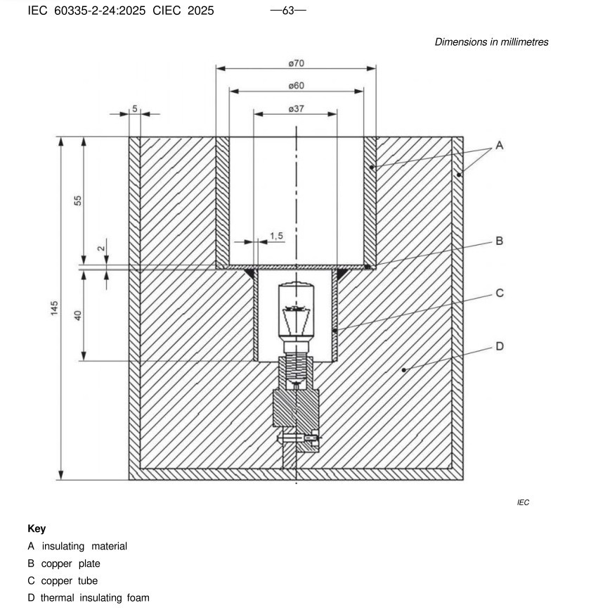
See Figure 3-1 (taken from the IEC standard) for a schematic diagram of a frost-condensing moisture evaporation device.
Gambar-3 1
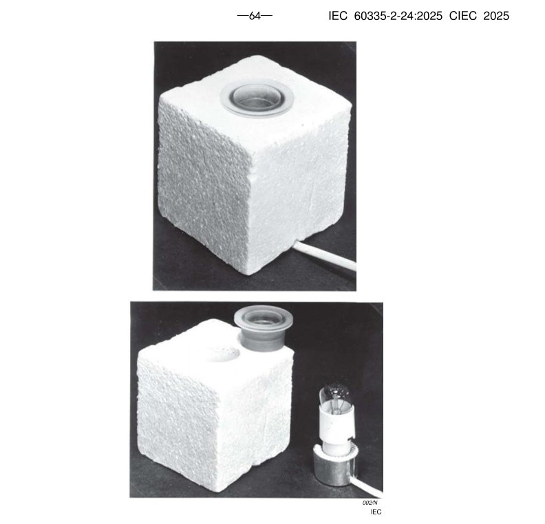
Water vapor evaporation and frost formation apparatus; see Figure 3-2 (taken from the IEC standard).
Gambar-3 2
3.2 Actual Photo
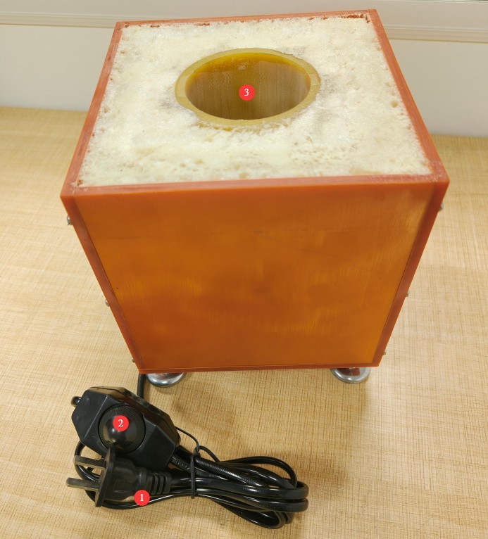
Lihat Gambar 3-3.
| Jumlah | Note |
| ① | Kabel Listrik |
| ② | Power Adjustment Knob: An external power meter is required for use; use the knob to adjust the power to 4W. |
| ③ | Evaporation Dish |
Gambar-3 3
4. Persiapan Sebelum Ujian
4.1 Persiapan Lingkungan Pengujian
4.1.1 Calibration of Environmental Parameters
Maintain the laboratory temperature at 23°C ± 2°C and the humidity at 30%–90% RH. Ensure that the test area is free from direct drafts and direct sunlight.
4.1.2 Site and Space Preparation
Leave at least 30 cm of clearance around the refrigeration unit being tested for heat dissipation. Ensure the area where the unit is placed is level, and that the floor is dry and free of standing water.
4.2 Preparation of the Refrigeration Unit Under Test
4.2.1 Pretreatment of Instruments
Remove any debris, residual frost, and standing water from inside the cabinet, and ensure that the interior walls are clean and free of grease;
Run the equipment under no-load conditions until the internal temperature stabilizes at the rated operating temperature.
4.2.2 Voltage Operating Conditions Settings
Adjust the supply voltage of the refrigeration unit under test to the most unfavorable voltage within the range of 0.94 to 1.06 times the rated voltage, and record the current supply voltage value.
4.2.3 Classification by Operating Conditions
Manual defrosting tool: Allow the system to operate normally until conditions for frost formation on the evaporator are met;
Automatic/Semi-automatic defrosting devices: Lock the defrost cycle to ensure that the frost layer does not exceed the normal thickness that would accumulate during two defrost cycles.
4.3 Preparation of Test Water and Consumables
4.3.1 Requirements for Test Water
Use only deionized or distilled water at room temperature; do not use tap water or bottled water to prevent impurities from affecting evaporation and frosting results.
4.3.2 Calculation of Water Consumption
Calculation formula: Total water consumption per test = Total tank volume (L) × 2 g/(L・week);
Example: 140-liter chamber, defrosted twice weekly; water consumption per frost formation test = 140 L × 2 g/L × 1/2 = 140 g (injected intermittently in multiple batches);
Weighing: Use the supplied high-precision electronic balance to accurately weigh the water, keeping the error within ±0.1 g.
4.4 Equipment Installation and Positioning
4.4.1 Positioning and Installation of the Enclosure
Open the door of the refrigeration unit under test, place the LS-B65 unit at the geometric center of the cabinet, and adjust the bottom supports to ensure the unit is level.
4.4.2 Pipe and Cable Layout
Extend the water-injection tube above the evaporating dish so that the tube opening is directly above the center of the dish, 5–10 mm above the liquid surface;
Route the equipment’s power cord and test leads through the gap in the cabinet door, then close the door to ensure a tight seal.
5. Water Vapor Evaporation and Frost Formation and Defrosting Tests
5.1 Konfirmasi Parameter Uji
Adjust the initial power of the heating source: Under low-temperature chamber conditions, set the initial power to 1 W, and after preheating for 3 minutes, gradually increase it to the standard power of 4 W;
Intermittent Water Injection: Determine the amount of water injected per cycle and the injection interval based on the duration of the test.
5.2 Frost
Verify that the refrigeration unit is operating normally and that the door is completely closed. The unit will continue to evaporate moisture until a uniform layer of frost forms on the evaporator surface. Ensure that the frost layer does not exceed the normal thickness that would accumulate within two automatic defrost cycles.
5.3 Defrost Performance Test Procedure
5.3.1 Start Defrosting
After the frost accumulation test is paused, activate the defrosting system of the test unit in accordance with national standards.
Stand-alone appliances: Supply power to the defrost system separately in accordance with the relevant provisions of the standard; integrated compressor appliances: Supply power to the entire unit at the specified voltage to initiate defrosting.
If the appliance has a built-in defrost timer, set it to the manufacturer’s recommended duration.
5.3.2 Monitoring the Defrosting Process
Turn on the external temperature logger to continuously monitor the temperatures at the appliance’s evaporator and key points inside the cabinet throughout the entire process;
Observe the melting of the frost layer, and record the start and end times of the defrosting process, as well as the drainage of meltwater;
Key Criteria: Throughout the entire defrosting process, the temperature of any part of the appliance must not exceed the specified limit.
5.3.3 Evaluation of Defrosting Results
Pass: All frost has been completely removed, with no ice residue remaining; there were no instances of overheating or water leakage or overflow throughout the entire process;
Failed: Incomplete defrosting, localized overheating, and accumulation and overflow of melted water; abnormal data was recorded.
5.4 Operating Multiple Consecutive Test Runs
5.4.1 Conclusion of Single-Group Testing
After completing a set of frost formation and defrosting tests, pause all procedures and remove any residual moisture from the evaporating dish.
5.4.2 Requirements for Periodic Rest
Allow at least 10 minutes between test runs so that the heat source and the chamber can cool down naturally, thereby preventing continuous high temperatures from accelerating component aging.
5.5 Recording and Archiving of Test Data
Data items to be recorded: cabinet volume, total water consumption, heating power, frost formation duration, defrost duration, temperatures at each monitoring point, appliance supply voltage, and frost layer status.
6. Pemeliharaan dan Perawatan Peralatan Harian
6.1 Daily Maintenance After Use
Wipe away any water residue from the inner walls and base of the evaporating dish using a lint-free, soft cloth. Do not use steel wool or corrosive cleaning agents. Ensure that the equipment is free of standing water and dust.
6.2 Pemeliharaan Selama Periode Tidak Aktif Jangka Panjang
After the equipment has been powered off and routine maintenance has been completed, place a desiccant in the evaporation dish, cover the entire unit with a dust cover, and store it in a dry, well-ventilated storage room; power it on for 30 minutes each month to prevent components from becoming damp and damaged.
6.3 Persyaratan Interval Kalibrasi
Untuk memastikan akurasi pengukuran dan keandalan operasional peralatan, disarankan agar peralatan tersebut secara berkala dikirim ke lembaga metrologi pihak ketiga yang berkualifikasi untuk kalibrasi. Interval kalibrasi yang disarankan adalah 12 bulan. Pengguna dapat menentukan interval kalibrasi spesifik berdasarkan frekuensi penggunaan, kondisi lingkungan, dan persyaratan sistem mutu.
7. Pemecahan Masalah dan Penyelesaian Masalah Umum
| Gejala Kesalahan | Kemungkinan penyebab | Prosedur |
| The equipment’s heating power is too low or unstable | Low power supply voltage to the equipment; unstable grid voltage fluctuations | Check the power supply line and distribution voltage, and adjust them to fall within the equipment’s rated range of AC 220 V ±10%; if voltage fluctuations are severe, connect an external voltage stabilizer before turning on the device. |