
 Inggris
 中文简体
中文简体 Русский
 Español
 Português
 Türkçe
 العربية
 Deutsch
 Polski
 Italiano
 Français
 한국어
한국어 ไทย
ไทย Tiếng Việt
 日本語
日本語





























Karakteristik Pemutus Sirkuit Sistem Uji Komprehensif
Pengguna manual
berlaku LISUN Model: LS-B60
1. Pemahaman Dasar tentang Peralatan
1.1 Ikhtisar Produk
The LS-B60 Circuit Breaker Tripping Characteristics Comprehensive Test System is a professional testing device developed by LISUN GROUP specifically for performance testing of miniature circuit breakers and molded-case circuit breakers. The system employs PLC-based intelligent integrated control and a touchscreen HMI for operation. It features an integrated design that combines the test chamber with the main unit, incorporating dedicated test stations. Through a scientifically designed wiring configuration, it meets the testing requirements for circuit breakers ranging from 1- to 4-pole specifications. The system features precise temperature control, ensuring that the testing process takes place in a stable and safe environment, making it the ideal equipment for circuit breaker manufacturers, testing institutions, and R& D departments to conduct quality control and performance verification.
1.2 Standar yang berlaku
| Nomor Standar | Judul Standar |
|---|---|
| GB 14048.1-2020 | Low-Voltage Switchgear and Control Gear—Part 1: General Requirements |
| GB 14048.2-2020 | Low-Voltage Switchgear and Control Gear—Part 2: Circuit Breakers |
| GB 10963.1-2020 | Overcurrent-Protection Circuit Breakers for Household and Similar Uses—Part 1: AC Circuit Breakers |
| GB 16917.1-2014 | Residual-current operated circuit breakers (RCBOs) with overcurrent protection for household and similar uses—Part 1: General rules |
| IEC 60947-1 | Peralatan sakelar dan kontrol tegangan rendah – Bagian 1: Aturan umum |
| IEC 60947-2 | Low-voltage switchgear and controlgear – Part 2: Circuit breakers |
| IEC 60898-1 | Molded-case circuit breakers for household and similar installations – Part 1: Circuit breakers for a.c. |
1.3 Major Test Items
| uji Produk | Note |
|---|---|
| Delayed Trip Characteristic Test | Verification of the agreed-upon non-trip and agreed-upon trip behavior at 1.13x, 1.45x, and 2.55x the rated current |
| Instantaneous Trip Characteristic Test | Verification of instantaneous short-circuit tripping for currents ranging from 3 to 10 times the rated current |
| Uji Kenaikan Suhu | Measure the temperature rise of each component of the circuit breaker under rated operating current |
1.4 Operating Principle of the Equipment
The equipment consists of a smart controller, an AC contactor, a current booster, a current stabilizer, a standard current transformer, a touchscreen, and a temperature control module.
The delay test utilizes a high-speed DSP data processor to achieve precise closed-loop current control via a software-based PID algorithm. The current value is set digitally via the touchscreen, and the output is automatically adjusted.
The transient test uses a gear-shifting method to output high currents, triggered by a foot switch, to rapidly capture the response time and current values.
The temperature rise test uses multiple thermocouples to measure the temperature at various points on the test specimen and, in conjunction with the chamber’s temperature control system, simulates the temperature rise process under stable ambient conditions.
2. Tindakan Pencegahan Keamanan
2.1 Persyaratan Kualifikasi Personel
This equipment is a large-scale, precision electrical testing device with a complex structure. It poses risks of arc burns and electric shock during high-current output; therefore, operators must undergo professional training and pass a qualification exam before operating the equipment independently.
Equipment maintenance and calibration must be performed by qualified technical personnel; non-professionals are strictly prohibited from disassembling or repairing the equipment while it is energized.
Operators should undergo regular safety training and be thoroughly familiar with all safety operating procedures and emergency response protocols.
2.2 Pedoman Keselamatan Operasional
When connecting test specimens, standard test leads with the appropriate wire gauge—based on the specimen’s rated current—must be selected, and the terminals must be securely fastened to prevent heat generation or arcing due to poor contact.
Before placing or removing the test specimen, ensure that the equipment is in the off state or that the specimen’s own switch is in the “off” position. Under no circumstances should the test specimen be plugged in or unplugged while energized, to prevent arcing or sparks from damaging the product or causing burns to personnel. When
conducting high-current tests, take precautions against arc burns; do not move or touch the test specimen until the test has stopped or the circuit breaker has fully tripped. A staff member must be present at all times during
equipment testing and operation. If the operator needs to leave temporarily or suspend the test, the equipment’s main power supply must be turned off. If any abnormalities occur during
testing—such as unusual odors, smoke, or strange noises—the main power supply must be immediately shut off; the equipment may only be used again after the fault has been resolved.
2.3 Persyaratan Keamanan Listrik
The equipment’s input power supply is AC 220 V ±10%, 50 Hz ±1 Hz. A dedicated circuit breaker must be used, installed in an easily accessible location and clearly labeled, so that power can be immediately shut off in an emergency. The cross-sectional area of the
input power supply cable must not be less than 2.5 mm²; a protective grounding wire that complies with relevant standards must be connected, and the grounding resistance must meet safety requirements.
The equipment contains high-current circuits; do not open the cabinet door or touch the internal terminals while the power is on. Although the
equipment is equipped with triple protection against short circuits, overloads, and ground faults, this does not exempt users from adhering to safe operating procedures.
2.4 Persyaratan Lingkungan Kerja
Ambient temperature: -5°C to +40°C.
Relative humidity: Maximum 80% at 20°C; decreases linearly to 50% at 30°C.
Altitude: The installation site must not exceed 2000 meters above sea level.
Installation Location: Keep the equipment away from heat sources, water sources, and direct sunlight; keep it away from sources of strong electromagnetic interference and severe vibration or shock; ensure good ventilation and an environment free of excessive dust and corrosive gases.
The distance between the back of the equipment and the wall must be at least 1 meter to ensure adequate heat dissipation and maintenance space.
3. Ikhtisar Peralatan
Lihat Gambar 3-1.
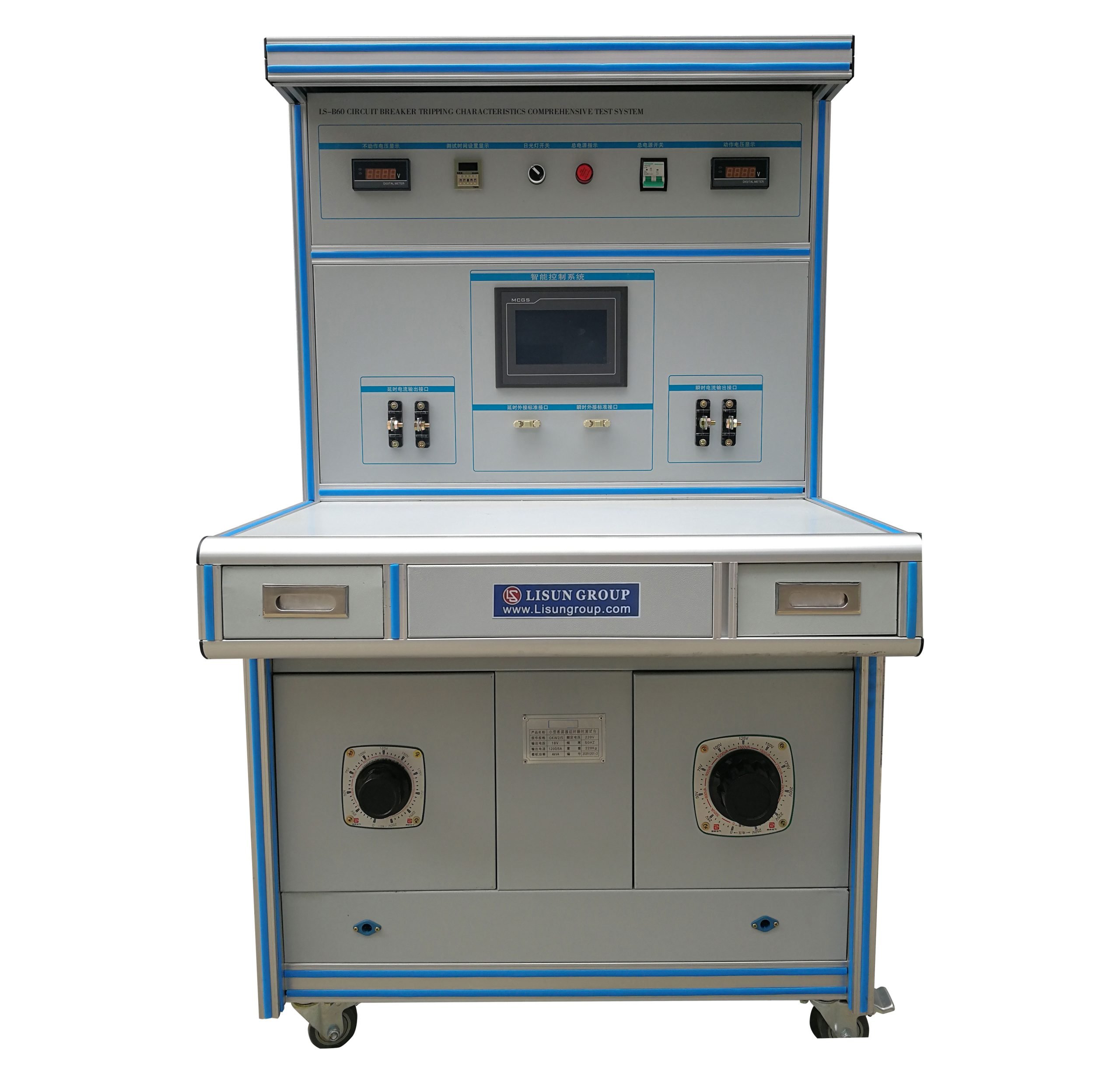
The equipment features a vertical cabinet-style design with an aluminum alloy frame. It is divided into three sections: the upper control area, the middle operating area, and the lower cabinet area. The base is equipped with swivel casters for easy mobility.
3.1 Upper Control Zone
Located on the top panel of the unit, these components integrate power control and status indicators: Digital voltmeter/ammeter: Displays the input power supply status in real time; Power switch and indicator light: Controls the unit’s main power supply; Emergency stop button: A red, round button that immediately cuts off the output when pressed in an emergency; Function switches and indicator lights: Indicate the status of different test circuits.
3.2 Central Control Area
The core operating area of the equipment includes: Touchscreen: Located in the center, it serves as the main human-machine interface for all parameter settings, test control, and data display; Terminal Block Area: Distributed on both sides of the touchscreen, arranged in a terminal block configuration, and divided into delayed-response and instantaneous-response test stations to accommodate the wiring requirements for 1–4-pole circuit breakers; Permukaan kerja: A horizontal work surface used to place test specimens and tools; drawers are provided beneath the surface for storing accessories.
3.3 Lower Cabinet Area
Equipment Power and Control Section: Current adjustment knobs: One on each side, corresponding to the coarse adjustment functions of different current circuits; Center Cabinet Door: Houses core electrical components such as the current booster, contactors, and PLC controller; Bukaan Ventilasi: Located at the bottom of the cabinet to ensure proper heat dissipation for internal components; Papan nama: Affixed to the center cabinet door, indicating the equipment model, rated parameters, and other information.
4. Pengantar Program Layar Sentuh
4.1 Introduction to the Main Interface
After the equipment is powered on, the touchscreen automatically displays the system’s main interface. The top of the screen shows the current date, time, system operating status, and day of the week; the middle section is the function selection area, which includes four main function entries: “Delay Test,” “Transient Test,” “Temperature Rise Test,” and “Parameter Settings”; the bottom displays auxiliary information such as the system’s operating duration.
4.2 Delay Test Interface
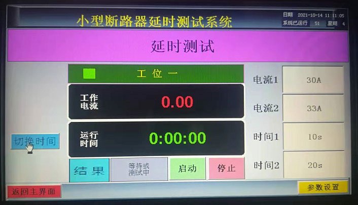
Click the “Delay Test” button on the main screen to enter the single-station delay test screen, as shown in Figure 4-1.
4.2.1 Interface Display and Parameter Descriptions
Operating Current Display Area: Displays the real-time effective value of the current output (unit: A);
Run Time Display Area: Displays the elapsed time of the current test in real time (format: hours: minutes: seconds);
Test Current 1 (Lower Limit Current): A predetermined current setting at which the circuit breaker will not trip, typically 1.13 times the rated current;
Test Current 2 (Upper Limit Current): The agreed-upon trip current setting, typically 1.45 or 2.55 times the rated current;
Test Time 1 (Lower Limit): The agreed-upon threshold for the hold time during which the device must not trip;
Test Time 2 (Maximum Time): The maximum action time threshold for a specified trip;
Status Indicator Area: Displays test statuses such as “Standby,” “Testing,” “Pass,” and “Fail”;
Tombol kontrol: “Start,” “Stop,” “View Results,” “Settings,” “Return to Main Screen”;
4.2.2 Parameter Settings Subscreen
Click the “Parameter Settings” button to access the calibration and mode settings screen:
Pemilihan Mode Operasi: Switch between Standard Mode and Custom Mode;
Pengaturan Jangkauan: The range ratio for each range can be configured;
Calibration Area: Click the “Calibration Enable” button; when the indicator light turns green, the device enters calibration mode. Based on the reading from the external reference meter, enter the actual current value in the “Reference Meter Input” field. Click “Calibration Output” to complete the current calibration for that range;
Start-up Voltage Setting: Adjusts the initial value of the current output to optimize the smoothness of the current rise;
4.3 Transient Test Interface
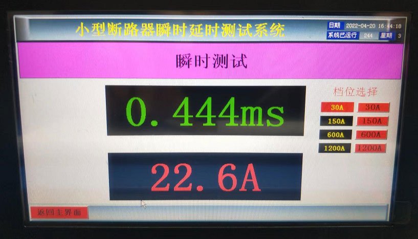
Click the “Instant Test” button on the main screen to enter the instant test screen, as shown in Figure 4-2.
4.3.1 Gear Selection and Display
Operating Current Display: Displays the real-time effective value of the instantaneous output current (unit: A);
Operating Time Display: Displays the circuit breaker’s trip time (in ms);
Current Setting Area: Offers a selection of fixed current settings (such as 30A, 150A, 600A, 1200A, etc.); simply click the corresponding button to select the desired setting;
Note: The set current value must not exceed the maximum output value for the selected setting;
4.3.2 Time Parameter Settings
Maximum Action Time: Set the maximum action time for a pass/fail determination (configurable from 1 to 200 ms);
Minimum Action Time: Set the minimum action time required for a pass determination (configurable from 1 to 200 ms);
After the test is complete, the system automatically compares the action time with the set threshold and displays a “Pass” or “Fail” result;
4.4 Temperature Rise Test Interface
Click the “Temperature Rise Test” button on the main screen to enter the temperature rise test control screen:
Chamber Temperature Setting Section: Set the target temperature for the internal environment of the test chamber (room temperature to 50°C);
Channel Temperature Display: Real-time temperature readings for 12 temperature channels;
Test Current Setting: Set the operating current value for the temperature rise test;
The temperature rise curve shows: You can view the temperature-over-time curves for each channel;
Test Start/Stop Control: Start/stop temperature rise tests and automatically record data;
5. Persiapan Sebelum Ujian
TIDAK PERNAH Menguji Specimen Wiring
Select the appropriate test station (time-delay / instantaneous) based on the test item; Select standard test leads with the appropriate wire gauge based on the test specimen’s rated current; secure the circuit breaker test specimen and connect each pole to the test circuit in series; tighten the terminal screws to ensure good contact and prevent overheating under high current conditions; verify that the test specimen’s switch is in the off position or that the equipment is in a state where it is not producing output.
5.2 Temperature Rise Test Wiring (if required)
Attach or secure the Type T thermocouple to the test points on the circuit breaker according to the test requirements; insert the thermocouple plug into the corresponding temperature channel port on the device; verify that the positive and negative terminals of the thermocouple are connected correctly and that the channel numbers are clearly recorded.
5.3 Power-On and System Self-Test
Turn on the main power switch to ensure the power supply is normal; Press the device’s main power switch to turn on the power; the touchscreen will activate and boot into the system. Wait for the system self-test to complete, and check whether the touchscreen display is normal and if there are any error messages. Check whether all indicator lights and instrument displays are functioning normally, and listen for any unusual noises or check for any unusual odors. Once the system self-test is successful, the device will enter standby mode, and you may proceed with testing operations.
6. Testing the Trip Characteristics of Circuit Breakers
6.1 Time-Delay Trip Characteristic Test
6.1.1 Test Principles and Criteria for Evaluation
The time-delay trip characteristic is used to verify the inverse-time overload protection characteristic of a circuit breaker, in accordance with the time-current characteristic requirements specified in Clause 9.10 of GB 10963.1 (IEC 60898-1:2015):
Specified Non-Trip Test: When a current of 1.13 times the rated current is applied, the circuit breaker shall not trip within the specified time;
Specified Trip Test: After passing the specified non-trip test, the current shall be increased to 1.45 times (or 2.55 times) the rated current within 5 seconds; the circuit breaker shall trip within the specified time;
The test begins from a cold state, with the ambient temperature in accordance with the standard.
6.1.2 Prosedur Uji
On the touchscreen’s main screen, tap “Delay Test” to open the delay test screen.
Based on the test specimen’s rated current and the standard requirements, calculate and set the test parameters: Test Current 1: Enter 1.13 times the rated current value; Test Current 2: Enter 1.45 times (or 2.55 times) the rated current value. Test Time 1, Test Time 2: Set the specified time according to the standard based on the number of poles and rated current; after verifying that the parameter settings are correct, click the “Start” button; the device automatically outputs 1.13 times the rated current and begins timing; observe the current stability; After reaching the specified non-trip time, the device automatically and smoothly increases the current to 1.45 times the rated current within 5 seconds to continue the test; the moment the circuit breaker trips, the device automatically stops current output and locks the trip time and current value; the system automatically compares the results against the set thresholds and displays a “Pass” or “Fail” result.
6.1.3 Reading and Recording Results
Read the “trip current” and “trip time” displayed on the screen; compare these values with the time-current curve specified in the standard to determine if the test is pass/fail; record information such as the test specimen model, rated current, test current, trip time, and ambient temperature; for batch testing of the same specifications, the process can be repeated without resetting parameters; when switching to a different specification, the current must be reset.
6.2 Testing of Instantaneous Trip Characteristics
6.2.1 Test Principles and Criteria for Evaluation
The instantaneous trip characteristic is used to verify the instantaneous operating performance of a circuit breaker’s short-circuit protection and to confirm whether the circuit breaker can trip rapidly within the range of 3 to 10 times the rated current:
Type B trip characteristic: instantaneous trip between 3 and 5 times the rated current; Type C trip characteristic: instantaneous trip between 5 and 10 times the rated current; Type D trip characteristic: instantaneous trip between 10 and 20 times the rated current.
The response time should typically be in the millisecond range and should not exceed the set upper limit.
6.2.2 Prosedur Uji
Connect the test specimen to the transient test station, ensuring the connections are secure and the circuit breaker is in the closed position;
On the main screen, tap “Instant Test” to go to the Instant Test screen;
Select the appropriate current range based on the test specimen’s rated current and trip type (the set current must not exceed the maximum value for that range);
Set the upper and lower thresholds for the action duration;
Adjust the “operating voltage” and “non-operating voltage” knobs on the device panel to the appropriate positions;
After confirming it is safe, press the foot switch to start the test;
The device instantly outputs the set current and automatically cuts off the output after the circuit breaker trips;
The interface displays the trip current value and trip time (ms) for this test and indicates whether the test passed;
6.2.3 Tindakan Pencegahan
Since the test current is high and of short duration, be sure to check that all connections are secure before testing;
When performing multiple consecutive transient tests, allow an appropriate amount of time between them to prevent the equipment from overheating;
Before activating the foot switch, make sure to keep your hands away from the test specimen terminals to prevent arc burns;
If the circuit breaker fails to trip, immediately stop the test manually to prevent prolonged high current from damaging the test specimen and the equipment.
6.3 Uji Kenaikan Suhu
6.3.1 Test Objectives and Criteria
Verify that, under normal operating conditions, the temperature rise of each component of the circuit breaker does not exceed the limit values specified in the standard; the circuit breaker should not suffer functional damage or compromise operational safety due to overheating.
6.3.2 Susunan Termokopel
Select temperature measurement points in accordance with the standard requirements; these typically include key locations such as the input terminals, output terminals, trip unit, and enclosure;
Use a Type T thermocouple and secure it with thermal conductive adhesive or a special clamp to ensure that the sensing tip is in close contact with the surface being measured;
Record the location of the temperature measurement point for each channel.
6.3.3 Prosedur Uji
Connect the test specimen’s main circuit to the thermocouple, then close the test chamber door;
Go to the temperature rise test interface, set the target temperature inside the chamber, and turn on the temperature control;
Once the chamber temperature has stabilized, set the test current to the rated operating current;
Click “Start Test,” and the device will output a constant current and begin recording the temperature of each channel;
Once the temperature has stabilized (with a change of no more than 1 K per hour), record the temperature rise at each point;
After the test is complete, stop the current output and save the test data;
Allow the specimen to cool to room temperature before disconnecting the thermocouple from the specimen.
6.4 General Testing Considerations
When external factors such as ambient temperature or voltage drop across the conductors cause errors in circuit breaker operation, the test results should be corrected based on the actual conditions;
prior to testing, the test specimen should be left at the standard ambient temperature for a sufficient period of time to ensure that testing begins from a cold state; during
continuous testing, attention should be paid to the specimen’s cooling time to prevent heat accumulation from affecting the test results;
Tests must be conducted strictly in accordance with the current multiples and time requirements specified in the standard; these parameters must not be altered arbitrarily.
7. Prosedur Pasca-Ujian
7.1 Removal of Test Specimens
Verify that the device’s current output has completely stopped and the display shows “Standby” status; set the circuit breaker test specimen’s own switch to the “Off” position; Remove the test unit’s terminal blocks one by one, taking care to avoid contact with live parts during removal; for temperature rise tests, wait until the test unit has cooled to a safe temperature before removing the thermocouples; remove the test unit, organize the test leads and accessories, and return them to their designated locations.
7.2 Equipment Shutdown Procedure
Verify that all test stations have stopped outputting data; reset all adjustment knobs to their initial positions; tap “Exit System” on the touchscreen and confirm that there are no active tasks; set the unit’s main power switch to the “Off” position; turn off the upstream power supply switch; the shutdown sequence must not be reversed, and it is strictly prohibited to force a shutdown by directly cutting off the main power supply.
7.3 On-Site Organization
Clean the test bench, wiping away dust and stains; organize test leads and tools, and store them by category; inspect the exterior of the equipment to ensure there are no abnormalities; maintain equipment usage records, including test time, number of test samples, and operating status; when the equipment is not in use for an extended period, cover it to protect it from dust.
8. Pemeliharaan dan Perawatan Peralatan Harian
8.1 Items for Periodic Inspection
8.1.1 Daily Inspections
Check whether the power indicator light and touchscreen display are functioning normally; check the terminal blocks for loose connections or signs of overheating; check for unusual noises or odors during operation; and verify that the emergency stop button is functioning properly.
8.1.2 Monthly Inspections
Check the condition of the internal contactor contacts and remove any dust; check that all terminal connections are secure, especially in high-current circuits; verify that the grounding wire connections are secure; check that the ventilation openings are unobstructed and remove any accumulated dust.
8.1.3 Pemeliharaan Triwulanan
Open the cabinet door and thoroughly dust the internal components; clean the contact surfaces of the AC contactor’s iron core with alcohol to eliminate noise; check the wiring of the current booster and Voltage Transformer for any loose connections or oxidation; power on the entire unit and run it for at least 1 hour to verify that all functions are operating normally.
8.2 Penyimpanan dan Pemeliharaan Jangka Panjang
When the equipment is not in use for an extended period, it should be stored indoors in a dry, well-ventilated area free of corrosive gases. Power on the equipment at least once every quarter for no less than 1 hour to remove internal moisture. Place a dust cover over the equipment to prevent dust from entering. Frequent power cycling is strictly prohibited, as it can damage internal components and accelerate their deterioration.
8.3 Persyaratan Interval Kalibrasi
To ensure the instrument’s measurement accuracy and operational reliability, it is recommended that it be sent periodically to a qualified third-party metrology laboratory for calibration. The recommended calibration interval is 12 months. Users may determine the specific calibration interval based on frequency of use, environmental conditions, and quality system requirements.
9. Pemecahan Masalah dan Penyelesaian Masalah Umum
9.1 Power and Display Issues
| Gejala Kesalahan | Kemungkinan penyebab | Prosedur |
|---|---|---|
| No display at all when powered on; the indicator light does not come on. | 1. The external power supply is not connected . 2. The power switch is defective . 3. The emergency stop button has not been reset . 4. The internal fuse has blown. |
1. Periksa catu daya to the upstream switch and outlet. 2. Check and reset the emergency stop button . 3. After turning off the power, check and replace the fuse . 4. Contact after-sales service to repair the power switch. |
| The touchscreen is black, but the indicator light is on | 1. Miskin power connection to the touchscreen 2. Touchscreen malfunction 3. Control board malfunction |
1. Restart the device and observe the results. 2. Check the touchscreen wiring . 3. Contact technical support. |
| The controller shows no current but has an output | 1. Loose or broken secondary wires on the current transformer 2. Controller signal acquisition failure |
1. After turning off the power, check the secondary wiring of the current transformer. 2. If the wiring is intact, replace the controller and test it. |
9.2 Current Output Faults
| Gejala Kesalahan | Kemungkinan penyebab | Prosedur |
|---|---|---|
| Click to start; no current output | 1. The contactor has not energized . 2. The test specimen has not been closed or the wiring is disconnected . 3. The control signal is abnormal . 4. The overload protection has been triggered. |
1. Verify that the test unit is closed and all wiring is complete . 2. Check whether the protection has tripped; if so, reset it and try again . 3. Listen for the sound of the contactor engaging; if none is heard, troubleshoot. |
| The current display is unstable and fluctuates significantly | 1. Miskin contact between the test specimen and the fixture 2. Loose calibration terminals 3. Oxidation of the contactor contacts causing poor contact 4. Significant fluctuations in the power supply voltage |
1. Retighten the test specimen’s wiring . 2. Check the controller’s calibration terminals . 3. Check the contactor wire terminals and the Voltage Transformer connections . 4. Ensure a stable power supply. |
| The current does not reach the set value | 1. Salah gear selection 2. Low input power supply voltage 3. Voltage Regulator not fully extended 4. Test sample resistance is too high |
1. Verify that the setting matches the specified current. 2. Measure the input power supply voltage . 3. Check the adjustment mechanism. |
| High output waveform distortion | 1. Power supply waveform distortion 2. Current booster core saturation 3. Abnormal load characteristics |
1. Improve the quality of the power supply . 2. Check whether the device is being used beyond its measurement range. |
9.3 Testing Faults in Exception Classes
| Gejala Kesalahan | Kemungkinan penyebab | Prosedur |
|---|---|---|
| The delay test timer is inaccurate | 1. Controller accuracy drift 2. Deviation in the trip setpoint due to current fluctuations |
1. Perform time calibration . 2. Wait until the current stabilizes before making a determination. |
| Instantaneous tests do not trigger or trigger incorrectly | 1. Poor contact in the foot switch 2. Salah trigger threshold setting 3. Abnormal current acquisition signal |
1. Check the foot switch wiring and contacts . 2. Adjust the trigger parameters . 3. Check the current transformer. |
| Temperature Jump in Temperature Rise Test | 1. Miskin thermocouple contact 2. Thermocouple wire break 3. Channel interference |
1. Reattach the thermocouple . 2. Check the thermocouple for continuity . 3. Check the shield grounding. |
| Significant deviations in test results | 1. The equipment was not calibrated . 2. The ambient temperature had an impact . 3. There was a significant voltage drop across the test specimen. 4 . The test was not started with the specimen in a cold state. |
1. Calibrate the equipment regularly. 2 . Correct for the effects of ambient temperature in accordance with standards. 3. Use wires with sufficient gauge. 4. Ensure that the test specimens are thoroughly cooled. |
9.4 Mechanical and Noise-Related Malfunctions
| Gejala Kesalahan | Kemungkinan penyebab | Prosedur |
|---|---|---|
| The AC contactor is making an unusual noise | 1. Dust or oil residue on the iron core contact surfaces 2. Broken short-circuit ring on the iron core 3. Insufficient coil voltage |
1. Try de-dusting the contactor by operating it several times; if that does not work, disassemble it and wipe the iron core with alcohol. 2 . Inspect the shorting ring; if damaged, replace the contactor . 3. Measure the supply voltage to the coil. |
| The equipment is making unusual noises and vibrating | 1. Loose internal components 2. Loose cabinet screws 3. Electromagnetic vibration resonance |
1. Tighten the internal fasteners after turning off the power. 2. Check the cabinet mounting screws . 3. Adjust the placement. |
| The adjustment knob is stuck | 1. The Voltage Regulator shaft is seized . 2. The knob is misaligned. |
1. Lubricate the rotating shaft as needed. 2. Inspect the limit stop mechanism. |