
 Inggris
 中文简体
中文简体 Русский
 Español
 Português
 Türkçe
 العربية
 Deutsch
 Polski
 Italiano
 Français
 한국어
한국어 ไทย
ไทย Tiếng Việt
 日本語
日本語





























Perangkat Sirkuit Uji Peredupan Lampu Non-Peredup
Pengguna manual
berlaku LISUN Model: LS-B56
1. Pemahaman Dasar tentang Peralatan
1.1 Applicable Standards for the Equipment
The test circuit was designed and manufactured in strict accordance with Figure 8 of Clause 15 of GB/T 24906-2023, “Safety Specifications for Self-ballasted LED Lamps for General Lighting with a Voltage of 50 V or Higher” (IEC 62560:2015, Clause 15, Figure 8).
It is primarily used in electrical appliance quality inspection laboratories, quality control departments of lighting fixture manufacturers, third-party testing organizations, and for import and export product inspections.
1.2 Verifikasi Konfigurasi Peralatan
1.2.1 Membongkar
When unpacking the device, handle it gently and avoid using sharp tools that could scratch the exterior casing. After unpacking, first inspect the exterior of the device to ensure there is no obvious deformation or dents, and that the buttons are not damaged or loose. If you notice any abnormalities with the device or its accessories, do not turn it on. Please contact us immediately.
1.2.2 Unit Utama dan Aksesoris
| Jumlah | Note |
| ① | Unit Utama LS-B56 |
| ② | Kabel Listrik |
1.2.3 Mengunduh Dokumen Elektronik
Kami telah mengirimkan tautan unduhan untuk manual pengguna elektronik, sertifikat kalibrasi, kartu garansi, dan dokumen lainnya melalui email pada saat pengiriman. Mohon segera unduh. Jika Anda belum menerima email tersebut, silakan hubungi kami untuk meminta tautan unduhan lagi.
2. Tindakan Pencegahan Keamanan
2.1 Keamanan Listrik
Before connecting the power cord, verify that the voltage and frequency of the power supply match those of the luminaire being tested. You must use a three-prong outlet with a protective ground, and the protective ground resistance must be ≤4Ω. Never cut or disconnect the protective ground wire, as doing so poses a risk of electric shock.
2.2 Keselamatan Lingkungan
Do not use in environments containing flammable or explosive substances, subject to strong electromagnetic interference, or characterized by high temperatures, high humidity, or excessive dust levels. Place the equipment on a level, stable surface, and ensure a clearance of at least 0.5 m around it for operation. Operating environment: Temperature 15°C to 35°C, relative humidity 45% to 75%.
2.3 Keselamatan Operasional
2.3.1 Prosedur Operasional
The test samples are self-ballasted LED lamps without a dimming function. This test applies only to non-dimmable lamps; dimmable lamps do not require this test. During the test, there is no forced air cooling or heat source interference affecting the lamp’s heat dissipation.
2.3.2 Standar Keamanan
It is recommended that the power supply input be equipped with overload and short-circuit protection switches to prevent test specimens from catching fire or causing short circuits that could damage the power supply; operators should wear appropriate insulation protection; during testing, do not touch the terminals or wiring to prevent electric shock; and the test station should be equipped with fire extinguishers.
3. Ikhtisar Peralatan
3.1 Diagram Standar
Lihat Gambar 3-1 (diambil dari standar IEC).
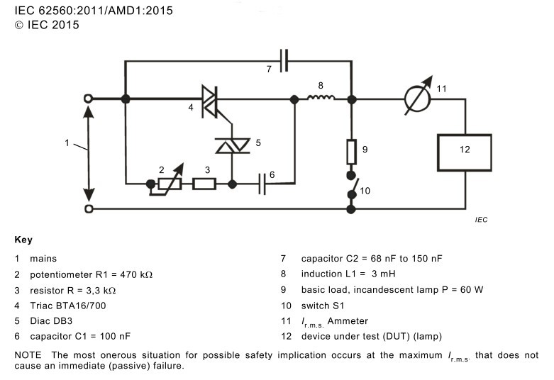
Gambar-3 1
3.2 Foto Produk
Lihat Gambar 3-2.
| Jumlah | Note |
| ① | Kabel Listrik |
| ② | Power receptacle; required to connect the luminaire under test to a suitable power source. Corresponds to Standard Figure No. 1 |
| ③ | Ammeter connection point, real-time measurement. Corresponds to standard drawing No. 11. |
| ④ | Connection point of the luminaire under test. Corresponds to figure 12 in the standard. |
| ⑤ | Base load, incandescent lamp, P=60W. Corresponds to standard diagram No. 9 |
| ⑥ | Switch S1. Corresponds to figure 10 in the standard drawing. |
| ⑦ | Potentiometer R1 = 470 kΩ. Corresponds to standard drawing No. 2. |
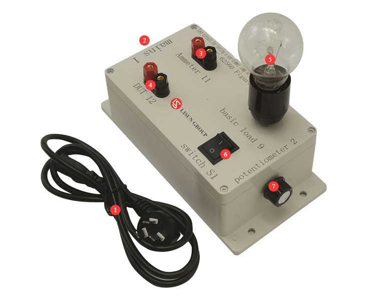
Gambar-3 2
4. Abnormal Operation Test for Non-Dimmable Lighting Fixtures
4.1 Persiapan Tes
4.1.1 Purpose of the Test
The lamp must not pose a hazard under abnormal operating conditions. The lamp must be designed to prevent fires and mechanical damage caused by abnormal conditions or improper operation from compromising protection against electric shock.
4.1.2 Pre-test Procedures
Refer to Section 3.2, install the base load (incandescent lamp), connect the ammeter, and connect the lamp under test.
Test the sample for spontaneous ignition at room temperature and the rated voltage, and check whether it meets the requirements either directly above the lamp head or at the ignition point indicated on the packaging.
If a voltage range is specified, testing should be conducted at the average voltage of the specified range.
If the rated voltage is substituted, tests must be conducted separately for each rated voltage.
4.2 Prosedur Uji
4.2.1 Debugging Ir.m.s
Determine the positions of R1 (which can be adjusted by slowly turning the potentiometer knob) and S1 (which can be either on or off) that yield the maximum rms value of Ir.
When conducting tests under these conditions, if the lamp under test fails passively within 60 minutes, repeat the test using the lower 10% of Ir.m.s. The lower limit of Ir.m.s should be set in the direction of decreasing potentiometer resistance.
Repeat this process until the system has been running stably for at least 60 minutes.
4.2.2 Test Monitoring and Evaluation of Results
Under the most unfavorable dimming level described above, operate the tested luminaire for 8 hours.
During this test, the lamp must not catch fire or emit flammable gases, and live parts must not be accessible to the Test Finger.
5. Prosedur Pasca-Ujian
5.1 Reset Perangkat
Turn off the power to the equipment, tidy up the equipment, or replace the lamp under test to prepare for the next round of testing.
5.2 Persiapan Sampel
Pisahkan sampel yang lulus dan gagal uji, beri label dengan jelas, dan hindari mencampurnya.
5.3 Membersihkan dan Merapikan Lokasi Pengujian
After all tests are completed, use a lint-free soft cloth to wipe dust and debris from the surface of the equipment.
Organize the tools and weights on the workbench, arrange them neatly, and clean up any debris generated during the experiment.
6. Pemeliharaan dan Perawatan Rutin Peralatan
6.1 Perawatan Rutin Mingguan
Check all terminal blocks one by one. If any terminals show signs of verdigris or oxidation, sand them down with fine-grit sandpaper; this will prevent loose connections and arcing, which can accelerate component aging.
Spray a specialized potentiometer contact cleaner onto the potentiometer shaft and between the contacts; if the shaft is stiff, apply a small amount of silicone-based grease. Rotate the potentiometer back and forth through its full range of motion 3 to 5 times to eliminate contact sticking and resistance fluctuations.
Remove the incandescent bulb and clean any carbon residue or carbon deposits from the inside of the socket; visually inspect the filament for signs of blackening or brittleness. If the filament is worn out, replace it directly with a 60W incandescent bulb of the same specification; do not substitute with a bulb of a different rated wattage.
6.2 Maintenance During Long-Term Storage with the Equipment Shut Down
After the equipment has been powered off and regular maintenance has been completed, cover the entire unit with a dust cover and store it in a dry, well-ventilated warehouse; store incandescent light bulbs separately; power on the equipment for 30 minutes each month to prevent components from becoming damp and damaged.
6.3 Persyaratan Interval Kalibrasi
Untuk memastikan akurasi pengukuran dan keandalan operasional peralatan, disarankan agar peralatan tersebut secara berkala dikirim ke lembaga metrologi pihak ketiga yang berkualifikasi untuk kalibrasi. Interval kalibrasi yang disarankan adalah 12 bulan. Pengguna dapat menentukan interval kalibrasi spesifik berdasarkan frekuensi penggunaan, kondisi lingkungan, dan persyaratan sistem mutu.
7. Pemecahan Masalah dan Penyelesaian Masalah Umum
| Gejala Kesalahan | Kemungkinan penyebab | Prosedur |
| When slowly adjusting the potentiometer, the current fluctuates significantly. | Wear on the potentiometer contacts and oxidation of the internal carbon film cause the resistance to fluctuate when the potentiometer is turned. | See Section 6.2 on cleaning the potentiometer; if that does not work, replace it directly with a linear potentiometer of the same specification. |
| Oxidation and Loose Connections at Terminal Blocks | Refer to Section 6.2 to inspect and service all terminal blocks. | |
| C2 capacitor aging and leakage; capacitance drift | Ganti kapasitor | |
| L1: Loose inductor pin, minor internal short circuit in the coil | Re-solder the pins; if the inductor parameters are abnormal, replace the 3 mH inductor directly. | |
| The circuit current remains consistently high, the thyristor is getting very hot, and the fuse blows frequently. | BTA16 Thyristor Breakdown | With the power off, measure the terminals of the thyristor offline; if it conducts in both the forward and reverse directions, it is broken down—replace the BTA16/700. |
| C2 Capacitor Breakdown and Short Circuit | Remove C2 and check it; if it’s shorted, replace it immediately. | |
| Short Circuit in a 60W Incandescent Light Bulb | Disconnect the incandescent light bulb and test it separately; if the bulb is shorted or the socket is carbonized and causing a short circuit, replace the bulb and the socket. | |
| The loop current remains consistently low | DB3 Trigger Diode Performance Deterioration | Replace DB3 |
| C1: Reduced capacitance decay | Replace the 100 nF standard capacitor | |
| R Fixed Resistor 3.3 kΩ—Increased resistance, aging | Replace the 3.3k fixed resistor | |
| The internal resistance of a 60W incandescent bulb increases as the filament ages. | Replace with a brand-new 60W incandescent bulb |