
 Inggris
 中文简体
中文简体 Русский
 Español
 Português
 Türkçe
 العربية
 Deutsch
 Polski
 Italiano
 Français
 한국어
한국어 ไทย
ไทย Tiếng Việt
 日本語
日本語





























Alat Uji Kompresi Casing Listrik
Pengguna manual
berlaku LISUN Model: LS-B21
1. Pemahaman Dasar tentang Peralatan
1.1 Parameter Utama
1.1.1 Spesifikasi Teknis Peralatan
| Parameter Teknis | Note |
| Metode Pengendalian | Touchscreen + PLC Control |
| Metode Kompresi | Listrik |
| Nilai Gaya Kompresi | 50–1000 N, adjustable |
| Akurasi Sensor | 1% FS |
| Compress Time | Adjustable from 1 to 99 minutes (seconds); once the compression time has elapsed, the system automatically releases pressure and retracts. |
| Resolusi Perpindahan | 1 mm |
1.1.2 Standar yang Berlaku
The LS-B21 Electrical Casing Compression Test Device strictly complies with GB/T 17466.1-2019″Electrical Accessories—Installation Boxes and Enclosures for Fixed Electrical Installations for Household and Similar Purposes—Part 1: General Requirements,” specifically Clauses 15.3 and 15.5 (IEC 60670-1:2021 Clauses 15.2 and 15.5), and is used to conduct testing.
It is primarily used in electrical appliance quality inspection laboratories, quality control departments of manufacturers, third-party testing organizations, and for import and export product inspections.
1.2 Verifikasi Konfigurasi Peralatan
1.2.1 Membongkar
Saat membuka kemasan perangkat, tangani dengan hati-hati untuk menghindari goresan pada casing luar dengan alat tajam. Setelah membuka kemasan, periksa terlebih dahulu bagian luar perangkat untuk memastikan tidak ada deformasi atau penyok yang terlihat, dan tombol-tombolnya tidak rusak atau longgar. Jika Anda melihat kelainan pada perangkat atau aksesorinya, jangan menyalakannya. Segera hubungi kami.
1.2.2 Unit Utama dan Aksesoris
| Jumlah | Note |
| ① | LS-B21 Compression Test Device Main Unit |
| ② | Kabel Listrik |
1.2.3 Mengunduh Dokumen Elektronik
We have already sent download links for the electronic user manual, calibration certificate, warranty card, and other documents via email at the time of shipment. Please download them promptly. If you missed the email, you may also contact us directly to request the download links again.
2. Tindakan Pencegahan Keamanan
2.1 Keamanan Listrik
Before connecting the power cord, verify that the supply voltage is AC 220 V ± 10% and the frequency is 50 Hz or 60 Hz;
You must use a three-prong outlet with a protective ground, with a protective ground resistance of ≤4 Ω. Under no circumstances should you cut or disconnect the protective ground wire, as doing so poses a risk of electric shock.
2.2 Keselamatan Lingkungan
Do not use in environments with flammable or explosive substances, strong electromagnetic interference, high temperatures and humidity, or excessive dust levels;
Operating Environment: Temperature 5°C to 35°C, relative humidity ≤ 65% RH.
2.3 Prosedur Operasional
Improper operation can easily result in personal injury, equipment damage, and distorted test data; operators must thoroughly read this manual and strictly follow the procedures;
Remove jewelry before performing the procedure, tie back long hair, and do not wear loose-fitting clothing;
During the test, take precautions to prevent test specimen fragments from flying and causing injury;
During the test, do not extend your hands or tools into the fixture’s travel range to prevent crush injuries or accidents;
Operators must not leave their posts without authorization while the equipment is in operation; in the event of an abnormality, immediately shut off the power supply;
Do not perform tests that exceed the load capacity or stroke limit, and do not use damaged or non-standard fixtures.
2.4 Lainnya
Untuk hal-hal yang tidak tercakup dalam panduan ini, harap berhati-hati atau hubungi kami.
3. Ikhtisar Peralatan
Lihat Gambar 3-1.
| Jumlah | Note |
| ① | Power Cord Connection and Power Switch |
| ② | Touchscreen |
| ③ | Posisi Pemasangan Spesimen |
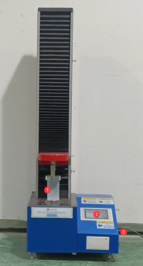
Gambar-3 1
4. Pengantar Program Layar Sentuh
4.1 Layar Awal
Lihat Gambar 4-1.
| Jumlah | Note |
| ① | Display current force, displacement, deformation, and maximum force |
| ② | If necessary, enter the sample information. |
| ③ | Test Plan Setup |
| ④ | Display Settings: You can set the units for force values. |
| ⑤ | Curve Display Area |
| ⑥ | Up/Down buttons: Manually adjust the size of the specimen mounting position based on the sample size. |
| ⑦ | Click to clear the current test data |
| ⑧ | Click to return the ram to its initial position |
| ⑨ | Stop Test Button, Start Test Button |
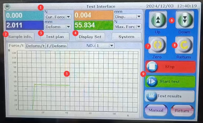
Gambar-4 1
4.2 Test Plan Interface
Lihat Gambar 4-2.
| Jumlah | Note |
| ① | To test the speed, you can use the default value. |
| ② | Break-induced shutdown: The machine automatically shuts down when the break reaches a set percentage. Optional feature |
| ③ | Test Type: The standard accessories included with this unit are intended for compression testing only. Please select “Compression.” |
| ④ | Start deformation calculation; calculation begins once the actual force reaches a specified percentage of the set force value. Optional setting |
| ⑤ | Shutdown conditions, optional pressure values. Optional settings |
| ⑥ | Start the crush test; once the actual force reaches a certain percentage of the set force, begin calculating the fracture ratio. Optional setting |
| ⑦ | Paksa Pengaturan |
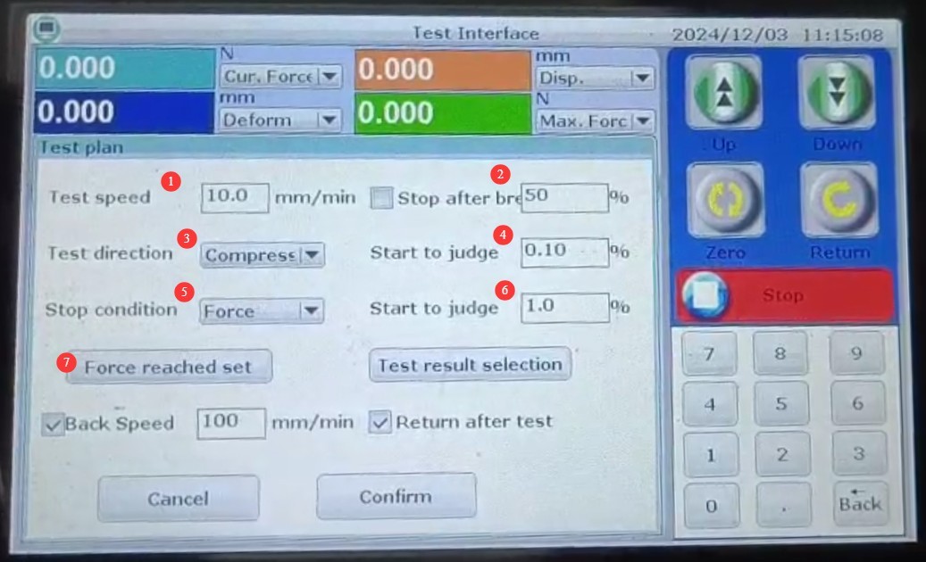
Gambar-4 2
4.3 Force Value Settings Screen
Lihat Gambar 4-3.
| Jumlah | Note |
| ① | Set the required force value |
| ② | Set the pressure duration |
| ③ | Speed reduction settings: When the pressure reaches a set percentage, the speed slows down. Use the default values. |
| ④ | Pressure-activated timing start setting: Timing begins when the actual pressure reaches 100% of the set pressure value. |
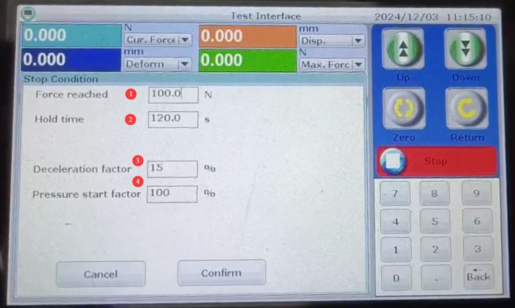
Gambar-4 3
5. Prosedur Uji Kompresi
5.1 Sample Preparation and Placement
Select a specimen of an electrical enclosure that is free of initial cracks, plastic deformation, and in perfect condition. Based on the specimen dimensions and in accordance with Section 4.1, use the up/down keys to adjust the platen to a position slightly higher than the specimen’s height, and place the specimen in the specimen mounting position as described in Chapter 3.
5.2 Pengaturan Parameter Uji
Set the compression force and duration in accordance with Section 4.3 and the relevant provisions of the standards.
Clause 15.3 of GB/T 17466.1-2019 (IEC 60670-1:2021 Clause 15.2) requires a force of 500 N applied for 1 minute; GB/T 17466.1-2019, Clause 15.5 (IEC 60670-1:2021, Clause 15.5) requires a force of 50 N/cm² (not exceeding 1000 N) to be applied through 9 mm thick plywood, with a duration of 1 minute.
5.3 Starting the Compression Test
| Jumlah | Note |
| ① | Click the “Start Test” button to begin the test |
| ② | Move the press block slowly toward the specimen and apply pressure. |
| ③ | When the actual pressure reaches the set value, the timer starts. |
| ④ | Once the force application time reaches the set duration, the test stops automatically and the load block returns to its original position. |
Note: If the actual pressure does not reach the set value, or if the specimen breaks during the compression process, you may click “Stop Test” to manually terminate the test.
5.4 Interpretasi Hasil Tes
After the test is completed, the mounting box and housing must not exhibit any deformation or damage that would affect continued use; if this is the case, the test is considered passed.
6. Pemeliharaan dan Perawatan Peralatan Harian
6.1 Perawatan Rutin
After each test, clean up any dust or debris from the specimen mounting area to keep the work surface clean and free of debris; wipe down the equipment surface to keep it clean; verify that the clamping block is secure and that the limit stops are not misaligned; apply specialized lubricant to the drive screw to ensure smooth operation.
6.2 Spesifikasi Penyimpanan
6.2.1 Persyaratan Lingkungan Penyimpanan
Suhu: 5°C hingga 35°C; kelembapan relatif: ≤65% RH; lingkungan kering, bebas debu, dan bebas dari gas korosif.
6.2.2 Operasi Penyimpanan Jangka Panjang
Matikan daya dan cabut semua kabel; bersihkan peralatan dan bungkus dengan plastik anti debu; hidupkan daya selama 30 menit setiap bulan untuk mencegah kerusakan akibat kelembapan pada komponen.
6.3 Persyaratan Interval Kalibrasi
To ensure the measurement accuracy and operational reliability of the equipment, it is recommended that it be sent periodically to a qualified third-party metrology laboratory for calibration. The recommended calibration interval is 12 months. The specific calibration interval may be determined by the user based on frequency of use, environmental conditions, and quality system requirements.
7. Pemecahan Masalah dan Penyelesaian Masalah Umum
| Gejala Kesalahan | Kemungkinan penyebab | Prosedur |
| The fixture does not raise or lower | Limit Switch Triggered | Check and adjust the limit switches |
| Force and displacement values are displayed incorrectly | Not reset to zero | Click to reset and try again |
| The machine stops as soon as the specimen is subjected to a load | Parameter Configuration Error | See Section 4.2; do not set unnecessary parameters arbitrarily. |