
 Inggris
 中文简体
中文简体 Русский
 Español
 Português
 Türkçe
 العربية
 Deutsch
 Polski
 Italiano
 Français
 한국어
한국어 ไทย
ไทย Tiếng Việt
 日本語
日本語





























Alat Uji Abrasi pada Selubung Isolasi Pin Steker
Pengguna manual
berlaku LISUN Model: LS-B10
1. Pemahaman Dasar tentang Peralatan
1.1 Parameter Utama
1.1.1 Equipment Technical Specifications
| Parameter Teknis | Note |
| Workstation | Stasiun tunggal |
| Frekuensi Gesekan | 30 times per minute; each forward and backward movement counts as one |
| berat | 4N |
| Jadwal kerja | 9 mm, with approximately 7 mm of friction-resistant insulation sheath |
| Scraping Wire | Φ1 mm, effective length 6 mm |
1.1.2 Standar yang Berlaku
The LS-B10 Apparatus for Abrasion Test on Insulating Sleeves of Plug Pins is designed and manufactured in strict accordance with Clause 24.8 and Figure 28 of GB/T 2099.1, “Plugs and Sockets for Household and Similar Purposes—Part 1: General Requirements” (IEC 60884-1:2022, Clause 23.2, Figure 31).
It is primarily used in electrical product quality inspection laboratories, the quality control departments of manufacturers of plugs, sockets, and electrical accessories, third-party testing organizations, and for import and export product inspections.
1.2 Verifikasi Konfigurasi Peralatan
1.2.1 Membongkar
Saat membuka kemasan perangkat, tangani dengan hati-hati untuk menghindari goresan pada casing luar dengan alat tajam. Setelah membuka kemasan, periksa terlebih dahulu bagian luar perangkat untuk memastikan tidak ada deformasi atau penyok yang terlihat, dan tombol-tombolnya tidak rusak atau longgar. Jika Anda melihat kelainan pada perangkat atau aksesorinya, jangan menyalakannya. Segera hubungi kami.
1.2.2 Unit Utama dan Aksesoris
| Jumlah | Note |
| ① | LS-B10 Main Unit |
| ② | Kabel Listrik |
| ③ | 2 spare U-shaped steel wires |
1.2.3 Download Electronic Documents
Kami telah mengirimkan tautan unduhan untuk manual pengguna elektronik, sertifikat kalibrasi, kartu garansi, dan dokumen lainnya melalui email pada saat pengiriman. Mohon segera unduh. Jika Anda belum menerima email tersebut, silakan hubungi kami untuk meminta tautan unduhan lagi.
2. Tindakan Pencegahan Keamanan
2.1 Keamanan Listrik
Before connecting the power cord, verify that the supply voltage is AC 220V ±10% and the frequency is 50 Hz or 60 Hz. You must use a three-prong outlet with a protective ground, and the protective ground resistance must be ≤4 Ω. Never cut or disconnect the protective ground wire, as doing so poses a risk of electric shock.
2.2 Keselamatan Lingkungan
Do not use this equipment in environments with flammable or explosive substances, strong electromagnetic interference, high temperatures and humidity, or excessive dust levels. Place the equipment on a level, stable surface, leaving at least 0.5 m of operating space around it. Operating environment: temperature 5°C to 35°C, humidity ≤65% RH.
2.3 Prosedur Operasional
During the test loading process, do not reach into the area of the clamps or the motor drive mechanism to prevent pinching injuries; test specimens must be securely clamped, as specimens falling out or weights dropping during the test may damage the equipment; it is strictly prohibited to disassemble the equipment’s drive mechanism or replace weights with non-original ones.
3. Ikhtisar Peralatan
3.1 Diagram Standar
Lihat Gambar 3-1.
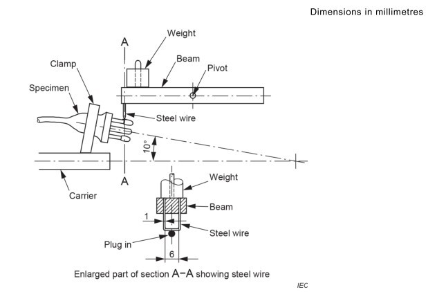
Gambar-3 1
3.2 Product Photos
Lihat Gambar 3-2.
| Jumlah | Note |
| ① | Saklar daya |
| ② | Sekering |
| ③ | Start Test Button |
| ④ | Stop Test Button |
| ⑤ | Tombol Reset |
| ⑥ | Counter: The top line displays the current number of tests, and the bottom line displays the set number of tests. |
| ⑦ | Motor drive rod and sensor: each full rotation is counted twice—once for each leg of the round trip. |
| ⑧ | Fixture for mounting the test specimen connector |
| ⑨ | Weight, 4 N |
| ⑩ | Kabel baja |
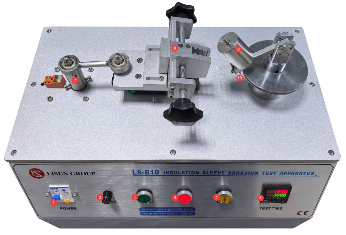
Gambar-3 2
4. Wear Resistance Test for Plug Insulation Sleeves
4.1 Persiapan Sampel
Select finished plugs that are intact, undamaged, and have not undergone aging tests. The test must be conducted on one prong of each test specimen.
4.2 Sample Installation and Commissioning
Refer to the standard diagram in Section 3.1 to install the test specimen. Press the “Start Test” button to begin the test, observe the wire’s friction travel, and adjust the position of the connector so that approximately 7 mm of the 9 mm wire travel is covered by the insulating sleeve. Once adjusted, press the “Stop Test” button, then press the “Reset” button to clear the count.
4.3 Set Parameters and Start the Test
| petunjuk | Note |
| ① | Press the counter setting button, then use the up and down buttons and the directional buttons to change the number of settings; according to the standard, the number of tests must be set to 20000. |
| ② | Press the Reset button to clear the current test data. |
| ③ | Press the “Start Test” button to begin the test. |
| ④ | During the test, observe the condition of the specimen and the steel wire. If any abnormalities are detected, press the “Stop Test” button, make the necessary adjustments, and then retry. |
| ⑤ | When the test is complete, the motor stops rotating; check the current test count to confirm that the test has been completed. |
4.4 Evaluasi Hasil Tes
After testing, the plug should show no damage that could compromise safety or affect future use; in particular, the insulated sheath should not be worn through or wrinkled.
5. Pemeliharaan dan Perawatan Rutin Peralatan
5.1 Daily Maintenance After Shutdown
At the end of each day’s testing, clean dust and specimen debris from the equipment surfaces, and keep the clamps and slide rails clean and free of debris; check the steel wire for looseness or deformation; if it is deformed or damaged, replace it.
5.2 Weekly Routine Maintenance
Apply a small amount of specialized lubricating grease to the equipment’s guide rails, drive screws, and bearings to ensure smooth, jam-free operation.
5.3 Maintenance During Long-Term Storage
After powering down and cleaning the equipment, apply rust-preventative oil to important components such as bearings, drive screws, clamps, and weights to prevent rust and deformation. Cover the entire unit with a dust cover and store it in a dry, well-ventilated warehouse. Power on the equipment for 30 minutes each month to prevent moisture damage to the components.
5.4 Persyaratan Interval Kalibrasi
To ensure the measurement accuracy and operational reliability of the equipment, it is recommended that it be sent periodically to a qualified third-party metrology laboratory for calibration. The recommended calibration interval is 12 months. Users may determine the specific calibration interval based on usage frequency, environmental conditions, and quality system requirements.
6. Troubleshooting and Resolving Common Issues
| Gejala Kesalahan | Kemungkinan penyebab | Prosedur |
| The device did not respond after the test was started. | Loose power cord, blown fuse | Check the input power supply and power cord connections; check the fuse on the front panel of the device; if it is blown, replace it with a fuse of the same rating. |