
 Inggris
 中文简体
中文简体 Русский
 Español
 Português
 Türkçe
 العربية
 Deutsch
 Polski
 Italiano
 Français
 한국어
한국어 ไทย
ไทย Tiếng Việt
 日本語
日本語





























Simulator Referensi Darat dan Offset Pasokan
Pengguna manual
berlaku LISUN models: LIS-OFFSET-10V10A
1. Pemahaman Dasar tentang Peralatan
1.1 Ikhtisar Produk
The LIS-OFFSET-10V10A Ground Reference and Supply Offset Simulator employs a four-quadrant bipolar power supply architecture with constant-voltage/constant-current dual modes, with a maximum output of ±10V/±10A and a bandwidth of 100 kHz. It is specifically designed for ground reference and power supply offset testing in automotive electronics, simulating potential difference conditions where multiple power supplies and ground paths coexist in a vehicle, and verifying the operational reliability of in-vehicle ECUs and components under potential offset conditions.
1.2 Standar yang berlaku
| Standar Jumlah | Standar Judul |
|---|---|
| GB/T 28046.2-2019, Klausul 4.8 | Environmental Conditions and Tests for Electrical and Electronic Equipment in Road Vehicles—Part 2: Electrical Loads |
| ISO 16750-2:2023, Clause 4.8 | Road Vehicles—Environmental Conditions and Testing for Electrical and Electronic Equipment—Part 2: Electrical Loads |
| Ford EMC-CS-2009.1, Clause 18.0 | Electromagnetic Compatibility Specification for Automotive Electrical and Electronic Components |
| BMW GS 95024 Bagian 5.1 | Komponen Listrik dan Elektronik pada Kendaraan Bermotor – Persyaratan dan Pengujian |
| Nissan 28400 | Spesifikasi Pengujian Komponen Listrik dan Elektronik Otomotif |
| FMC1278 CI 210 | Automotive Electrical and Electronic Test Standard |
2. Tindakan Pencegahan untuk Penggunaan
2.1 Persyaratan Lingkungan
Suhu lingkungan: 23 °C ± 5 °C; kelembapan relatif: 45–75%, tidak mengembun; ketinggian: ≤2000 m; tidak ada getaran kuat atau interferensi elektromagnetik di area sekitarnya; penggunaan peralatan di lingkungan berdebu, mudah terbakar, atau meledak dilarang keras.
2.2 Persyaratan Catu Daya
Input power supply: AC 220 V ±10%, 50 Hz; Input power: ≤1 kW; The power supply must be reliably grounded, with a grounding resistance of ≤4 Ω; It is recommended to use a voltage-stabilized power supply to prevent power grid fluctuations from affecting test accuracy.
2.3 Prinsip-prinsip Pengkabelan
Use power cables with the specified wire gauge to prevent overheating under high current conditions; keep test cables as short as possible and route them in parallel to minimize the impact of parasitic parameters; route signal and power cables separately to avoid cross-interference.
2.4 Pedoman Keselamatan Operasional
Wear insulated protective gear; before testing, ensure that all connections are secure and that there are no exposed conductors; Do not connect or disconnect test cables during testing to avoid arc burns; do not touch the DUT, test fixtures, or output terminals while the output is active to prevent the risk of electric shock from potential differences; if you hear unusual noises, smell an odor, or see smoke, immediately disconnect the power; during prolonged continuous testing, ensure the equipment is properly ventilated for heat dissipation.
2.5 Precautions for the Device Under Test (DUT)
All input and output ports of the DUT must be connected to representative analog vehicle loads and networks to simulate real-world vehicle operating conditions; the DUT must be configured in operating mode 3.4 as specified in ISO 16750-1, and its functional status must be monitored throughout the test; When multiple internal ground pins of the DUT are internally connected, the offset voltage must be applied simultaneously to all connected ground pins.
3. Ikhtisar Peralatan
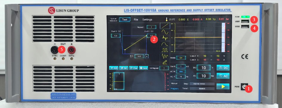
3.1 Panel depan
Lihat Gambar 3-1.
| Jumlah | Note |
|---|---|
| ① | Device Power Switch: Press briefly to turn on; press and hold to turn off. |
| ② | Layar Sentuh Kapasitif 10.1 inci |
| ③ | Port USB1: Digunakan oleh LISUN engineers for device debugging; users do not need to use it |
| ④ | Port USB 2.0, yang dapat digunakan untuk menghubungkan mouse untuk mengontrol layar sentuh, atau untuk menghubungkan flash drive USB untuk memperbarui perangkat lunak atau file basis data. |
| ⑤ | Output connector—pay attention to polarity |
3.2 Kembali Panel
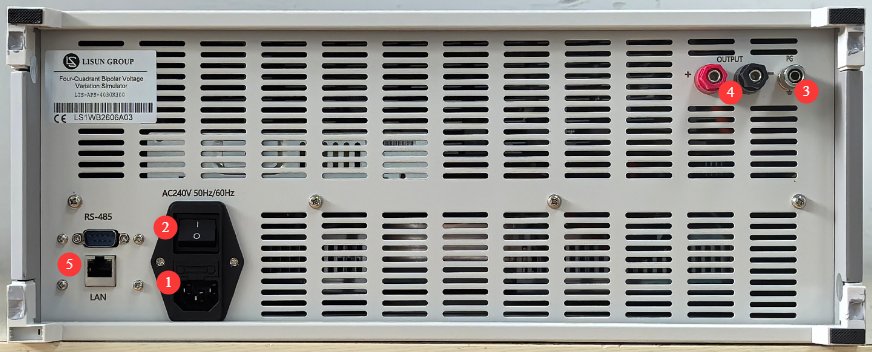
Lihat Gambar 3-2.
| Jumlah | Note |
|---|---|
| ① | Soket kabel daya dan sekering; pastikan catu daya input terhubung ke ground dengan benar. |
| ② | Pemutus sirkuit, sakelar daya utama untuk catu daya masukan peralatan. |
| ③ | Protective ground terminal: If the input power supply does not have a reliable ground connection, this terminal must be connected separately to ground. |
| ④ | Output jacks—pay attention to polarity; these function the same as the front-panel output jacks. |
| ⑤ | RS485 port/LAN port, which can be connected to a computer to use the host software (for backup purposes). The host software offers the same functionality as the touchscreen; please contact us if needed. |
4. Pengantar Program Layar Sentuh
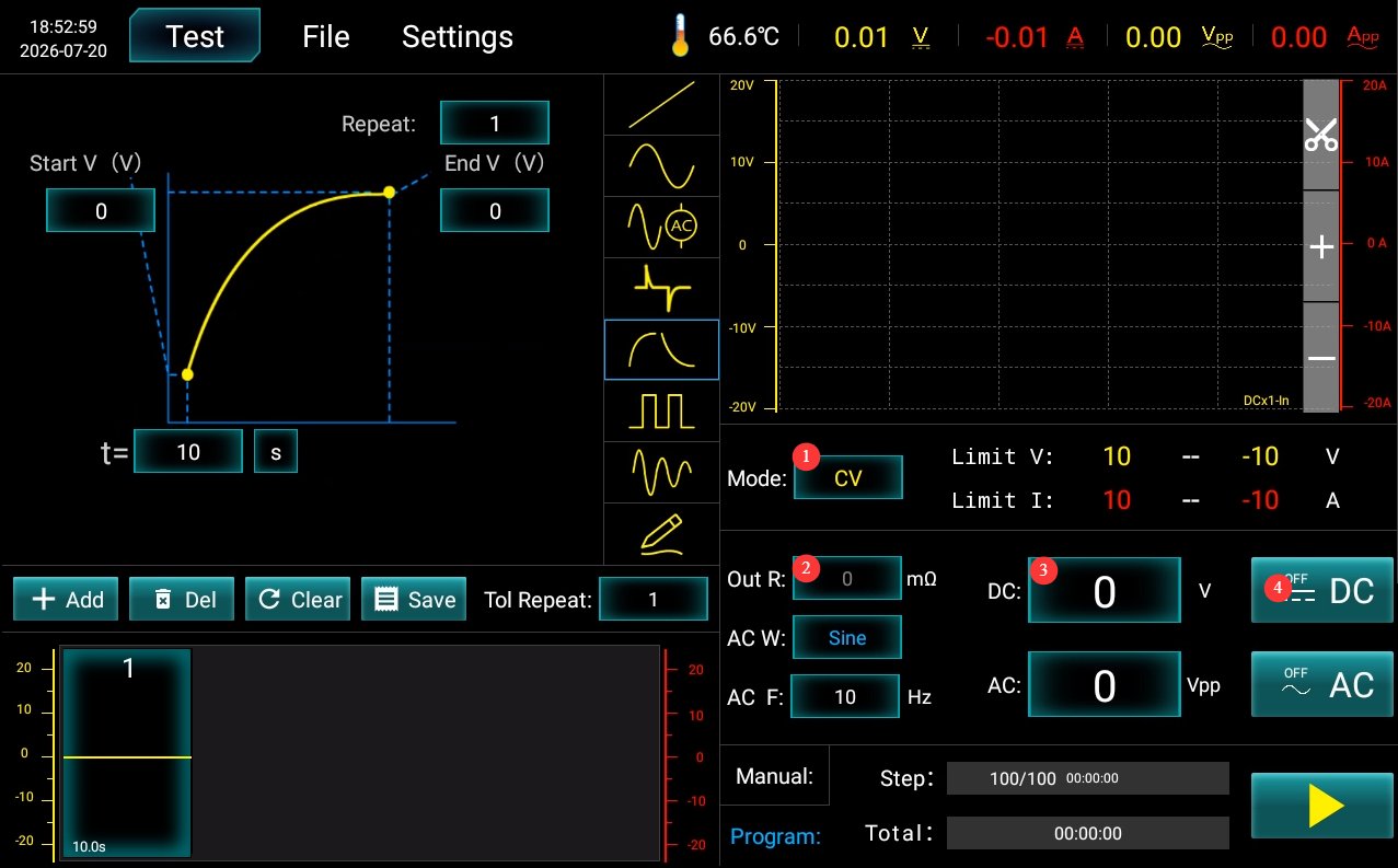
This device is essentially a four-quadrant bipolar power supply. For information on using the four-quadrant bipolar power supply program, please refer to the LIS-APS Operating Instructions. These instructions cover only the operations required when using the device as a Ground Reference and Supply Offset Simulator.
Lihat Gambar 4-1.
| Jumlah | Note |
|---|---|
| ① | Set to CV (Constant Voltage) |
| ② | Output impedance is set to 0 |
| ③ | Set the offset voltage |
| ④ | Click to enable/disable the offset voltage output |
5. Ground Reference and Power Supply Offset Test
5.1 Verification of Test Conditions
Verify the DUT specifications: Confirm whether it is a 12V or 24V system; Verify the number and pin definitions of the DUT’s power and ground pins;
verify the auxiliary power supply: an external base power supply (typically 13.5 V for 12 V systems and 28 V for 24 V systems);
Verify the DUT load: Connect the DUT inputs and outputs to corresponding simulated loads to simulate the actual vehicle wiring harness network;
Verify test standard requirements: Confirm the hold time for each test condition, the operating mode required for the DUT, and the criteria for passing the test.
5.2 Hardware Wiring
See Figure 5-1 for the standard wiring diagram (taken from ISO-16750 2:2023, Figure 18).
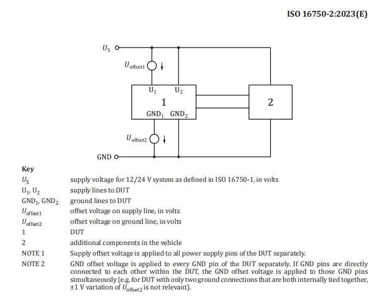
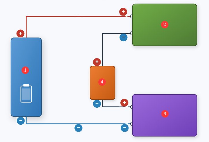
The LIS-OFFSET-10V10A is a single-channel device that must be used in conjunction with your LIS-AP device. Refer to Figure 5-2 for the wiring diagram; be sure to observe the polarity indicated in the diagram when making connections.
| Jumlah | Note |
|---|---|
| ① | Catu Daya Bantu |
| ②③ | LIS-OFFSET and LIS-AP have the same function and are used to simulate power supply offset and ground offset. ② is used to simulate the power supply offset Uoffset1, and ③ is used to simulate the ground (GND) offset Uoffset2. |
| ④ | DUT |
5.3 Explanation of the Standard Test Matrix for ISO 16750-2-2023
The table below lists the eight test conditions specified in the standard; typically, each condition must be maintained for 30 to 60 seconds to observe the DUT’s operating status.
| Test Conditions: Case | Power Supply Offset DC Output (Uoffset1) | Ground Offset DC Output (Uoffset2) | Deskripsi Tes |
|---|---|---|---|
| Kasus 1 | 0 V | 1V | 1 V GND offset, no power supply offset |
| Kasus 2 | 1V | 1V | 1 V GND offset, +1 V supply offset |
| Kasus 3 | -1V | 1V | 1 V GND offset, –1 V supply offset |
| Kasus 4 | 0 V | -1V | ‑1V GND offset, no power supply offset |
| Kasus 5 | 1V | -1V | ‑1V GND offset, +1V power supply offset |
| Kasus 6 | -1V | -1V | -1V GND offset, -1V power supply offset |
| Kasus 7 | 1V | 0 V | No GND offset, +1V supply offset |
| Kasus 8 | -1V | 0 V | No GND offset, -1V supply offset |
When the DUT has multiple independent power supply pins and multiple independent ground pins, each set power-ground loops must undergo a complete repetition of all 8 test cases; if multiple GND pins within the DUT are internally interconnected, the offset voltage must be applied simultaneously to all interconnected ground pins; All input and output load networks must match those of the actual vehicle; no no-load testing is permitted.
5.4 Evaluasi Hasil Tes
| Tingkat | Definition of Standards |
|---|---|
| Kelas A | During and after testing, all functions met the design specifications; there were no abnormalities and no out-of-tolerance conditions. |
| Kelas B | Functioned normally during testing, with only brief instances of parameters exceeding tolerance limits; automatic recovery from stress relief; storage function must be Grade A. |
| Kelas C | The test procedure allows for functional failures; normal operation is automatically restored after the offset voltage is removed. |
| Kelas D | Failed during testing; after the stress is removed, manual reset or a power cycle is required to restore operation. |
| Kelas E | Permanent damage; hardware needs to be repaired or replaced |
Note: Clause 4.8 of ISO 16750-2:2023 does not itself specify which class the DUT must meet, but this test typically mandates Class A.
6. Pemeliharaan dan Perawatan Peralatan Harian
6.1 Pembersihan harian
6.1.1 Jadwal dan Prosedur Pembersihan
Setelah setiap digunakanBersihkan permukaan layar sentuh dan hilangkan debu dari panel perangkat;
Mingguan: Clean the equipment housing and vent filters;
BulananBersihkan debu dari bagian dalam peralatan (harus dilakukan oleh profesional).
6.1.2 Metode Pembersihan
Wipe the exterior with a clean, soft, lint-free cloth; use a dedicated screen cleaner for the touchscreen; clean the vents with a soft-bristled brush and a vacuum cleaner if necessary; do not use corrosive solvents such as acetone.
6.2 Inspeksi Berkala
Check the power cord for damage or wear; check that the ground connection is secure; check that the fan is operating normally; check that the buttons and touchscreen are responsive; check the terminal blocks for oxidation or loose connections.
6.3 Penyimpanan dan penanganan
6.3.1 Persyaratan Penyimpanan Jangka Panjang
Storage Conditions: Temperature -10°C to +50°C, humidity ≤85%; Clean the equipment and apply dust protection before storage; Power on the equipment once every 3 months, running it for at least 30 minutes each time; Avoid stacking or applying heavy pressure to prevent the panel from warping.
6.3.2 Tindakan Pencegahan untuk Penanganan
Cabut semua kabel eksternal sebelum memindahkan perangkat; gunakan kemasan asli dan pastikan kemasan terlindungi dan diberi bantalan yang tepat; jaga agar perangkat tetap tegak selama pengangkutan dan hindari guncangan yang keras; saat mengangkat, pegang bagian bawah dan samping perangkat—jangan mengangkat dari panelnya.
6.4 Persyaratan Interval Kalibrasi
To ensure the measurement accuracy and operational reliability of the equipment, it is recommended that it be sent periodically to a qualified third-party metrology laboratory for calibration. The recommended calibration interval is 12 months. The specific calibration interval may be determined by the user based on frequency of use, environmental conditions, and quality system requirements.
7. Pemecahan Masalah dan Penyelesaian Masalah Umum
| Gejala Kesalahan | Kemungkinan penyebab | Prosedur |
|---|---|---|
| Perangkat tidak mau menyala | Saklar daya utama catu daya input di bagian belakang tidak dinyalakan, atau sekring putus. | Nyalakan sakelar catu daya input yang terletak di soket kabel daya di bagian belakang perangkat; periksa sekring, dan jika putus, ganti dengan sekring dengan nilai yang sama. |
| Kerusakan Layar Sentuh Setelah Dinyalakan | Sistem macet, kabel pita longgar | If the problem persists after restarting, disconnect the power, open the device’s casing, and check whether the touchscreen ribbon cable is loose. |
| Test Stopped Automatically Midway | Over-temperature protection triggered; overcurrent/overvoltage protection triggered | Check whether the equipment’s ventilation is obstructed and whether the ambient temperature is too high; check the DUT for short circuits or overloads. |
| USB Flash Drive Not Recognized | USB drive format is incompatible or has too much storage capacity | Gunakan drive USB berformat FAT32 dengan kapasitas tidak lebih dari 32 GB; jika masih tidak berhasil, coba drive USB lain. |
| No voltage/current after output is enabled | DUT Wiring Abnormality, Protection Function Triggered | After disconnecting the output, verify that the DUT is wired correctly and that there are no open circuits or short circuits; check for any overvoltage, overcurrent, or overtemperature warnings, and retry after resolving the issue. |
| Abnormal Output Voltage/Current Accuracy | Improper output resistance settings; long-term lack of calibration | Verify that the source impedance parameters meet the test requirements; contact a third-party metrology organization to perform calibration. |