
 Inggris
 中文简体
中文简体 Русский
 Español
 Português
 Türkçe
 العربية
 Deutsch
 Polski
 Italiano
 Français
 한국어
한국어 ไทย
ไทย Tiếng Việt
 日本語
日本語





























Simulator Hubungan Terbuka-Pendek pada Rangkaian Kabel Otomotif
Pengguna manual
berlaku LISUN models: LIS-LSCS-1730、LIS-LSCS-1750
1. Pemahaman Dasar tentang Peralatan
1.1 Klasifikasi Model
| LISUN Pilih Model | LIS-LSCS-1730 | LIS-LSCS-1750 |
|---|---|---|
| Jumlah Sakelar | Route 30 | Route 50 |
| Tegangan Maksimum | 60 VDC/220 VAC | |
| Maksimum Current | 10 A per channel, 50 A maximum for the entire unit | |
| On/Off Switches (S1) | <20 mΩ/10 A | |
| Short-Circuit Switches (S2/S3) | <20 mΩ/10 A | |
| Power Switches (S4/S5) | <5 mΩ/50 A | |
| Open-Circuit/Short-Circuit Trip Time | 20 ms–10000 detik | |
| Jumlah siklus | 1 – 10000 kali | |
| Number of Test Steps | Langkah 1–255 | |
| Konfigurasi Fitur | Full touchscreen, built-in standard library, voltage and current monitoring | |
| Control System | 10.1-inch Android Capacitive Touchscreen Display with Chinese and English Support | |
| Operasi Lingkungan | Temperature: 10–40°C; Humidity: 30%–70% | |
| Ukuran | 460 × 180 × 550 mm | |
| Berat | Tentang 8 kg | |
1.2 Compliance with Reference Standards
This equipment’s testing capabilities fully cover the requirements of the following international standards, national standards, and corporate standards of major automakers, and can be used directly for compliance testing under the corresponding provisions.
1.2.1 Standar Internasional dan Nasional
| Standard Number and Section | Judul Standar | Corresponding Test Items |
|---|---|---|
| GB/T 45120-2024, Klausul 10.15 | Road Vehicles—Electrical Requirements and Tests for 48-V Power Supplies: Short Circuits in Signal Lines and Load Circuits | 48V System Signal Line/Load Circuit Short-Circuit Test |
| GB/T 28046.2-2011, Clauses 4.9 and 4.10 | Environmental Conditions and Tests for Electrical and Electronic Equipment in Road Vehicles—Part 2: Electrical Loads | Open-Circuit Test / Short-Circuit Protection Test |
| ISO 16750-2:2023, Clauses 4.9 and 4.10 | Road Vehicles—Environmental Conditions and Testing for Electrical and Electronic Equipment—Part 2: Electrical Loads | Open-Circuit Test / Short-Circuit and Overload Protection Test |
1.2.2 Corporate Standards of Major Automakers
| Standard Number and Section | Judul Standar | Corresponding Test Items |
|---|---|---|
| JA 3700-MH-4-2021/2025, Section 4.20 | FAW Group Passenger Vehicle Electronic and Electrical Components: Electrical Environmental Specifications | Uji Hubungan Pendek |
| QLP YSY 0231-2024, Section 16.17 | Zhejiang Leapmotor Technology Co., Ltd. Corporate Standards | Short-Circuit Protection Testing for Signal Lines and Load Circuits |
| QSK J07.362-2024, Sections 5.17/5.20 | Electrical Test Methods for Saelis Electrical and Electronic Components and Subsystems | Connector Disconnection Test / Short-Circuit Test of Signal and Load Circuits |
| SMTC 3 800 001, Section 5.16 | SAIC Group General Testing Requirements for Electronic and Electrical Components | Short-Circuit Protection Testing for Signal Lines and Driver Circuits |
| VW 80000:2021/2022 E-17/E-20 | Test Specifications for Electrical Units in Vehicles Weighing Up to 3.5 metric tons | Signal and Load Circuit Short-Circuit Test / Reverse Power Feed-Through Test |
| VDS 28401-02 [4]:2025, Section 6.1.5 | Dongfeng Nissan General EMC Test Standard for E& E Components on the Test Bench: EQ/TE05 | Input/Output Port Short-Circuit Test to Power and Ground |
1.3 Skenario Aplikasi
The LIS-LSCS Series Automotive Wire Harness Open‑Short Simulator is a specialized testing device designed for automotive electronic and electrical testing and R& D. It can simulate standard test conditions—such as open circuits, short circuits, short circuits to the power supply, short circuits to ground, and connector disconnections—on signal lines and load circuits, meeting the stringent testing requirements for wiring harness reliability and protection performance set forth by GB national standards, ISO international standards, as well as the stringent testing requirements of major automakers regarding wiring reliability and protection performance. The equipment supports independent or synchronized control of multiple channels, allowing all tests to be completed with a single wiring setup, which significantly simplifies manual operations and improves testing efficiency and consistency.
1.3.1 Applicable Industries and Scenarios
Automotive OEMs: DV/PV validation of components, incoming quality sampling inspections, and electrical reliability testing; Automotive parts manufacturers: Factory-level reliability testing of wiring harnesses, controllers, and sensors; Third-party testing organizations: Automotive electronics compliance certification and standards conformity testing; Research and education: R& D in automotive electronics technology, as well as teaching and experimental demonstrations.
1.3.2 Subjek Uji
Complete low-voltage wiring harness assemblies and local wiring harness subsystems; input and output ports for various automotive controllers (BCM, ECU, VCU, BMS, etc.); wiring harnesses for in-vehicle sensors and actuators; and wiring harnesses for external components such as body electronics and in-vehicle entertainment systems.
2. Tindakan Pencegahan untuk Penggunaan
2.1 Persyaratan Lingkungan
Ambient temperature: 23 °C ± 5 °C; relative humidity: 45–75%, non-condensing; altitude: ≤2000 m; no strong vibrations or electromagnetic interference in the vicinity; the equipment must not be used in dusty or flammable and explosive environments.
2.2 Persyaratan Catu Daya
Input power supply: AC 220 V ±10%, 50 Hz; Input power: ≤1 kW; The power supply must be properly grounded, with a grounding resistance of ≤1 Ω; It is recommended to use a voltage regulator to prevent power grid fluctuations from affecting test accuracy.
2.3 Prinsip-prinsip Pengkabelan
Use power cables with the specified wire gauge to prevent overheating under high current conditions; keep test cables as short as possible and route them in parallel to minimize the impact of parasitic parameters; ensure that the DUT (Device Under Test) enclosure is reliably connected to the equipment’s protective ground; and route signal and power cables separately to avoid cross-interference.
2.4 Pedoman Keselamatan Operasional
Wear appropriate insulated protective gear; before testing, ensure that all connections are secure and that there are no exposed conductors; do not touch or connect/disconnect wiring harnesses or cables during testing; if you hear unusual noises, smell an unusual odor, or notice smoke, disconnect the power immediately; when conducting prolonged continuous testing, ensure adequate ventilation and heat dissipation for the equipment.
3. Gambaran Umum Peralatan dan Pengkabelan
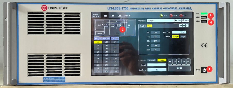
3.1 Panel depan
Lihat Gambar 3-1.
| Jumlah | Note |
|---|---|
| ① | Device power Switches: Press briefly to turn on, press and hold to turn off. |
| ② | Layar Sentuh Kapasitif 10.1 inci |
| ③ | Port USB1: Digunakan oleh LISUN engineers for device debugging; users do not need to use it |
| ④ | Port USB 2.0, yang dapat digunakan untuk menghubungkan mouse untuk mengontrol layar sentuh, atau untuk menghubungkan flash drive USB untuk memperbarui perangkat lunak atau file basis data. |
3.2 Kembali Panel
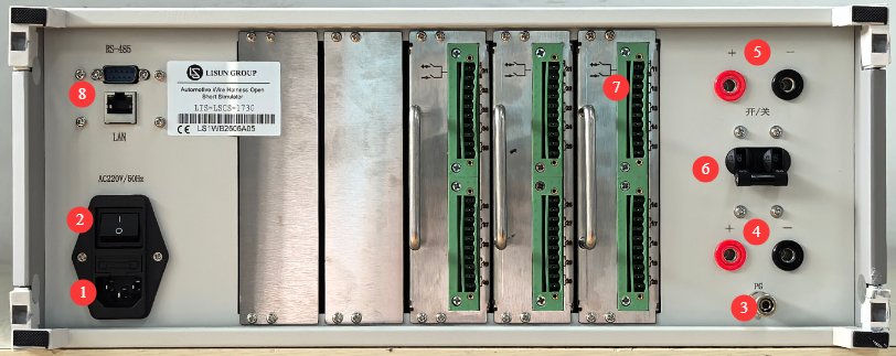
Lihat Gambar 3-2.
| Jumlah | Note |
|---|---|
| ① | Soket kabel daya dan sekering; pastikan catu daya input terhubung ke ground dengan benar. |
| ② | Pemutus sirkuit, sakelar daya utama untuk catu daya masukan peralatan. |
| ③ | Terminal pembumian pelindung: Jika catu daya masukan tidak memiliki koneksi pembumian yang andal, terminal ini harus dihubungkan secara terpisah ke pembumian. |
| ④ | Konektor Input Daya DUT: Catu daya eksternal yang sesuai harus disediakan untuk DUT. Anda dapat menggunakan LISUNGunakan catu daya empat kuadran seri LIS-APS, atau catu daya DC teregulasi lain yang sesuai untuk DUT. Perhatikan polaritasnya. |
| ⑤ | DUT power output connector; connect the DUT power cord here. Observe the polarity. |
| ⑥ | DUT Power Switches |
| ⑦ | Signal wire harnesses for continuity, short circuit, and connection testing; 30/50 channels total |
| ⑧ | Antarmuka RS485/port LAN, yang dapat dihubungkan ke komputer untuk menggunakan perangkat lunak host (untuk keperluan pencadangan). Perangkat lunak host menawarkan fungsionalitas yang sama dengan layar sentuh; silakan hubungi kami jika diperlukan. |
3.3 Pengenalan Aksesori
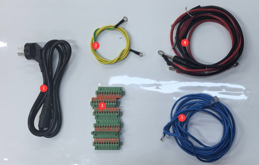
Lihat Gambar 3-3.
| Jumlah | Note |
|---|---|
| ① | Kabel Listrik |
| ② | Kabel tanah |
| ③ | Modul Koneksi Jalur Sinyal |
| ④ | DUT Power Supply Input and Output Cables |
| ⑤ | Kabel Ethernet, digunakan untuk menghubungkan komputer ke perangkat lunak host. |
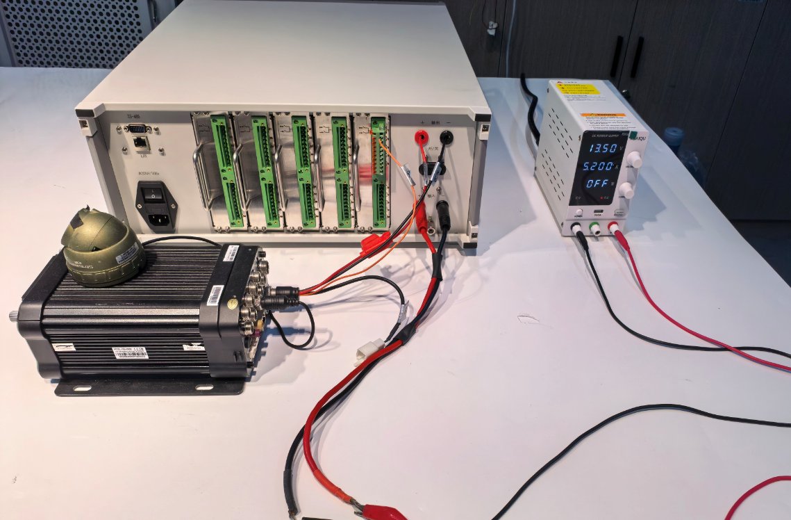
See Figures 3-4 for a schematic diagram of the external power supply and DUT connections:
See Figures 3-4 for a schematic diagram of the external power supply and DUT connections:
4. Pengantar Program Layar Sentuh
4.1 Antarmuka Pengujian
Lihat Gambar 4-1.
| Jumlah | Note |
|---|---|
| ① | Equipment Main Circuit Schematic |
| ② | Pilih saluran yang ingin Anda uji |
| ③ | Klik untuk menjalankan pengujian standar bawaan perangkat, atau pilih pengujian khusus. |
| ④ | Jika Anda memilih standar bawaan perangkat, semua parameter pengujian di area yang dibatasi warna merah telah dikonfigurasi sesuai dengan standar yang berlaku dan tidak perlu diubah; jika Anda memilih “Pengujian Kustom,” Anda dapat mengubah parameter pengujian. |
| ⑤ | For custom tests, you can save the configured test parameters to the device so they can be recalled later. |
| ⑥ | Waktu eksekusi ditampilkan dan dihitung secara otomatis; bilah kemajuan akan muncul untuk menunjukkan kemajuan pengujian setelah pengujian dimulai. |
| ⑦ | Switches for S1 through S5 have already been configured in the test parameters. However, if you need certain Switches to remain normally open during the test, you can manually click to close Switches corresponding switch before the test begins, ensuring it remains in the normally open state throughout the test. |
| ⑧ | JALANKAN: Setelah Anda memilih bentuk gelombang dan parameter lainnya, klik tombol ini untuk memulai pengujian. Selama pengujian, bilah kemajuan akan diperbarui setiap detik untuk menunjukkan kemajuan saat ini hingga pengujian selesai. Klik tombol ini lagi selama pengujian untuk menghentikan pengujian saat ini. |
| ⑨ | Display the DUT’s current voltage and current |
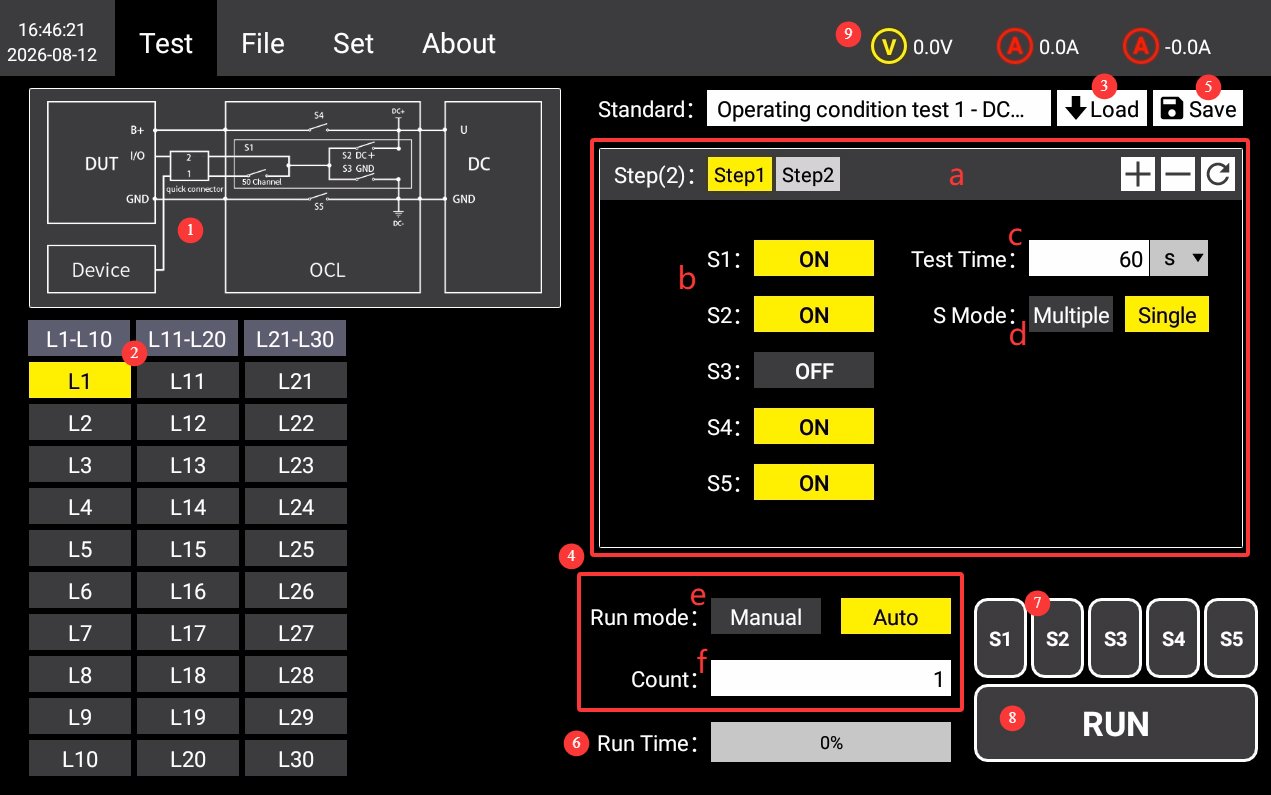
Test Parameter Overview: a) Add, delete, or reset test steps; Switches Switch status settings; c) Test duration; Switches: simultaneous or individual; e) Run mode: manual or automatic (in automatic mode, the system automatically proceeds to the next test step once the current one is completed); f) Number of cycles.
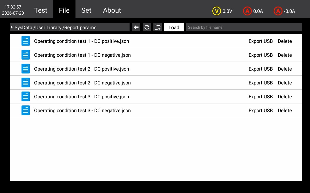
4.2 Antarmuka File Basis Data
Lihat Gambar 4-2.
| Jumlah | Note |
|---|---|
| ① | Test Plan Standard Library Management. You can manage the custom test parameters you have saved; please do not modify or delete the test parameters built into the device. |
| ② | If you have other standard tests but do not wish to create custom tests, please contact us and send us the details of the relevant standards. We will guide you through the process of updating the database file with those standards directly using a USB drive. |
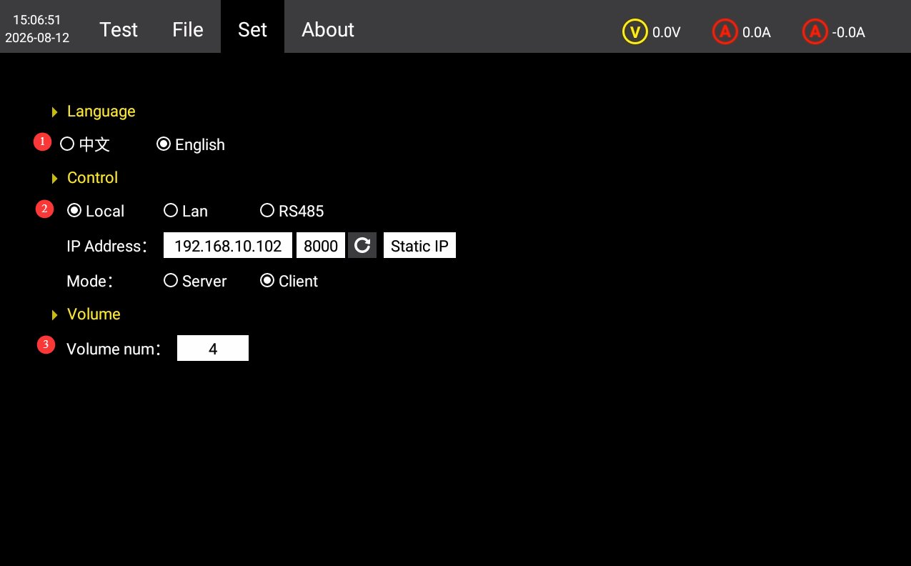
4.3 Antarmuka Pengaturan
Lihat Gambar 4-3.
| Jumlah | Note |
|---|---|
| ① | Beralih antara Bahasa Mandarin dan Bahasa Inggris |
| ② | Communication settings are set to “LOCAL” by default. If you need to use host computer software, you can switch to the RS485 or LAN port. Please contact us. |
| ③ | Pengaturan Volume |
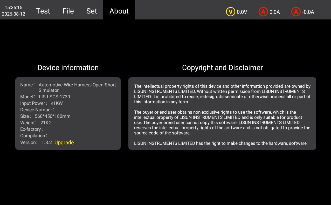
4.4 Tentang Antarmuka
For device information, firmware version, and copyright notice, see Figure 4-4.
5. Procedures for Conducting Continuity and Short-Circuit Tests on Automotive Wiring Harnesses
5.1 Prosedur Operasi Umum
5.1.1 Pengkabelan
Ensure that both the device and the DUT are powered off; use a test cable to connect the device’s DUT power output port to the DUT’s power cord; Use a cable to connect an external power supply (LIS-APS or other regulated DC power supply) to the DUT input power supply connector on the rear panel of the device; connect the DUT signal cables to the signal cable channels on the rear panel of the device using the dedicated terminals.
5.1.2 Pengaturan Parameter
Set the test parameters as described in Section 4.1, and select the channels you want to test.
5.1.3 Langkah-langkah Eksekusi Pengujian
Turn on the external power supply and connect it to the DUT; turn Switches on the back of the device and verify that the DUT is operating normally; on the touchscreen test interface, click the RUN button to start the test; observe the DUT’s operating status and record any observations; wait for the test to complete; in case of an emergency, you may press the stop button to halt the test immediately.
5.2 Typical Standard Test Conditions and Criteria for Acceptance
5.2.1 Open-Circuit Test (Corresponding to GB/T 28046.2, Section 4.9 / ISO 16750-2, Section 4.9)
Tujuan Tes: To verify the DUT’s functional behavior under open-circuit faults in signal and load lines, as well as its ability to recover after the fault is cleared.
Kriteria Lulus/Gagal: Grade A: All functions operate completely normally during and after testing, with no performance degradation; Grade B: Acceptable temporary degradation occurs during testing; functionality automatically recovers after the fault is resolved; Grade C: Functionality fails during testing but can be restored through manual reset or reboot, with no hardware damage; Grade D: Permanent hardware damage occurs and functionality cannot be restored; the unit is deemed to have failed the test.
The specific qualification levels are subject to the product’s technical specifications; key functions typically require a Grade B or higher.
5.2.2 Short-Circuit Protection Test (Corresponding to GB/T 28046.2, Clause 4.10 / ISO 16750-2, Clause 4.10)
Tujuan Tes: To verify the DUT’s ability to protect against short circuits between its ports and the positive power supply terminal or ground, ensuring there is no permanent damage or safety risk.
Kriteria Penerimaan: During testing, the protective mechanism triggered normally, with no smoke, fire, or melting of the housing; after testing, there was no permanent hardware damage, and functionality met the specified grade requirements; the protective device operated as designed, with no secondary failures; and the protective function remained effective upon retesting.
5.2.3 Short-Circuit Test for Signal Lines and Load Circuits in the 48V System (in accordance with GB/T 45120-2024, Clause 10.15)
Tujuan Tes: To verify the short-circuit protection performance of signal lines and load circuits for components in a 48V power supply system.
Persyaratan: A short circuit must not cause safety risks such as fire or loss of control; the protective circuit must operate reliably, and functionality must be restored after the fault is cleared; the low-voltage control section must not be affected by a short circuit and must maintain its basic functionality.
5.2.4 Connector Disconnection Test (in accordance with QSK J07.362-2024, Section 5.17, and other automotive industry standards)
Tujuan Tes: To simulate transient connector contact failures caused by vibration and verify the DUT’s immunity to interference and fault tolerance.
Kriteria Penerimaan: No system crashes, unexpected resets, or data loss may occur during testing; communication signals must not experience irrecoverable communication interruptions; after testing, all functions must operate normally, with no hidden damage.
5.3 Prosedur di Akhir Tes
Ensure that both the equipment and the DUT are powered off; disconnect the connections on the DUT side first, then disconnect the connections on the equipment side.
6. Pemeliharaan dan Perawatan Peralatan Harian
6.1 Pembersihan harian
6.1.1 Jadwal dan Prosedur Pembersihan
Setelah setiap digunakanBersihkan permukaan layar sentuh dan hilangkan debu dari panel perangkat;
Mingguan: Clean the equipment housing and the filters in the vents;
BulananBersihkan debu dari bagian dalam peralatan (harus dilakukan oleh profesional).
6.1.2 Metode Pembersihan
Wipe the exterior with a clean, soft, lint-free cloth; use a special screen cleaner for the touchscreen; clean the ventilation openings with a soft-bristled brush and a vacuum cleaner if necessary; do not use corrosive solvents such as acetone.
6.2 Inspeksi Berkala
Check the power cord for damage or wear; check that the ground connection is secure; check that the fan is operating normally; check that the buttons and touchscreen are responsive; check the terminal blocks for oxidation or loose connections.
6.3 Penyimpanan dan penanganan
6.3.1 Persyaratan untuk Penyimpanan Jangka Panjang
Storage Conditions: Temperature -10°C to +50°C, humidity ≤85%; Clean the equipment and apply dust protection before storage; Power on the equipment once every 3 months, running it for at least 30 minutes each time; Avoid stacking or applying heavy pressure to prevent panel deformation.
6.3.2 Tindakan Pencegahan untuk Penanganan
Unplug all external cables before moving the device; use the original packaging and ensure it is properly cushioned and protected; keep the device upright during transport and avoid harsh vibrations; when lifting, grip the bottom and both sides of the device—do not lift by the panel.
6.4 Persyaratan Interval Kalibrasi
To ensure the measurement accuracy and operational reliability of the equipment, it is recommended that it be sent periodically to a qualified third-party metrology laboratory for calibration. The recommended calibration interval is 12 months. The specific calibration interval may be determined by the user based on frequency of use, environmental conditions, and quality system requirements.
7. Pemecahan Masalah dan Penyelesaian Masalah Umum
| Gejala Kesalahan | Kemungkinan penyebab | Prosedur |
|---|---|---|
| Perangkat tidak mau menyala | Saklar daya utama catu daya input di bagian belakang tidak dinyalakan, atau sekring putus. | Nyalakan sakelar catu daya input yang terletak di soket kabel daya di bagian belakang perangkat; periksa sekring, dan jika putus, ganti dengan sekring dengan nilai yang sama. |
| Kerusakan Layar Sentuh Setelah Dinyalakan | Sistem macet, kabel pita longgar | If the problem persists after restarting, disconnect the power, remove the device’s outer casing, and check whether the touchscreen ribbon cable is loose. |
| Tes Berhenti Otomatis di Tengah Jalan | Over-temperature protection triggered, overcurrent/overvoltage protection triggered, external power interruption | Check whether the equipment’s ventilation is obstructed or whether the ambient temperature is too high; check the DUT for short circuits or overloads; check whether the external power supply has stopped outputting power. |
| USB Flash Drive Not Recognized | Format drive USB tidak kompatibel atau kapasitasnya terlalu besar. | Use a FAT32-formatted USB drive with a capacity of no more than 32 GB; if that doesn’t work, try a different USB drive. |