
 Inggris
 中文简体
中文简体 Русский
 Español
 Português
 Türkçe
 العربية
 Deutsch
 Polski
 Italiano
 Français
 한국어
한국어 ไทย
ไทย Tiếng Việt
 日本語
日本語





























Rak Uji Penuaan Driver LED
Pengguna manual
berlaku LISUN models: LEDRACK-1000W48P、LEDRACK-1000W48P-US、LEDRACK-100W192P,LEDRACK-100W192P-US、LEDRACK-300W120P、LEDRACK-300W120P-US、LEDRACK-500W96P、LEDRACK-500W96P-US、LEDRACK-60W240P、LEDRACK-60W240P-US
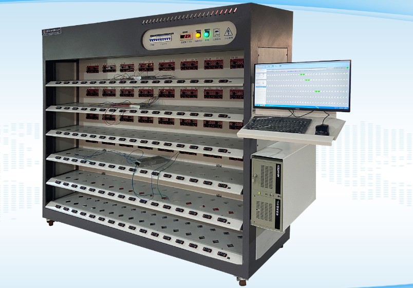
Below is an image showing the product’s overall appearance. Note: If you have customized the size or features of the aging rack, its appearance may vary slightly.
The computer components are packaged separately. Please install the computer tower, monitor, and other accessories in their respective slots on the burn-in rack. Connect them as shown in the two figures below.
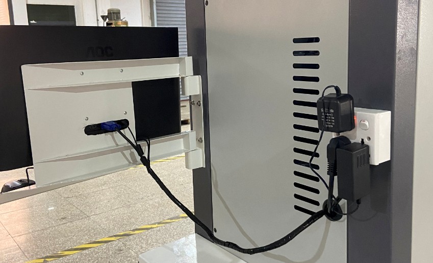
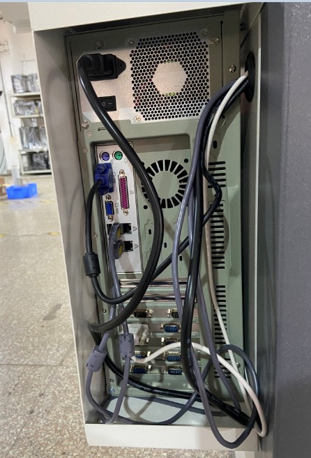
Connect the power cord for the aging rack at the top, as shown in the figure.
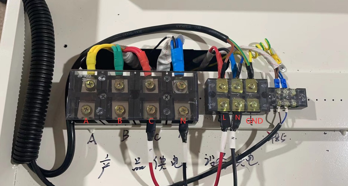
See the figure below. The left-hand side (A, B, C, N) provides power to the samples. Since the aging rack has a relatively high power consumption, three-phase power is used to reduce the load on the wiring. If you only have single-phase power and all samples use the same input voltage, you’ll need to use sufficiently thick wiring to short-circuit the three phases (A, B, C) together and supply power directly from a single phase. The supply voltage for the samples should match the voltage of the samples you are connecting. On the
right, L and N provide power to the equipment; the equipment requires only a single-phase 220V power supply.
GND is the ground wire; please ensure the equipment is properly grounded.
Note: When the unit is shipped from the factory, the sample power supply and the unit’s power supply may be short-circuited with a wire. If the sample and unit have the same voltage, they can share the same power cord. When using the unit, you may decide how to connect the power cords at both points based on your specific circumstances.
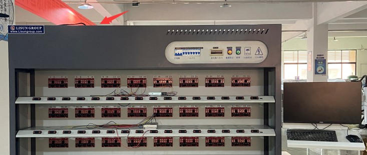
Note: If your aging rack is custom-built—for example, one capable of heating up to 80 degrees Celsius—the heating module requires three-phase power. See the figure below. In this case, the equipment must be connected to a three-phase power source.
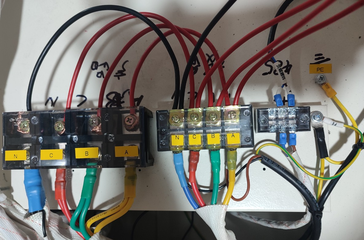
For specific details, please check the power terminals on your device. If you have any questions, please feel free to contact us.
1. System Usage
Install the sample driver as shown in the diagram below. Connect the AC input of the LED driver to the terminal marked = 1 * GB3① on the aging rack. Connect the DC output of the LED driver to the terminal marked = 2 * GB3② on the aging rack.
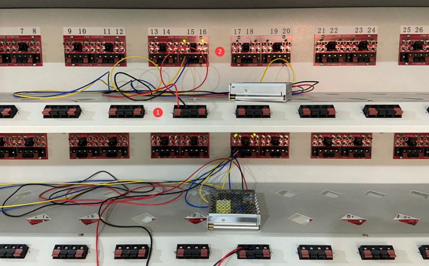
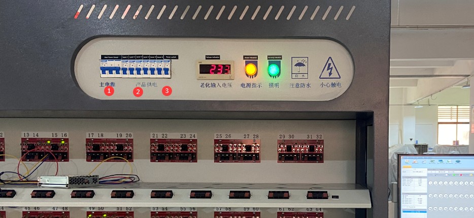
= 1 * GB3① is the main power switch for the aging rack. Turn on the main power switch. = 2 * GB3② is the individual power switch for each level of the aging rack. Turn on the power switch for the desired level. = 3 * GB3③ is the power switch for other equipment on the aging rack, such as computers. Turn on this switch. Then turn on the computer.
Open the aging rack software. Open System Settings.
Device Port Settings:
Test Results Save Location:
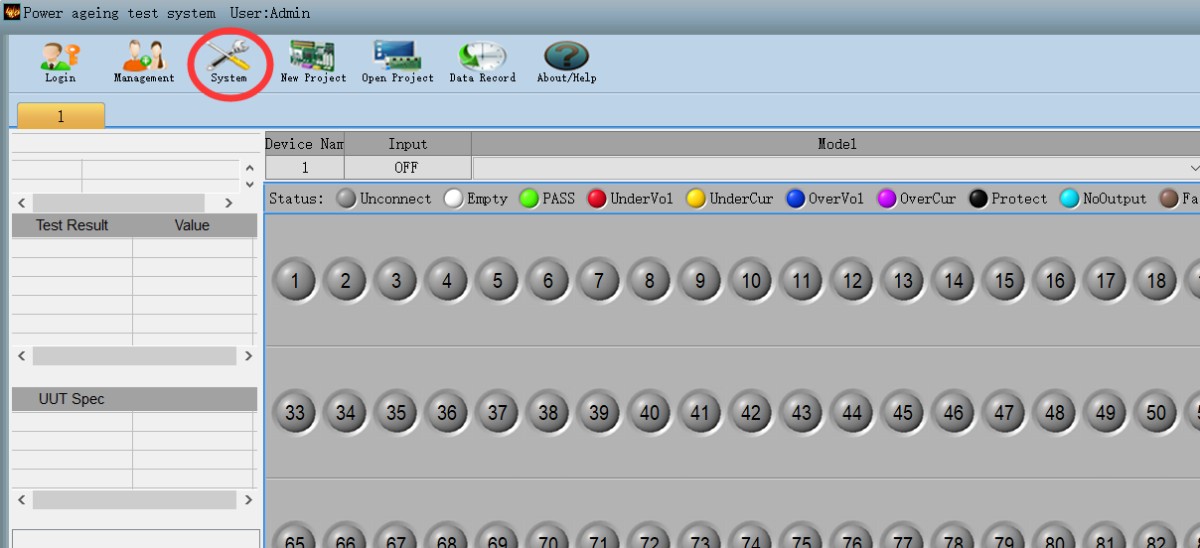
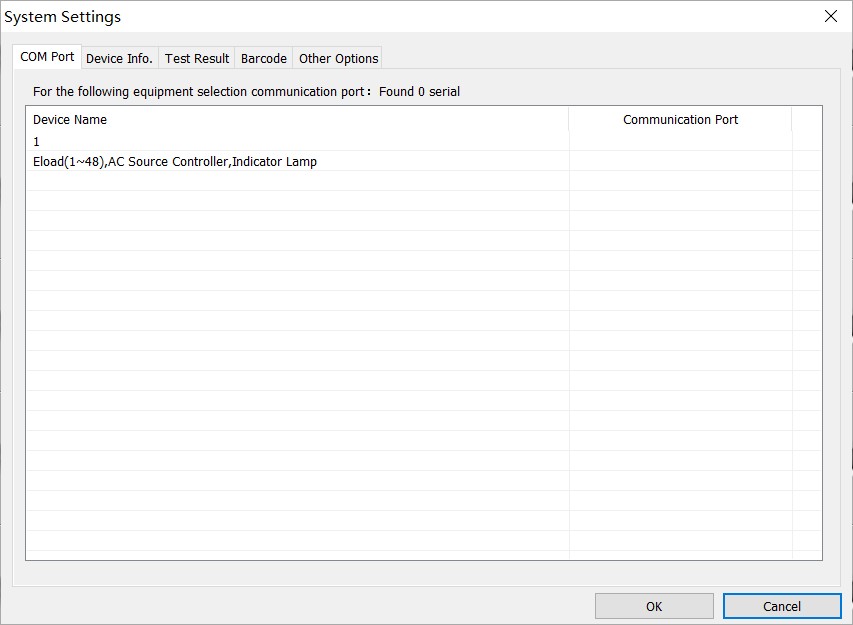
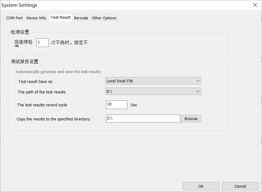
Create a new test project:
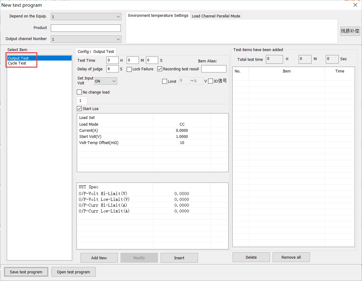
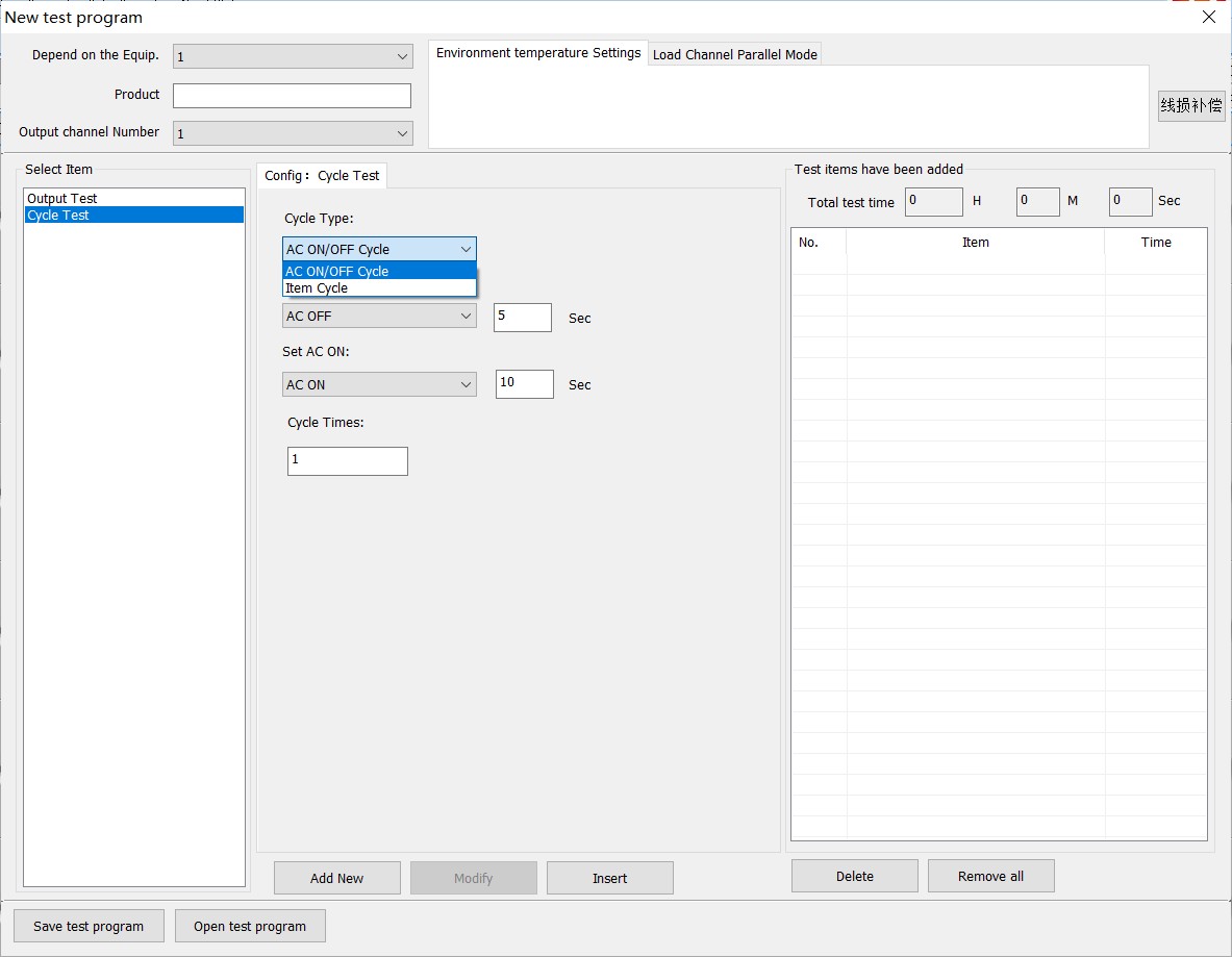
There are two types of tests: output tests and switching tests. For output tests, configure the total test duration, load mode and parameters, upper and lower limit values, and so on.
For switching tests, configure the corresponding switching times.
From this screen, you can save a test project file or open a previously saved test project file.

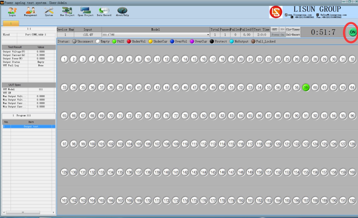
Click the “Test” button on the right side of the software interface to begin the test. The status of each sample station on the interface is indicated by color.
Daftar kemasan
| 1 | Aging Rack | 1 |
| 2 | Computers and Related Accessories | 1 |
| 3 | CD (includes a digital user manual, warranty card, certificates, etc.) | 1 |
Solusi Pengujian Kinerja Fotometrik, Kolorimetrik, dan Keamanan untuk LED
Sistem Goniofotometer: LSG-6000, LSG-1890B, atau LSG-1800ACCD
Sistem Uji Spektroradiometer & Bola Integrasi: LPCE-2 or LPCE-3
LED Life Memelihara Sistem Pengujian Sesuai dengan LM-84: LEDLM-84PL
Sistem Uji Keamanan Radiasi Fotobiologis: EN 62471-C atau EN 62471-P
Sistem Pengujian Penyalaan Lampu, Waktu Pengaktifan, dan Kedipan: LSRF-3 ke LSP-500VARC-Pst
Penguji Penggerak Daya LED: LS2090, M9822, dan LSP-500VARC
Penguji Tingkat IK | Penguji Dampak Palu Pegas: IK07-10, IK01-06
Sistem Pembangkit Getaran Elektrodinamik: LVD-100KG-6D
Alat Uji Keamanan Listrik: LS9955, ZRS-3H, ZY-3, TTC-1
Solusi Uji Ruang Lingkungan untuk Luminer LED
Uji Ketahanan Air untuk IPX5 dan IPX6: JL-56
Mesin Uji Tahan Debu untuk IP5X dan IP6X: SC-015
Ruang Suhu dan Kelembaban Tinggi dan Rendah: GDJS-015B
Mesin Uji Semprot Garam: YWX/Q-010
Ruang Uji Penuaan Lampu UV: UV-263LS
Ruang Uji Penuaan Lampu Xenon: XD-80LS
Kamar Uji Ozon: OTC-150A
Ruang Uji Sulfur Dioksida: SQ-010
Solusi Pengujian EMC dan EMI untuk Luminer CFL dan LED
Sistem Uji EMI: EMI-9KB or EMI-9KA
Simulator Pelepasan Muatan Elektrostatik: ESD61000-2
Pengukuran Kekebalan EFT: EFT61000-4
Pembangkit Lonjakan: SG61000-5
Generator Penurunan dan Gangguan Tegangan: CSS61000-11
Generator Gelombang Cincin: RWG61000-12

www. Lisungroup.com
Paten Diajukan
Seluruh Hak Cipta Dilindungi oleh Lisun Kelompok
Dapat Berubah Sewaktu-waktu Tanpa Pemberitahuan