
 Inggris
 中文简体
中文简体 Русский
 Español
 Português
 Türkçe
 العربية
 Deutsch
 Polski
 Italiano
 Français
 한국어
한국어 ไทย
ไทย Tiếng Việt
 日本語
日本語





























Perangkat Uji Defleksi/Tekuk Terminal Tanpa Sekrup
Pengguna manual
berlaku LISUN models: JCY-2
1. Membuka Kemasan dan Mengenal Peralatan Secara Dasar
1.1 Spesifikasi Teknis Utama
| Parameter Teknis | Note |
| Sudut tikungan | 0–360°, increment: 10° |
| Test Bending Direction | In each of the 12 directions, each spaced 30° ± 3° apart |
| Force Calibration Weights | 0.25 N, 0.5 N, 1.0 N |
| Arah Kekuatan | Perpendicular to the unbent wire |
| Jumlah stasiun kerja | Stasiun tunggal |
1.2 Membuka Kemasan dan Memeriksa Isinya
1.2.1 Membuka Kemasan dan Pemeriksaan Visual
Saat membuka kemasan perangkat, tangani dengan hati-hati untuk menghindari goresan pada casing dengan alat tajam. Setelah membuka kemasan, periksa terlebih dahulu bagian luar perangkat untuk memastikan tidak ada deformasi atau penyok yang terlihat, dan tombol-tombolnya tidak rusak atau longgar. Jika Anda melihat kelainan pada perangkat atau aksesorinya, jangan menyalakannya. Segera hubungi kami.
1.2.2 Unit Utama dan Aksesoris
| Jumlah | Note |
| ① | JCY-2 Threadless Terminal Bending Tester |
| ② | Weights: 1 each of 0.25 N, 0.5 N, and 1.0 N |
| ③ | Kabel Listrik |
Download links for the digital user manual, software, warranty card, and other materials have been sent via email. Please download them as soon as possible. If you missed the email, please feel free to contact us to receive the download links again.
1.3 Scope of Application of the Equipment
This equipment is designed in accordance with Clause 12.3.12 of GB/T 2099.1 (IEC 60884-1) and Clause 12.3.12 of GB/T 16915.1 (IEC 60669-1). The equipment simulates the bending stress that terminals may experience during actual wiring by applying bending forces of specific directions and magnitudes to the connected wires, thereby evaluating the terminals’ clamping ability and contact stability.
This manual refers to clause 12.3.12 of standard GB/T 16915.1 (IEC 60669-1). Please note this if you need to refer to other standards and the test requirements differ.
2. Tindakan Pencegahan Keamanan
2.1 Keamanan Listrik
2.1.1 Persyaratan Catu Daya
Use a single-phase AC 220 V ±10%, 50/60 Hz three-prong outlet; the ground prong must be connected to earth ground. Do not share the outlet with high-power equipment to avoid voltage fluctuations that could interfere with the test.
2.1.2 Persyaratan Pembumian
Kabel ground instrumen terhubung dengan andal ke kabel ground pelindung, dan resistansi ground pelindung ≤4 Ω.
2.2 Keselamatan Lingkungan
2.2.1 Persyaratan Suhu dan Kelembaban
Avoid using this product in environments where humidity exceeds 70% (without condensation) or where the temperature is outside the range of 0–35°C. The optimal operating temperature is 25 ± 2°C.
2.2.2 Kontraindikasi Lingkungan
Lingkungan dengan medan magnet yang kuat dan medan listrik yang kuat;
Lingkungan yang mengandung gas atau cairan korosif;
Area dengan debu yang mudah terbakar dan meledak, serta area yang mengandung bahan berbahaya;
Lingkungan dengan banyak debu, suhu dan kelembapan tinggi, serta sinar matahari langsung.
2.3 Keselamatan Operasional
Operators must be familiar with the instruction manual;
Do not reach into the area of moving parts with your hands or tools while the equipment is in operation;
Do not touch the wires, test specimens, or terminals while the test power supply is energized;
During testing, do not move the wires, test specimens, or measuring equipment, to avoid affecting the test results.
2.4 Lainnya
Untuk hal-hal yang tidak tercakup dalam panduan ini, harap berhati-hati atau hubungi kami.
3. Ikhtisar Peralatan
3.1 Tampilan Depan
| Jumlah | Note |
| ① | Saklar daya |
| ② | Buzzer: The buzzer will sound an alarm when the test is complete. |
| ③ | Touchscreen |
| ④ | Fixture used to secure test specimens with threadless terminals, ensuring no displacement or loosening during testing |
| ⑤ | berat |
| ⑥ | Weight slide rod, used to ensure that the force is applied perpendicular to the wire |
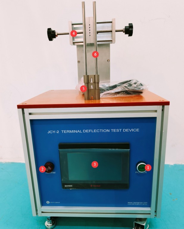
Gambar 1
3.2 Rear View
| Jumlah | Note |
| ① | Power Cord Jack |
| ② | Stepper Motor, Control Terminal Rotation Angle |
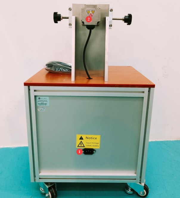
Gambar 2
4. Introduction to the Program Interface
4.1 Test Interface
| Jumlah | Note |
| ① Current number of bends | Real-time display of the number of bends completed |
| ② Preset number of bends | Customize the total number of bends |
| ③ Current wait time | Countdown to the Interval Between Two Bends |
| ④ Preset wait time | Customize the interval duration |
| ⑤ Single-bend angle | Customize the angle of each bend |
| ⑥ Current Location | Display the current angle in real time |
| ⑦Start/Stop | Start/Stop Test |
| ⑧Reset | Reset Test Data, Clear Alarms |
| ⑨CW | Motor (Fixture) Manual Forward Rotation |
| ⑩CCW | Manual Reversal of the Motor (Fixture) |
| ⑪Back | Motor (Fixture) Returns to Home Position |
| ⑫Zero | Set the current position of the motor (fixture) to 0° (reference position) |
| ⑬Home | Kembali ke Halaman Beranda |
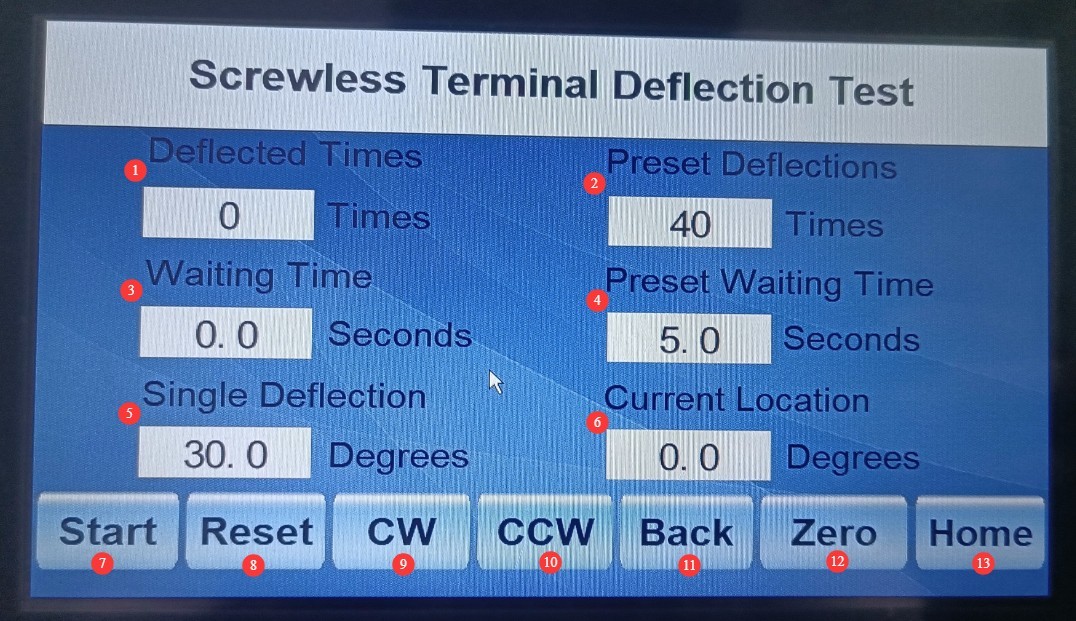
Gambar 3
4.2 Help Screen
Users may refer to the suggested testing process and precautions.
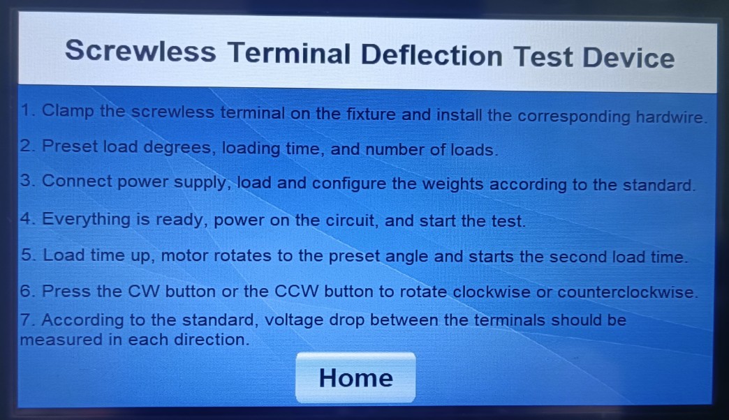
Gambar 4
5. Persiapan Sebelum Ujian
5.1 Preparation of Specimens and Consumables
5.1.1 Specimen Requirements
Three switch specimens that had not been tested were used.
Remove any parts that interfere with bending, while retaining the wire-guiding components.
5.1.2 Preparation of Test Leads
Use solid single-strand copper wire and test it immediately after stripping the insulation to prevent oxidation.
Select the cross-sectional area based on the switch’s rated current:
| Rated Current of the Outlet | First Order (Minimum Cross-Section) | Order 2 (Largest Cross-Section) |
| 1.0 mm² | 1.5 mm² | |
| 6 – 16 A | 1.5 mm² | 2.5 mm² |
5.2 Preparation of Auxiliary Equipment
Test power supply (the LISUN JCY-1 is an option), providing a continuous current with a fluctuation of ≤±5%.
Millivoltmeter (provided by the user), used to measure the voltage drop across the terminals.
5.3 Confirmation of Standard Test Parameters and Wiring Diagrams
5.3.1 Matching Wire Cross-Sectional Area to Force
| Nominal Cross-Sectional Area of the Wire | Bending Force Value | Corresponding weights |
| 1.0 mm² | 0.25 N | 0.25N weight |
| 1.5 mm² | 0.5 N | 0.5 N weight |
| 2.5 mm² | 1.0 N | 1.0 N weight |
5.3.2 Setting Parameters for the Bending Test
Set the angle for each bend to: 30.0°;
Bending direction: 12 directions, full coverage; that is, set the total number of bends to 12;
Wait time: Set according to test requirements (recommended: 5.0 s);
5.3.3 Power Supply and Millivoltmeter Wiring
Please also refer to the standard diagram below for the connection between the power supply (JCY-1) and the millivoltmeter.
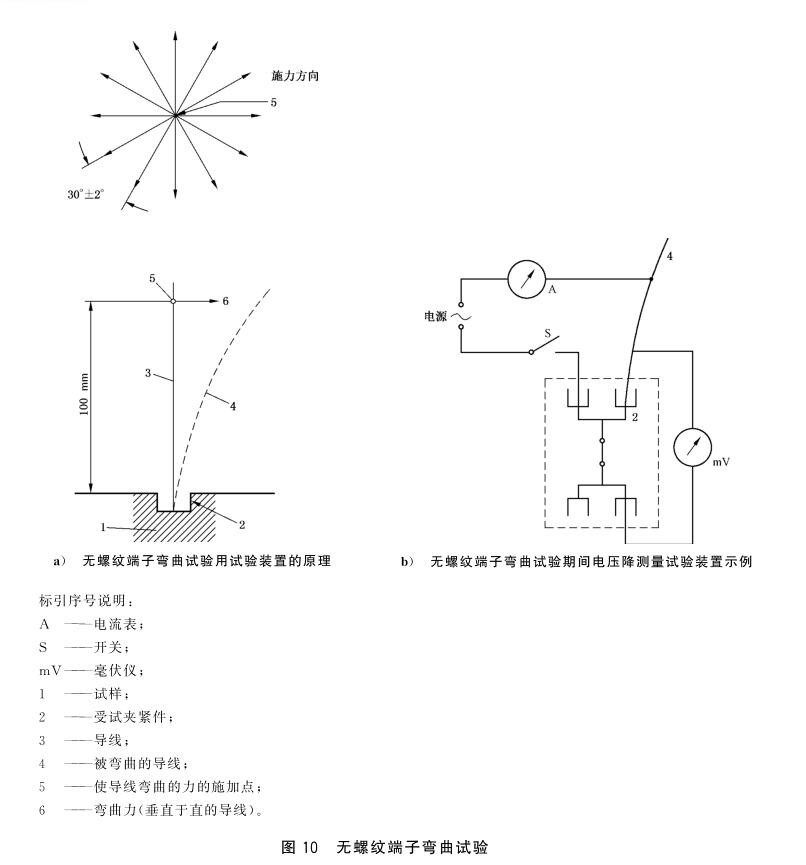
Gambar 5
6. Prosedur Uji
6.1 Sample Clamping
6.1.1 Wire Installation and Positioning
Prepare a solid single-core wire in the order specified in 5.1.2, insert it correctly into the threadless terminal, and tighten it according to normal operating requirements.
6.1.2 Terminal Clamping and Securing
Use the CW/CCW controls to manually adjust the fixture to the correct reference position, then click “Zero” to set it to 0°.
Securely clamp the threadless terminal in the equipment’s dedicated fixture to ensure there is no wobbling or displacement.
Position the wire horizontally so that it extends straight forward, passing through the weight slide rod, and ensure that the distance from the end of the terminal to the slide rod (the point of application of force) is 100 mm.
6.2 Loading Weights
6.2.1 Selection of Force Values
Select the appropriate weights in accordance with Section 5.3.1; mixing or misusing weights is prohibited.
6.2.2 Confirmation of Loading Location
Slowly slide the weight down the slide rod until it touches the wire.
6.3 Formal Testing Begins
6.3.1 Test Power Supply
Turn on the test power supply (JCY-1). Refer to the JCY-1 manual to ensure that the parameters on the JCY-1 touchscreen are set to provide a continuous current output. Click “Start,” then adjust the output current to the specimen’s rated current. Verify that the current is stable, with fluctuations of ≤±5%.
6.3.2 Uji Startup
Tap “Start” on the touchscreen, and the device will automatically perform the bending test according to the set angle, number of cycles, and interval.
6.3.3 Pemantauan Proses
Monitor the voltage drop reading on the millivoltmeter in real time and determine whether it meets the standard (the voltage drop should be ≤25 mV).
Monitored the angle, frequency, and wait time; the equipment is operating normally.
6.4 Other Steps
6.4.1 The voltage drop during the test met the requirements
If all tests in the first sequence are passed, select the wires for the second sequence in accordance with the standard (see 5.1.2) and continue with the testing.
After completing Test Specimen 1, when testing Specimens 2 and 3, manually adjust the fixture using the CW/CCW controls to the appropriate reference position. Ensure that the reference position angles for each specimen differ by 10°, then click “Zero” to set the angle to 0°.
6.4.2 Voltage Drop Did Not Meet Requirements During Testing
If the voltage drop in any of the 12 test directions exceeds 25 mV, continue applying force in that direction (i.e., click Start/Stop to halt the test, and the fixture will stop rotating) until the voltage drop falls below 25 mV; however, the force application time must not exceed 1 minute. After the voltage drop falls below 25 mV, continue applying force in that direction for 30 s; during this 30-second period, the voltage drop should not increase (then click Start/Stop to resume the test).
If a test specimen fails the test in any direction in which the test force is applied, the test shall be repeated on another set of specimens; during the retest, all specimens must pass.
7. Prosedur Pasca-Ujian
7.1 Termination of the Test
When the test is complete, or if you stop it manually, tap “Reset” on the touchscreen to clear the alarm messages and reset the test data.
7.2 Power Outage
Mengacu kepada JCY-1 instruction manual to turn off the power and disconnect the wires. If you are not continuing with the test, shut down the JCY-2, then remove the millivoltmeter leads, weights, test specimen, and wires.
8. Pemeliharaan dan Perawatan Peralatan Harian
8.1 Perawatan Rutin
Before turning on the equipment, check that the exterior is clean and free of damage;
After the test is complete, wipe down the surface of the equipment, the fixtures, and the test area of the specimen with an antistatic, dry cloth;
Keep the jaws of the fixture clean and free of wire debris and dust.
8.2 Penyimpanan Jangka Panjang
Jika perangkat tidak akan digunakan dalam jangka waktu lama, simpanlah di tempat yang kering dan berventilasi baik, jauhkan dari kelembapan dan sinar matahari langsung;
Apply a layer of rust-preventive oil to the surfaces of the fixtures and weights to prevent rust;
Disconnect all cables, store the accessories separately, protect the weights from impact, and cover the equipment with a dust-proof cloth;
Turn on the device for 30 minutes each month with no load to prevent the internal electronic components from deteriorating.
9. Pemecahan Masalah dan Penyelesaian Masalah Umum
| Gejala Kesalahan | Kemungkinan penyebab | Prosedur |
| The touchscreen is unresponsive | Power Supply Malfunction, System Freeze | Check the power supply to ensure it meets the requirements; restart the device and try again. |
| The motor does not rotate during the test. | Parameter Configuration Error | Check that the parameter settings are correct; make sure the angle and number of repetitions are not set to 0. |