
 Inggris
 中文简体
中文简体 Русский
 Español
 Português
 Türkçe
 العربية
 Deutsch
 Polski
 Italiano
 Français
 한국어
한국어 ไทย
ไทย Tiếng Việt
 日本語
日本語





























Perangkat Uji Tegangan Listrik dan Termal
Pengguna manual
berlaku LISUN Model: JCY-1
1. Unboxing and Basic Understanding of the Equipment
1.1 Spesifikasi Teknis Utama
| Parameter Teknis | Note |
| Uji Arus | 0 – 30 A |
| Setting the Number of Trials | 0 – 9999 kali |
1.2 Pemeriksaan dan Verifikasi Aksesori Saat Membuka Kemasan
1.2.1 Membuka Kemasan dan Pemeriksaan Visual
When unpacking the device, handle it gently to avoid scratching the exterior casing with sharp tools. After unboxing, first inspect the exterior of the device to ensure there is no visible deformation or dents, and that the buttons are not damaged or loose. If you notice any abnormalities with the device or its accessories, do not turn it on. Please contact us immediately.
1.2.2 Unit Utama dan Aksesoris
| Jumlah | Note |
| ① | JCY-1 Perangkat Uji Tegangan Listrik dan Termal |
| ② | Kabel Listrik |
Tautan unduhan untuk manual pengguna digital, perangkat lunak, kartu garansi, dan materi lainnya telah dikirim melalui email. Silakan unduh segera. Jika Anda melewatkan email tersebut, Anda dapat menghubungi kami untuk meminta tautan unduhan lagi.
1.3 Lingkup Penerapan Peralatan
Peralatan ini dirancang sesuai dengan Klausul 12.3.11 dari GB/T 2099.1 (IEC 60884-1) and Clause 12.3.11 of GB/T 16915.1 (IEC 60669-1). By applying a test current, the equipment simulates the electrical and thermal stress conditions that terminals encounter during actual use over a set cycle period and is capable of performing multiple cycle tests.
Manual ini mengacu pada klausul 12.3.11 dari standar GB/T 16915.1 (IEC 60669-1). Harap perhatikan hal ini jika Anda perlu merujuk ke standar lain dan persyaratan pengujiannya berbeda.
2. Tindakan Pencegahan Keamanan
2.1 Keamanan Listrik
2.1.1 Persyaratan Catu Daya
Gunakan stopkontak tiga cabang AC satu fasa 220 V ±10%, 50/60 Hz; cabang pembumian harus dihubungkan ke tanah. Jangan menggunakan stopkontak yang sama dengan peralatan berdaya tinggi untuk menghindari fluktuasi tegangan yang dapat mengganggu pengujian.
2.1.2 Persyaratan Pembumian
Kabel ground instrumen terhubung dengan andal ke kabel ground pelindung, dan resistansi ground pelindung ≤4 Ω.
2.2 Keselamatan Lingkungan
2.2.1 Persyaratan Suhu dan Kelembaban
Hindari penggunaan perangkat di lingkungan dengan kelembapan melebihi 70% (tanpa kondensasi) atau di mana suhu berada di luar kisaran 0–35°C. Suhu pengoperasian optimal adalah 25±2°C.
2.2.2 Kontraindikasi Lingkungan
Lingkungan dengan medan magnet yang kuat dan medan listrik yang kuat;
Lingkungan yang mengandung gas atau cairan korosif;
Area dengan debu yang mudah terbakar dan meledak, serta area yang mengandung bahan berbahaya;
Lingkungan dengan banyak debu, suhu dan kelembapan tinggi, serta sinar matahari langsung.
2.3 Keselamatan Operasional
Operators must be familiar with the instruction manual and wear insulating protective gear;
A dedicated staff member is on duty throughout the entire testing process to strictly prevent the risk of overheating and fire;
The output current can reach up to 30 A. Do not operate the device with wet hands, and do not touch the test specimen or the terminals during the test;
Do not cover the device’s cooling fan vents to ensure proper heat dissipation during operation;
Before connecting or disconnecting wires, you must stop the test, cut off the output current, turn the current knob to the minimum setting, wait until the discharge is complete (wait for at least 1 minute), then turn off the power before proceeding;
Current adjustment should only be performed after the test has been started via the touchscreen; full-scale adjustment under no-load conditions is prohibited;
Selama pengujian, jangan menggerakkan kabel, spesimen uji, atau peralatan pengukuran, untuk menghindari pengaruh terhadap hasil pengujian.
2.4 Lainnya
Untuk hal-hal yang tidak tercakup dalam panduan ini, harap berhati-hati atau hubungi kami.
3. Ikhtisar Peralatan
3.1 Panel Depan
| Jumlah | Note |
| ① | Saklar daya |
| ② | Touchscreen |
| ③ | Terminal blocks: Red—input terminal without threads; Black—output terminal; the two red and two black terminals can be short-circuited to split the current. |
| ④ | Jumper wires are intended solely for pre-shipment quality inspection; they must be replaced with test leads and non-threaded terminals before use. |
| ⑤ | The current adjustment knob may only be used after the screwless terminals have been properly connected and the “Start Test” button on the touchscreen has been tapped. |
| ⑥ | Buzzer: The buzzer will sound an alarm if the device’s output current is too high or when the test is complete. |
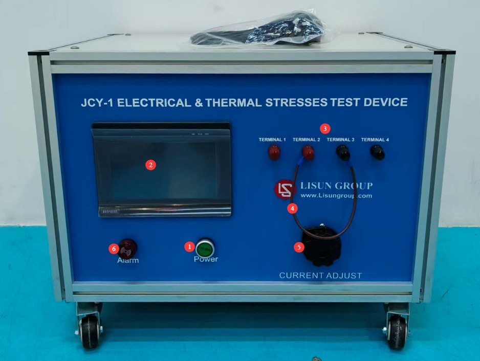
Gambar 1
3.2 Panel Belakang
| Jumlah | Note |
| ① | Soket Kabel Daya |
| ② | Cooling Fan |
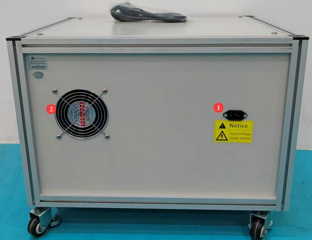
Gambar 2
4. Pengantar Antarmuka Program
4.1 Antarmuka Pengujian
| Jumlah | Note |
| ① Real-time power-on time | Current Test Power-On Duration |
| ② Preset power-on time | Customize the power-on duration (in minutes/seconds) |
| ③ Real-time power-outage duration | Current Test Power Outage Duration |
| ④ Preset power-off time | Customize the power-off duration (in minutes/seconds) |
| ⑤ Number of real-time on/off cycles | Number of cycles completed |
| ⑥ Preset number of on/off cycles | Customize the total number of cycles |
| ⑦ Real-time current measurement | Current output value (in A) |
| ⑧Start/Stop | Click to start/stop the test |
| ⑨Zero | Click to reset the current test data |
| ⑩Reset | When the device triggers an alarm, click to clear the alarm. |
| ⑪Home | Kembali ke Halaman Utama |
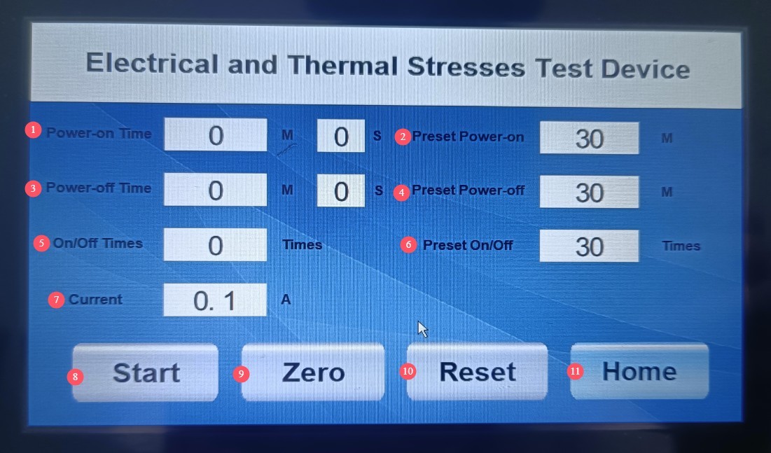
Gambar 3
4.2 Help Interface
Users may refer to the recommended testing procedures and precautions.
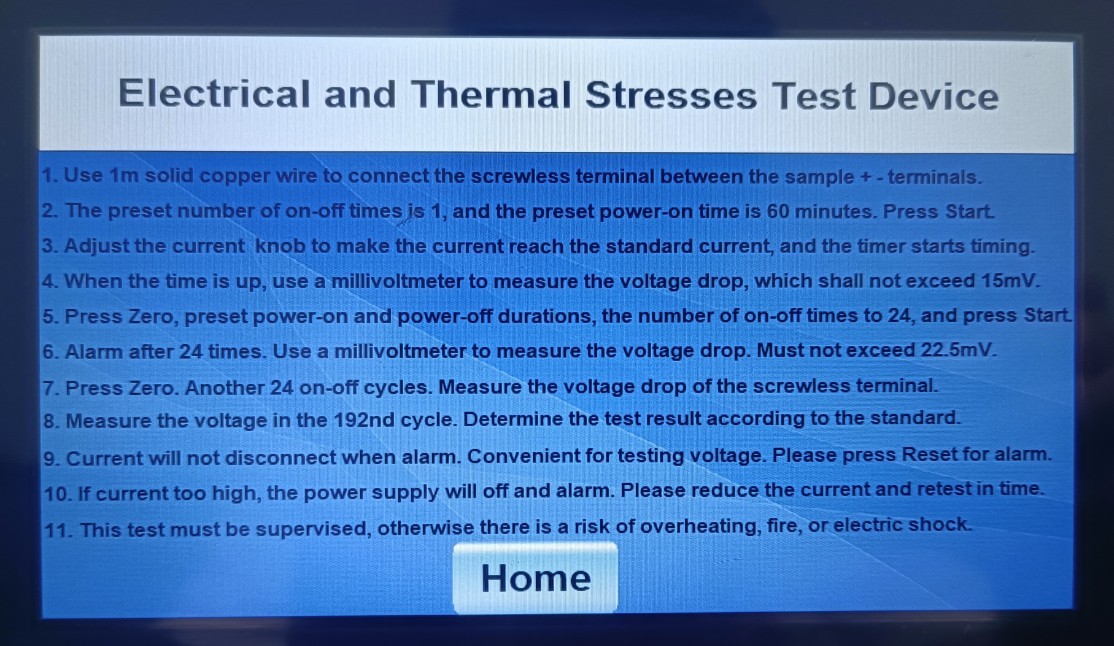
Gambar 4
5. Persiapan Sebelum Ujian
5.1 Verification of the Test Current for Test Specimen Leads
Test Specimens: 5 brand-new threaded terminals, free of damage or oxidation, rated for the same current as the socket
Select a new single-core solid copper conductor with a length of 1 m based on the rated current. Refer to the rated current of the screwless terminals to determine the test current and the conductor cross-sectional area, as shown in the table below.
| Nilai saat ini (a) | Arus Uji (A) | Wire Cross-Sectional Area (mm²) |
| ≤ 4 | 9 | 0.75 |
| >4 dan ≤6 | 13.5 | 1 |
| > 6 dan ≤ 10 | 17.5 | 1.5 |
| >10 dan ≤16 | 22 | 2.5 |
5.2 Preparation of Tools and Supplies
Tools to Bring: millivoltmeter (for measuring voltage drop), insulated screwdriver, wire strippers;
Supplies: Copper wire of the appropriate specifications, jumper wires.
5.3 Specifications for Test Specimen Wiring
Connect the input wire to the red terminal and the output wire to the black terminal on the screwless terminal block;
The wire should be stripped to an appropriate length and crimped securely to ensure a good connection.
6. Prosedur Uji
6.1 Electrical Stress Test (Step a)
| Prosedur | Note |
| ① | First, turn the current adjustment knob to the minimum setting, connect the test specimen, and verify that the connections are secure. |
| ② | On the touchscreen, enter the test interface and set the power-on time to 60 minutes, the power-off time to 0, and the number of power cycles to 1. |
| ③ | Click “Start” to begin the test, and turn the current knob to set the current to the standard test value. |
| ④ | Keep the power on for 1 hour; current flows only through the terminals, not through the outlet; do not move the wires or the test specimen at any time during the process. |
| ⑤ | After power-up, the device triggers an alarm, and the current continues to be output. |
| ⑥ | Immediately adjust the device’s output current from the test current at the threadless terminal to the rated current. |
| ⑦ | Use a millivoltmeter to measure the voltage drop across each threadless terminal. |
| ⑧ | Acceptance Criteria: A voltage drop of ≤15 mV is considered acceptable. |
6.2 Thermal Stress Cycling Test (Step b)
| petunjuk | Note |
| ① | After completing the electrical stress test, click “Zero” to reset the data; do not move the specimen or the wires. |
| ② | Parameter settings: Power on for 30 minutes, power off for 30 minutes, preset number of on/off cycles: 24. Click Start. |
| ③ | After completing the above 24 cycles, the device sounds an alarm, and the current remains at the output level. |
| ④ | Immediately adjust the device’s output current from the test current at the threadless terminal to the rated current. |
| ⑤ | Use a millivoltmeter to measure the voltage drop across the two ends of the threadless terminal and record the reading. |
| ⑥ | Repeat the above procedure to complete a total of 192 temperature cycles (measuring the pressure drop once every 24 on-off cycles). |
6.3 Evaluasi Hasil Tes
Voltage Drop Assessment: After every 24 cycles and after 192 cycles, the voltage drop must be ≤22.5 mV or ≤twice the value measured after 24 cycles (whichever is lower);
Visual Inspection: Upon visual inspection under normal lighting conditions, there are no cracks, deformations, melting, or other damage that would affect usability;
Mechanical Strength: After testing, the mechanical strength tests specified in Clause 12.3.10 of GB/T 16915.1 (IEC 60669-1) were repeated, and all test specimens met the requirements.
7. Prosedur Pasca-Ujian
7.1 Pengakhiran Tes
Setelah pengujian selesai, atau jika Anda menghentikannya secara manual, ketuk “Reset” pada layar sentuh untuk menghapus pesan alarm dan mengatur ulang data pengujian.
7.2 Pemadaman Listrik
First, turn the current adjustment knob to the minimum setting. After the discharge is complete (wait at least 1 minute), turn off the power. Then disconnect the millivoltmeter leads and the test specimen leads.
8. Pemeliharaan dan Perawatan Peralatan Harian
8.1 Perawatan Rutin
Sebelum menghidupkan peralatan, periksa terlebih dahulu apakah bagian luarnya bersih dan tidak ada kerusakan;
After the test is complete, wipe down the surface of the equipment and the test area of the specimen with an antistatic, dry cloth;
Check the equipment terminals for oxidation or burn marks; if any are found, wipe them with a specialized contact cleaner and replace the terminals if necessary;
Inspect jumper wires regularly; if they show no signs of overheating, aging, or damage, replace them promptly;
Check to see if the internal cooling fan is operating normally. If you hear unusual noises or if the fan is not running, please contact us immediately for repair.
8.2 Penyimpanan Jangka Panjang
Jika perangkat tidak akan digunakan dalam jangka waktu lama, simpanlah di tempat yang kering dan berventilasi baik, jauhkan dari kelembapan dan sinar matahari langsung;
Lepaskan semua kabel, simpan aksesori secara terpisah, dan tutupi perangkat dengan kain anti debu;
Turn the device on for 30 minutes each month to prevent the internal electronic components from deteriorating.
9. Pemecahan Masalah dan Penyelesaian Masalah Umum
| Gejala Kesalahan | Kemungkinan penyebab | Prosedur |
| The output current cannot be adjusted after the test is started. | Screwless terminals and wires are not properly connected | Please stop the test, check and confirm that the wiring is correct and secure, and then retest. The output current cannot be adjusted if the circuit is open. |
| A red message appears on the screen: “Excessive current!” accompanied by an alarm. | Overcurrent alarm; protection triggered due to excessive current | Immediately reduce the current and restart the test. |
| Touchscreen Lag | Kerusakan Catu Daya, Sistem Macet | Periksa catu daya untuk memastikan memenuhi persyaratan; mulai ulang perangkat dan coba lagi. |