
 Inggris
 中文简体
中文简体 Русский
 Español
 Português
 Türkçe
 العربية
 Deutsch
 Polski
 Italiano
 Français
 한국어
한국어 ไทย
ไทย Tiếng Việt
 日本語
日本語





























Perangkat Kalibrasi Palu Dampak Pegas
Pengguna manual
berlaku LISUN Model: IK01-07-CAL
1. Pemahaman Dasar tentang Peralatan
1.1 Parameter Utama
1.1.1 Specifications Table
| Parameter Teknis | Note |
| Calibrating the Impact Element | 250 g (pre-installed), 500 g (spare) |
| Rentang kalibrasi | 0–2 J |
| Pengulangan | ±0.01 J |
| Swinging the arm can cause damage | <0.002 J |
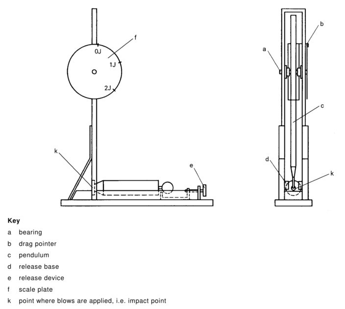
The equipment consists of three components: the main frame, the energy indication system, and the release positioning system. The overall structure complies with the requirements of Figure B.1 in Appendix B of GB/T 2423.55-2023 (IEC 60068-2-75:2014).
1.1.2 Structural Diagram
Equipment configuration, as shown in Figure B.1 of Appendix B of GB/T 2423.55-2023 (IEC 60068-2-75:2014). See Figure 1-1.
Gambar-1 1
1.2 Verifikasi Konfigurasi Peralatan
1.2.1 Membongkar
When unpacking the equipment, handle it gently to avoid scratching the exterior with sharp tools. After unpacking, first inspect the exterior of the main unit to ensure there are no obvious deformations, dents, or loose parts. If you notice any abnormalities with the equipment or accessories, please contact us immediately.
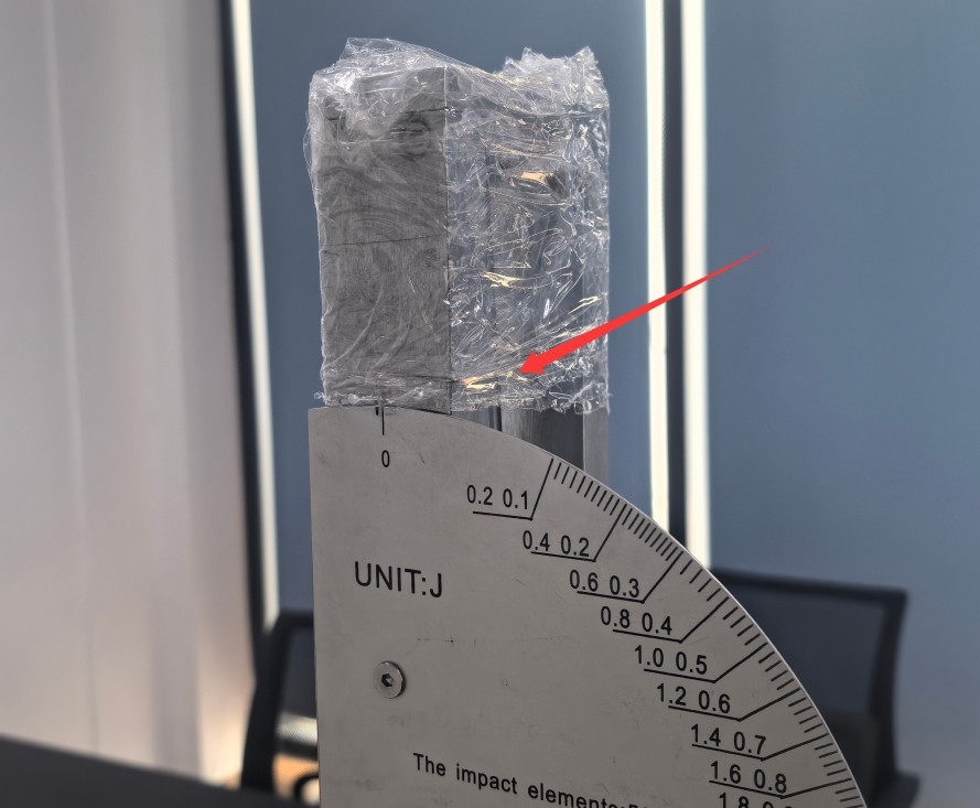
A piano wire with a pointer is installed at the location marked in the figure below. Please exercise special care when removing the packaging to avoid damaging it.
Gambar 1–2
1.2.2 Unit Utama dan Aksesoris
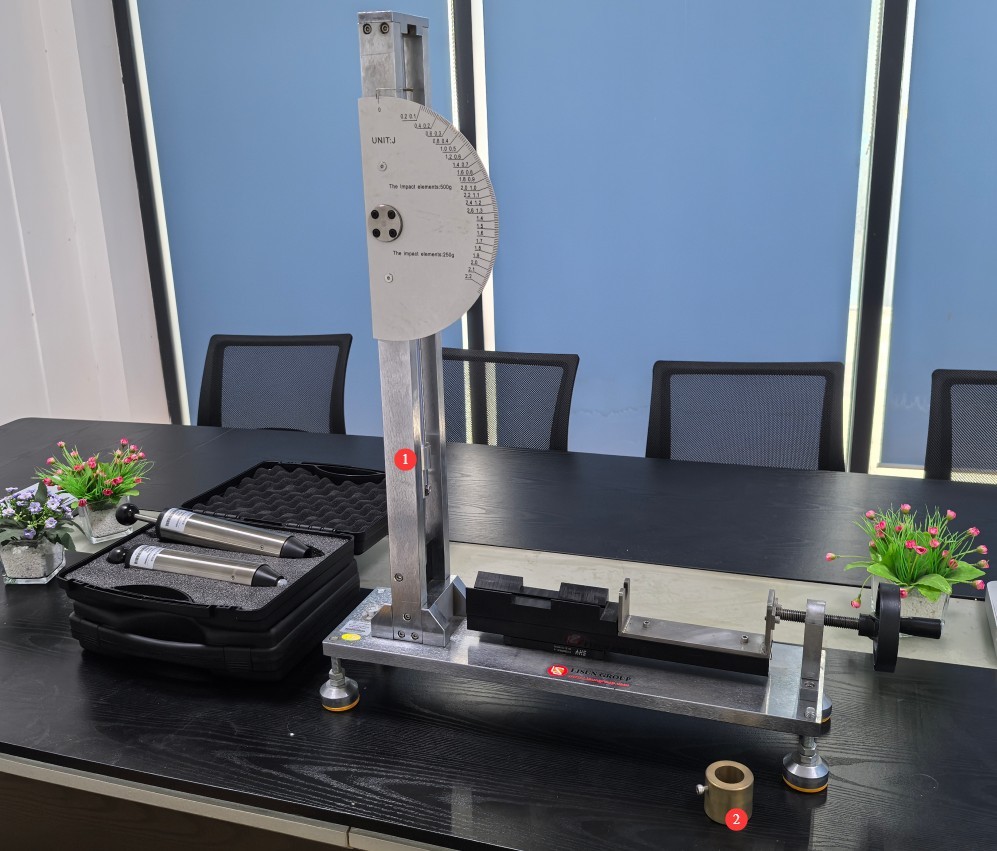
Lihat Gambar 1–3.
| Jumlah | Note |
| ① | The IK01-07-CAL Spring Impact Hammer Calibrating Device can be used to directly calibrate 250g impact elements. |
| ② | Used to calibrate the 500g impact element; for backup purposes; not required when calibrating the 0–2 J spring hammer. |
Gambar 1–3
2. Tindakan Pencegahan Keamanan
2.1 Pre-Operation Safety Requirements
Operators must be familiar with the entire contents of this manual; unauthorized operation without proper training is prohibited;
The equipment must be placed on a stable, level, and vibration-free surface. Use a spirit level to ensure it is level, and avoid tilting or wobbling;
It is strictly prohibited to disassemble the core components of the device (release mechanism, pendulum, and hands), and unauthorized adjustments to its structure are prohibited.
2.2 Safety Requirements During Operation
The spring-loaded impact hammer must be triggered via the equipment’s release mechanism; direct manual release of the impact hammer is strictly prohibited to prevent injury and damage to the equipment;
When operating the machine, keep your hands away from the impact zone and the area where the arm swings to avoid being pinched or struck;
After completing a single calibration, wait until the pendulum arm has come to a complete stop, reset the pointer to zero, and then proceed to the next operation.
3. Ikhtisar Peralatan
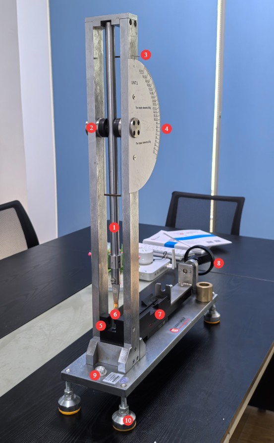
Lihat Gambar 3-1.
| Jumlah | Note |
| ① Arm swing c | Absorbs the impact of the hammer and transfers the energy to the hand |
| ② Bearing a | |
| ③ Pointer b | Indicates the impact energy value as the pendulum arm deflects |
| ④ Energy Gauge f | According to the text prompts on the energy dial, refer to the numbers on the outer ring to calibrate the 250-gram impact element; the unit is J. |
| ⑤ Release base d | Standard impact hammer with automatic trigger; manual release is prohibited. |
| ⑥ Impact contact point k | Impact hammer strike points, ensuring consistent force distribution |
| ⑦ Spring-loaded hammer slot | Secure the calibrated spring-loaded impact hammer to ensure precise positioning. |
| ⑧ Release mechanism (turntable) e | Push the spring-loaded hammer forward until the spring-loaded hammer is released and the base automatically releases. |
| ⑨ Spirit Level | Before using the equipment, make sure it is level and securely positioned. |
| ⑩ Footed glass | Four adjustable feet allow the device to be leveled |
Gambar-3 1
4. Calibration Test for the Spring-Loaded Impact Hammer
4.1 Installation and Alignment of the Impact Hammer
As shown in Figure 4-1, place the spring-loaded impact hammer—with the spring fully coiled—into the slot, ensuring it is securely fastened and does not wobble;
Rotate the turntable to align the impact hammer with the impact contact point k, ensuring precise positioning.
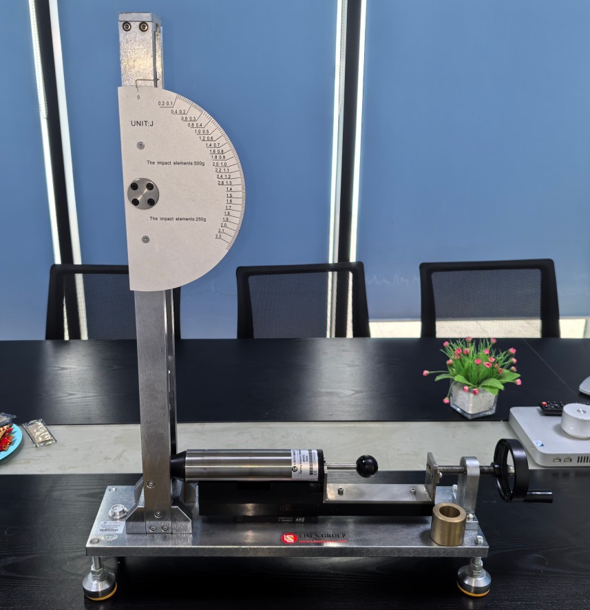
Gambar-4 1
4.2 Single Impact and Reading
Continue turning the dial to advance the impact hammer; the release mechanism on the base will automatically trigger the release of the impact arm. Do not release it manually;
As shown in Figure 4-2, after the pendulum arm swings to its maximum angle and returns, the pointer remains at its maximum deflection position. Read the value on the outer ring of the energy scale indicated by the pointer and record it as the first data point;
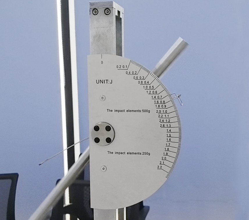
Gambar-4 2
Manually reset the pointer to zero, allow the swing arm to hang naturally, and reset the turntable before performing the next operation.
4.3 Three Standard Procedures
After completing the first test, rotate the impact hammer to a new position, repeat steps 4.1–4.2, and record the data from the second test;
Change the position of the impact element again, repeat the procedure, and record the data from the third test;
For all three operations, ensure that the installation, triggering, and reading conditions are consistent;
4.4 Data Recording and Calculations
Actual impact energy (J) = (1st reading + 2nd reading + 3rd reading) ÷ 3. Compare the calculated average to the impact hammer’s rated energy to determine whether the test passes.
5. Pemeliharaan dan Perawatan Peralatan Harian
5.1 Pembersihan dan Perawatan Harian
After each use, wipe down the device’s surface, energy dial, card slot, and release base with a clean, soft cloth to remove dust and grease;
Do not use corrosive solvents such as acetone to wipe the energy scale or the surface of the pointer;
Lubricate the rotating parts—such as bearings, swing arms, and the release mechanism (turntable)—with a small amount of special-purpose lubricant every 6 months to ensure smooth operation.
5.2 Periodic Inspection of Core Components
Pointers: Check monthly for deformation or looseness; if they cannot be reset, calibrate them promptly;
Release Mechanism (Turntable): Check monthly to ensure the trigger operates smoothly, with no jamming or looseness;
Swing Arm and Bearings: No deformation, no abnormal wear, and no resistance during rotation.
5.3 Long-Term Storage and Protection
When the equipment is not in use for an extended period, cover it with a dust cover and store it in a dry, well-ventilated, vibration-free environment;
Do not stack heavy objects on top of each other; do not store them together with sharp or hard objects;
Avoid direct sunlight to prevent the energy gauge from fading and components from deteriorating.
5.4 Persyaratan Interval Kalibrasi
Untuk memastikan akurasi pengukuran dan keandalan operasional peralatan, disarankan agar peralatan tersebut secara berkala dikirim ke laboratorium metrologi pihak ketiga yang berkualifikasi untuk kalibrasi. Interval kalibrasi yang disarankan adalah 12 bulan. Pengguna dapat menentukan interval kalibrasi spesifik berdasarkan frekuensi penggunaan, kondisi lingkungan, dan persyaratan sistem mutu.
6. Pemecahan Masalah dan Penyelesaian Masalah Umum
| Gejala Kesalahan | Kemungkinan penyebab | Prosedur |
| Kesalahan Membaca | The equipment is not level; the bearings are seized. | Refer to Section 2.1 to place the equipment on a level surface; refer to Section 5.1 to ensure that all components move smoothly. If any components are stuck, they must be repaired or recalibrated. |