
 Inggris
 中文简体
中文简体 Русский
 Español
 Português
 Türkçe
 العربية
 Deutsch
 Polski
 Italiano
 Français
 한국어
한국어 ไทย
ไทย Tiếng Việt
 日本語
日本語





























Alat Uji Dampak Pendulum
Pengguna manual
berlaku LISUN Model: IK01-06P
1. Pemahaman Dasar tentang Peralatan
1.1 Parameter Utama
| Parameter Teknis | Note |
| Combined Mass of Impact Components | 150±1 g and 200±1 g |
| Quality of Mounting Brackets | 10 ± 1 kg |
| Bracket Rotation Angle | ± 60 ° |
| Swing Arm Length | 1000 ± 1 mm |
| Swing Arm Quality | 100 g ± 1 g |
| Material for the swing arm | Steel pipe with an outer diameter of 9 mm and a wall thickness of 0.5 mm |
| Resolusi Sensor | Angle: 0.36 degrees; Height: 0.1 mm |
| Energi Dampak | 0.14 J, 0.2 J, 0.35 J, 0.5 J, 0.7 J, 1 J |
Note: According to the requirements of the IEC 60068-2-75 (GB/T 2423.55) standard and the method for calculating equivalent mass, the previous version of the standard used a 150-g impact element, whose equivalent mass was 150 g + (100 g/2) = 200 g; The new standard uses a 200 g impact element, with an equivalent mass of 200 g + (100 g/2) = 250 g. The IK01-06P includes impact elements of both masses.
See Figure 1-1 for the external dimensions.
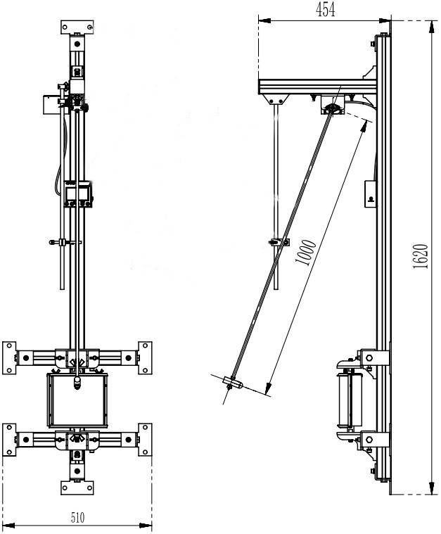
Gambar-1 1
1.2 Verifikasi Konfigurasi Peralatan
1.2.1 Membongkar
Saat membuka kemasan perangkat, tangani dengan hati-hati untuk menghindari goresan pada casing dengan alat tajam. Setelah membuka kemasan, periksa terlebih dahulu bagian luar perangkat untuk memastikan tidak ada deformasi atau penyok yang terlihat, dan tombol-tombolnya tidak rusak atau longgar. Jika Anda menemukan kelainan pada perangkat atau aksesorinya, segera hubungi kami.
1.2.2 Unit Utama dan Aksesoris
Main Unit: 1 IK01-06 Impact Element Impact Test System main unit.
Main Components (Figs. 1–2):
| Jumlah | Note |
| ① | Expansion anchors, used to mount the main unit to a vertical wall |
| ② | USB charging cable, used to charge the display |
| ③ | Spare 150g impact element; the 200g impact element is already installed on the swing arm at the factory. |
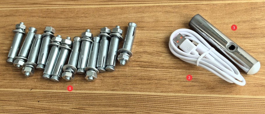
Gambar 1–2
1.2.3 Mengunduh Dokumen Elektronik
We have already sent the download links for the digital user manual, warranty card, and other documents via email at the time of shipment. Please download them as soon as possible. If you missed the email, you can contact us to request the download links again.
2. Tindakan Pencegahan Keamanan
2.1 Keselamatan Operasional
You must wear impact-resistant gloves and safety goggles to prevent flying debris or ricochets from the impact components from causing injury;
Unauthorized personnel are prohibited from entering the test area to prevent accidental injury.
2.2 Keselamatan Lingkungan
The ambient temperature should be maintained between 5°C and 35°C, with relative humidity ≤ 75%;
Leave at least 2000 mm of space in front of the equipment to ensure that the swing arm can lift properly and that there are no obstructions in the surrounding area;
When mounting the equipment on a wall, ensure it is vertical, with a tolerance of ≤0.5°.
3. Ikhtisar Peralatan
3.1 Introduction to the Host
Introduction to the Host System Components (Figure 3-1).
| Jumlah | Note |
| ① | Mounting holes, 12 in total |
| ② | Sample holder, with adjustable angle and position |
| ③ | Impact element, replaceable |
| ④ | Mengayunkan tangan |
| ⑤ | Adjustable arm mounting bracket |
| ⑥ | Fixed Device for the Impact Height of a Swing Arm |
| ⑦ | Display showing the current swing arm angle and impact height |
| ⑧ | Sensor that monitors the angle of the swing arm and automatically calculates the impact height |
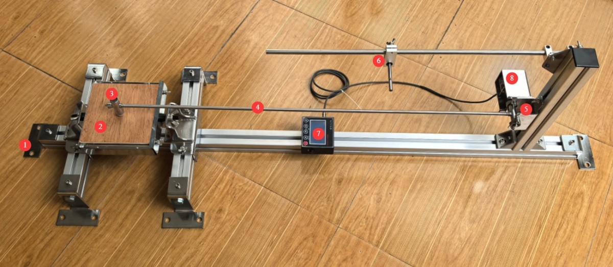
Gambar-3 1
3.2 Replacing The Impact Element
Steps for Replacing the Impact Element (Fig. 3-2).
| Jumlah | Note |
| ① | Remove the two small screws at the top and bottom |
| ② | Buka murnya |
| ③ | Unscrew the counterweight, then tap the connecting rod out. |
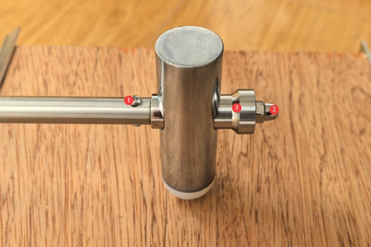
Gambar-3 2
The disassembled impact components are shown in the figure below (Figure 3-3):
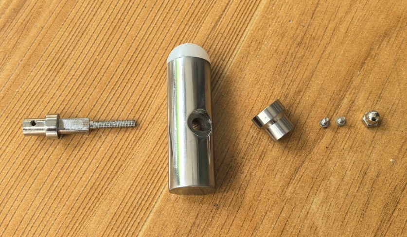
Gambar-3 3
Next, assemble the impact elements of different weights and install them onto the swing arm, paying attention to the orientation of the hammer head during installation.
3.3 Introduction to the Display
Display Introduction Features (Fig. 3-4).
| Jumlah | Note |
| ① | USB Charging Port |
| ② | Display power switch: Press and hold for 1 second to turn on; press briefly to turn off. |
| ③ | Confirm Button/Reset Button |
| ④ | The adjustment button allows you to set the length of the swing arm; the factory default setting is 1 m. |
| ⑤ | Number Up/Down keys: Increase or decrease the number when setting parameters |
| ⑥ | Battery level indicator—please recharge promptly when the battery is low. |
| ⑦ | Current Impact Height Display |
| ⑧ | Current Swing Arm Angle Display |
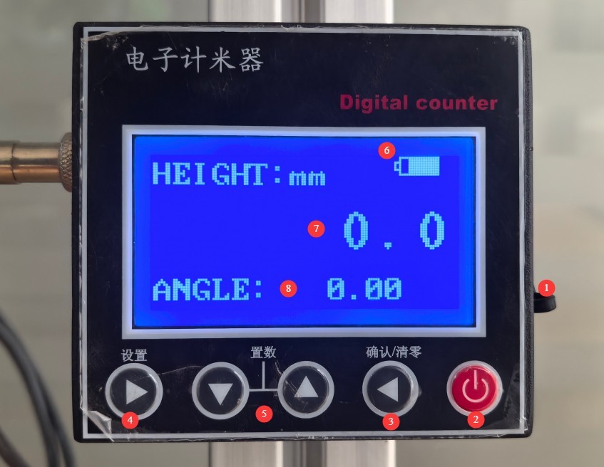
Gambar-3 4
4. Uji Dampak
4.1 Sample Mounting and Installation
4.1.1 Fiksasi Sampel
Secure the sample in the center of the plywood.
4.1.2 Position Adjustment
The position and angle of the sample holder are adjustable, and the position of the swing arm mounting device is adjustable. Adjust these so that the hammer head and the sample impact point are at the same height, and the direction of impact is perpendicular to the cross-section of the impact point.
4.2 Impact Parameter Settings
4.2.1 Set to 0 at Startup
When you turn on the display, it will show random angle and height values. Press the reset button to set the current swing arm angle and impact height to 0.
4.2.2 Adjusting the Impact Height
Raise the pendulum arm; the display will show its real-time angle and impact height. Refer to the table below to raise the pendulum arm to the desired impact height, and secure it using the pin on the height locking device. See Figure 4-1.
| Tingkat IK | IK01 | IK02 | IK03 | IK04 | IK05 | IK06 | ||||
| Energi J | 0.14 | 0.2 | (0.3) | 0.35 | (0.4) | 0.5 | 0.7 | 1 | ||
| Equivalent mass (kg) | 0.25 | (0.2) | 0.25 | (0.2) | 0.25 | (0.2) | 0.25 | |||
| Tinggi Jatuh (mm) | 56 | (100) | 80 | (150) | 140 | (200) | (250) | 200 | 280 | 400 |
Note: The values in parentheses correspond to the requirements of the previous version of the standard. If testing is to be conducted in accordance with the previous version of the standard, a 150-gram impact element must be installed.
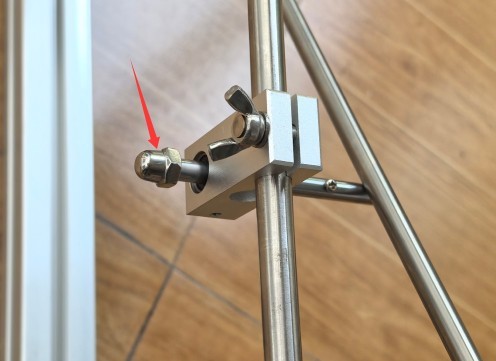
Gambar-4 1
4.2.3 IK Impact Test
Slowly pull out the pin securing the swing arm height (Fig. 4-1) to perform the impact test.
To prevent the impact element from striking repeatedly due to inertia, after the impact element has completed an impact and bounced back, you must manually hold the impact element and slowly return it to its original position. Do not use your hand to directly grip the swing arm to stop it (as this can easily cause the swing arm to deform).
Adjust the position of the sample and continue conducting impact tests on the other test points until the entire test is complete.
4.3 Post-Test Procedures
4.3.1 Equipment Shutdown and Reset
Turn off the display and allow the impact element to hang freely.
4.3.2 Sample Preparation and Observation
Visual inspection: Check the sample housing for cracks, dents, or peeling, and check whether any fasteners are loose;
Functional Testing: When the sample is powered on, test whether all functions are operating normally and ensure there are no functional failures;
Determine whether the product meets the IK rating requirements based on the product standards, and record the testing process (test points, number of impacts, etc.) and the test results (pass/fail).
5. Pemeliharaan dan Perawatan Peralatan Harian
5.1 Persiapan Lingkungan Pengujian
Clean the equipment surfaces: Wipe down the test fixture, stage, and impact elements with a dry cloth to remove dust and grease. Do not use water or corrosive cleaning agents;
Tidy up the test area: Remove any sample debris (if present), organize tools and accessories, and keep the area clean and tidy.
5.2 Long-Term Storage and Maintenance (When Not in Use for More Than 1 Month)
Component Storage: After cleaning the impact components and swing arms, apply rust-preventive oil and place them separately in packaging boxes to prevent collisions;
Maintenance of Lubricated Parts: The pin on the swing arm height lock and the pivot on the swing arm lock must both be lubricated to ensure proper lubrication;
Equipment Protection: Cover with a dust cover; store in a dry, well-ventilated environment at a temperature of 5–35°C and humidity of ≤75%;
Charge regularly: Store the device after fully charging it, and charge it once a month to run a self-test.
5.3 Persyaratan Interval Kalibrasi
Untuk memastikan akurasi pengukuran dan keandalan operasional peralatan, disarankan agar peralatan tersebut secara berkala dikirim ke laboratorium metrologi pihak ketiga yang berkualifikasi untuk kalibrasi. Interval kalibrasi yang disarankan adalah 12 bulan. Pengguna dapat menentukan interval kalibrasi spesifik berdasarkan frekuensi penggunaan, kondisi lingkungan, dan persyaratan sistem mutu.
6. Pemecahan Masalah dan Penyelesaian Masalah Umum
| Gejala Kesalahan | Kemungkinan penyebab | Prosedur |
| The display won’t turn on | Low battery on the display | Try charging it again using the standard USB cable. |
| Abnormal altitude and angle readings | Not reset to zero | Every time the display is turned on, it shows random height and angle readings, and you must press the reset button to reset them. |
7. Daftar Kemasan
| Nomor | Nama | Jumlah |
| ① | IK01-06 Impact Element Test System Main Unit (includes a 150g impact element) | Unit 1 |
| ② | Sekrup Ekspansi | 12 |
| ③ | Kabel Pengisian USB | Sepotong 1 |
| ④ | 200g shock element | 1 |