
 Inggris
 中文简体
中文简体 Русский
 Español
 Português
 Türkçe
 العربية
 Deutsch
 Polski
 Italiano
 Français
 한국어
한국어 ไทย
ไทย Tiếng Việt
 日本語
日本語





























Ballast Referensi Frekuensi Tinggi yang Dapat Disesuaikan
Pengguna manual
berlaku LISUN Model: HCS-109A
Dear Customer: Thank you for choosing the HCS-109A Adjustable High Frequency Reference Ballast. This instrument was developed by LISUN Shanghai Lishan and complies with the latest technical protocol of the UL 1993 standard. It employs a constant-current power supply method, replacing the original constant-voltage method, and serves as a 25 kHz high-frequency constant-current (electronic) reference ballast for testing Type A lamps (T8). It is used in the LED replacement lamp manufacturing industry and for Type A LED lamps (UL-certified direct replacements for fluorescent lamps) to perform input testing, temperature rise testing, leakage current testing, and harmonic distortion testing. It is a specialized instrument for non-routine testing and inspection of LED lamps and drivers. Its applications span various fields, including lamp design, process control, quality management, analytical testing, and the design of Type A LED replacement lamps. The HCS-109A LED Adjustable High Frequency Reference Ballast can also be combined with optoelectronic measurement equipment to perform various standard tests on LED lamps.
1. Panel Layout
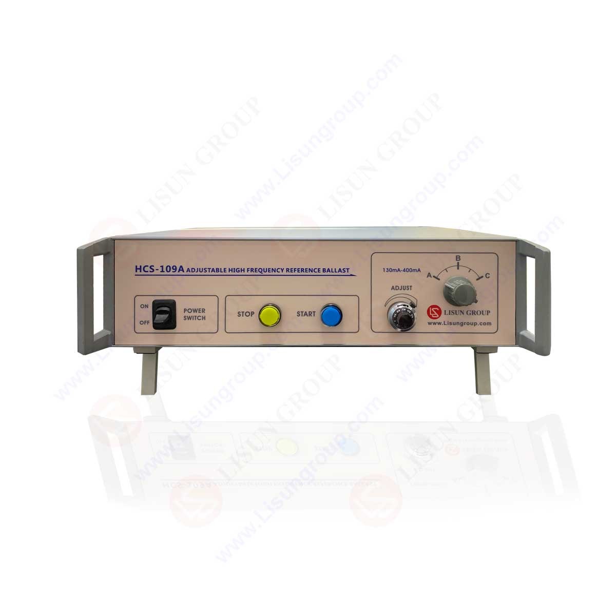
HCS-109A Adjustable High Frequency Reference Ballast Front Panel Diagram: Power Switch, Stop Button, Start Button, Indicator Light, Current Fine-Tuning Knob, Current Range Selector Switch
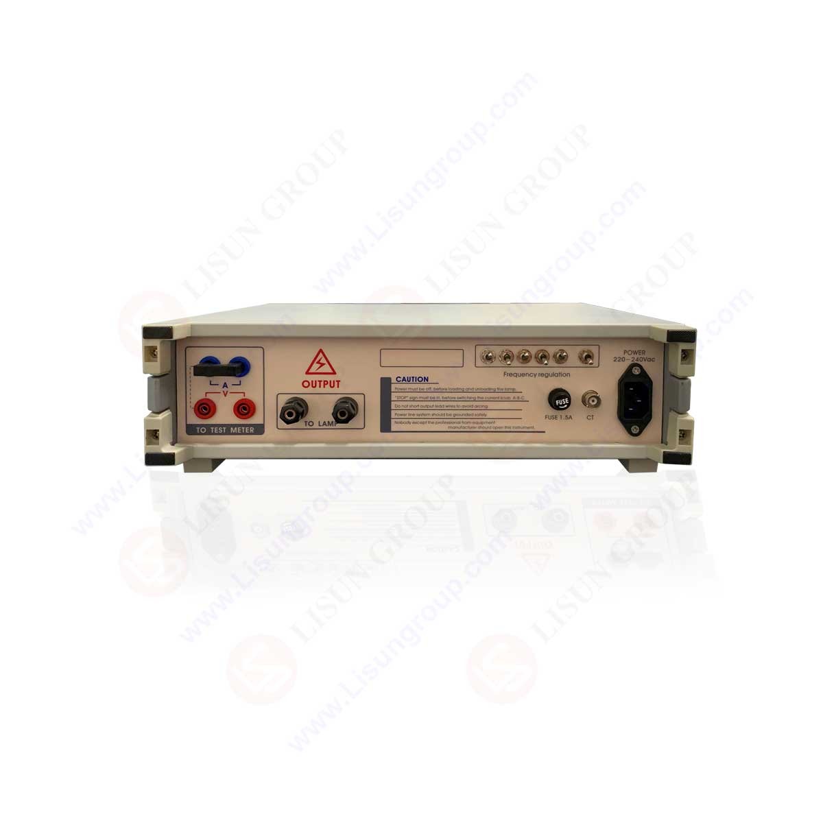
HCS-109A Power Outlet: Schematic Diagram of the Rear Panel of the Adjustable High Frequency Reference Ballast—External Meter Port, Lamp Under Test Connection, Power-Side Fuse Holder, Frequency Adjustment, and Lamp Current Detection
2. Diagram of External Instrument Connections
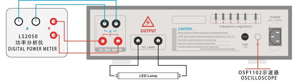
Test Setup 1: Can be used in conjunction with LISUN'S LS2050 High-Precision Digital Power Meter and OSP1102 Osiloskop Digital
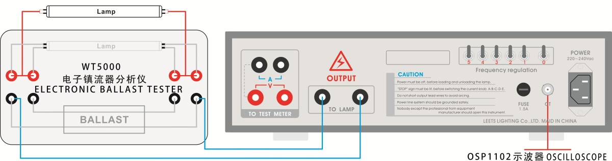
Test Setup 2: Can be used in conjunction with LISUN'S WT5000 electronic ballast tester and OSP1102 Osiloskop Digital
3. Prosedur
1. Connect the measurement system
Hubungkan HCS-109A high-frequency reference ballast to the LS2050 high-precision Digital Power Meter. Connect the output terminal (OUTPUT) of the constant-current source directly to the LED tube under test. After confirming that the tube terminals are correctly connected and make good contact, ensure that the connecting wires do not exceed 3 meters in length and check their voltage withstand ratings. Set the electrical parameter tester to the appropriate operating interface to monitor current and frequency adjustments and record the test readings.
2. Periksa catu daya
The HCS-109A is designed for use with 200 VAC to 240 VAC power supply systems. Please note that the power supply must have a ground terminal and be properly grounded.
3. Confirm the test parameters for the lamp under test
Refer to the standard documentation to determine the operating range of the lamp current for the test lamp, and set the constant-current source selector switch to the corresponding position.
4. Turn on the measurement system
Set the instrument’s power switch to ON; the STOP button on the instrument panel will light up, indicating that the instrument is in standby mode. Turn on the other external instruments connected to the system and verify that they are functioning properly. Press the START button on the panel; the test lamp should then instantly light up.
5. Measurement and Readings
After the lamp is lit, turn the ADJUST knob to adjust the lamp current to a value close to the standard specification, based on the current reading displayed by the electrical parameter meter. Use the frequency adjustment switch (0) to initially set the frequency to approximately 25 kHz, based on the frequency reading displayed by the high-frequency electrical parameter meter, then use the frequency adjustment switch (1–5) to fine-tune the frequency so that it falls within ±2% of 25 kHz. After the lit lamp has stabilized for approximately 10 minutes, repeat the above steps to perform another lamp current calibration and frequency adjustment (stabilization times vary for different lamp types and ambient temperatures). Once the rated lamp current and 25 kHz frequency have been established and the system has stabilized for a certain period, read the relevant test values for the lamp tube from the electrical parameter measuring instrument and evaluate the lamp tube’s high-frequency characteristics in accordance with standard requirements.
6. Replace the lamp and complete the measurement
After each measurement is complete, press the STOP button to stop the instrument. At this point, there will be no voltage output at the OUTPUT terminal on the rear panel, and the operator may remove the test lamp. If you need to replace the sample to continue testing, connect the sample lamp tube as described in Step 1 above. After confirming that the lamp tube ports are correctly connected and make good contact, proceed with the steps starting from Step 4. If you have finished the measurement, press the STOP button first, then turn off the instrument’s power switch.
7. Protection Against Incorrect Operation
To prevent contact arcs caused by accidental live-wire operation by the operator or poor contact with external wires, the arc protector inside the instrument will shut down the instrument (the STOP button will light up). Please ensure that the wires are securely connected before pressing the START button again to restart the instrument and begin measurement.
4. Catatan Penting
1. After each sample change, the load characteristics change, so the lamp current and operating frequency must be manually adjusted to the appropriate settings.
2. Remove the test lamp only after confirming that the power switch is turned off or the instrument has stopped operating.
3. Do not use dual-conductor cables or metal-shielded cables between the instrument and the test lamp, as this may cause fluctuations in the high-voltage output.
4. Do not shift gears until you confirm that the STOP button is lit. Do not use the gear selector to stop the machine.
5. The instrument’s power supply system should have a proper safety ground.
6. Do not short-circuit the output ports on the rear of the chassis or the wires connected to the lamp tubes. Avoid short circuits that could cause intense arcing and damage the instrument or the lamp tubes under test.
7. When selecting an electrical parameter measuring instrument, pay attention to its permissible high-frequency operating range (up to 100 kHz). Choose high-quality instruments from domestic or international manufacturers, such as the Shanghai Lishan LS2050, untuk memastikan keakuratan.
8. The equipment contains high-voltage components. Unless you are a manufacturer-authorized technician, do not open the instrument to repair it.