Inggris
 中文简体
中文简体 Русский
 Español
 Português
 Türkçe
 العربية
 Deutsch
 Polski
 Italiano
 Français
 한국어
한국어 ไทย
ไทย Tiếng Việt
 日本語
日本語





























Ruang Kelembaban Suhu Tinggi dan Rendah
Pengguna manual
berlaku LISUN models: GDJS-010A、GDJS-010B、GDJS-010C、GDJS-010D、GDJS-013A、GDJS-013B、GDJS-013C、GDJS-013D、GDJS-015A、GDJS-015AS、GDJS-015B、GDJS-015C、GDJS-015D、GDJS-020A、GDJS-020B、GDJS-020C、GDJS-020D、GDJS-030A、GDJS-030B、GDJS-030D、GDJS-100A、GDJS-100B、GDJS-100C、GDJS-100D、GDJS-225A、GDJS-225B、GDJS-225C、GDJS-225D、GDJS-500A、GDJS-500B、GDJS-500C、GDJS-500D、GDJS-800A、GDJS-800B、GDJS-800C、GDJS-800D
1. Pemahaman Dasar tentang Peralatan
1.1 Spesifikasi Teknis Utama
| LISUN Pilih Model | GDJS-100 * | GDJS-225 * | GDJS-010 * | GDJS-015 * | GDJS-020 * | |
| Working Compartment Dimensions (cm) | 41 55 × × 45 | 50 60 × × 75 | 70 80 × × 90 | 100 100 × × 100 | 100 100 × × 150 | 100 100 × × 200 |
| Dimensi Eksternal (cm) | 105 105 × × 156 | 105 102 × × 200 | 132 132 × × 217 | 167 152 × × 231 | 245 160 × × 231 | 160 254 × × 214 |
| Daya Operasi | 5.5 kW | 7.0 kW | 13.5 kW | 15.0 kW | 16.5 kW | 26.5 kW |
| Rentang Suhu | A: -20°C to 150°C B: -40°C to 150°C C: -60°C to 150°C D: -70°C to 150°C | |||||
| Variability/Uniformity | Suhu ±0.5°C/±2°C | |||||
| Rate of temperature rise | 1.0°C hingga 3.0°C per menit | |||||
| Tingkat pendinginan | 0.7°C hingga 1.0°C per menit | |||||
| kelembaban Rentang | 20% –98% RH | |||||
| Penyimpangan kelembaban | -2% hingga -3% | |||||
1.2 Membuka Kemasan dan Memeriksa Isinya
1.2.1 Membuka Kemasan dan Pemeriksaan Visual
Handle the unit with care when unpacking it. Do not use sharp tools to avoid scratching the equipment’s exterior. After unpacking, inspect the main unit first: check that the housing shows no deformation, dents, or peeling paint, and ensure that the control panel instruments and buttons are not damaged or loose. If you discover any damage to the device or its accessories, do not power it on. Contact LISUN Layanan pelanggan segera.
1.2.2 Unit Utama dan Aksesoris
1 GDJS Series High and Low Temperature Humidity Chamber.
The spare parts box is typically mounted inside the test chamber. Please open the spare parts box; standard spare parts are shown in Figure 1-1.
| Jumlah | Note |
| ① | Pipa air |
| ② | Rubber plug, used to seal the cable openings on the side of the test chamber |
| ③ | Spare heating elements: If the equipment has been in use for a long time and the heating elements inside the boiler are damaged, users can replace them themselves. |
| ④ | Spare filters; the test chamber requires regular filter replacement. |
| ⑤ | Spare fuses, spare |
| ⑥ | Backup Solid-State Relay |
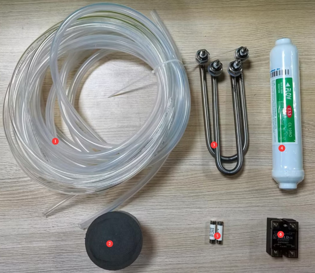
Gambar-1 1
1.2.3 Mengunduh Dokumen Elektronik
We have already sent download links for the electronic user manual, calibration certificate, warranty card, and other documents via email at the time of shipment. Please download them as soon as possible. If you have not received the email, please contact us to request the download links again.
1.3 Deskripsi Struktur Peralatan
1.3.1 Tampilan Depan Ruang Uji
Lihat Gambar 1–2.
| Jumlah | Note |
| ① | Control Panel |
| ② | The test chamber door is either a single door or a double door, depending on the size of the test chamber. |
| ③ | Condenser Vent |
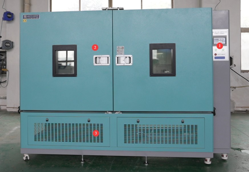
Gambar 1–2
1.3.2 Bagian Belakang Ruang Uji
Lihat Gambar 1–3.
| Jumlah | Note |
| ① | Pengukur Tekanan Refrigeran |
| ② | This is an overflow outlet; a small amount of water will flow out during the test. Simply connect this water pipe to a drain. A water pipe with an inner diameter of 10 mm is required. |
| ③ | This valve serves as a drain outlet. Open it when the equipment has not been used for an extended period or when the boiler needs to be cleaned to drain the water from inside the equipment. A water pipe with an inner diameter of 8 mm is required. |
| ④ | Water Inlet: The test chamber requires water to conduct humidity tests. Since the test chamber does not have a water pump, it must be connected to a clean water source with a pressure of at least 0.3 MPa (preferably purified water free of impurities and minerals, as otherwise the heating elements inside the boiler may burn out). Otherwise, water cannot enter the boiler, and the test chamber will be unable to perform humidity tests. The water tank can be placed in a safe location on top of the test chamber, utilizing the difference in elevation to generate water pressure. A water pipe with an outer diameter of 8 mm is required. |
| ⑤ | Kabel Listrik |
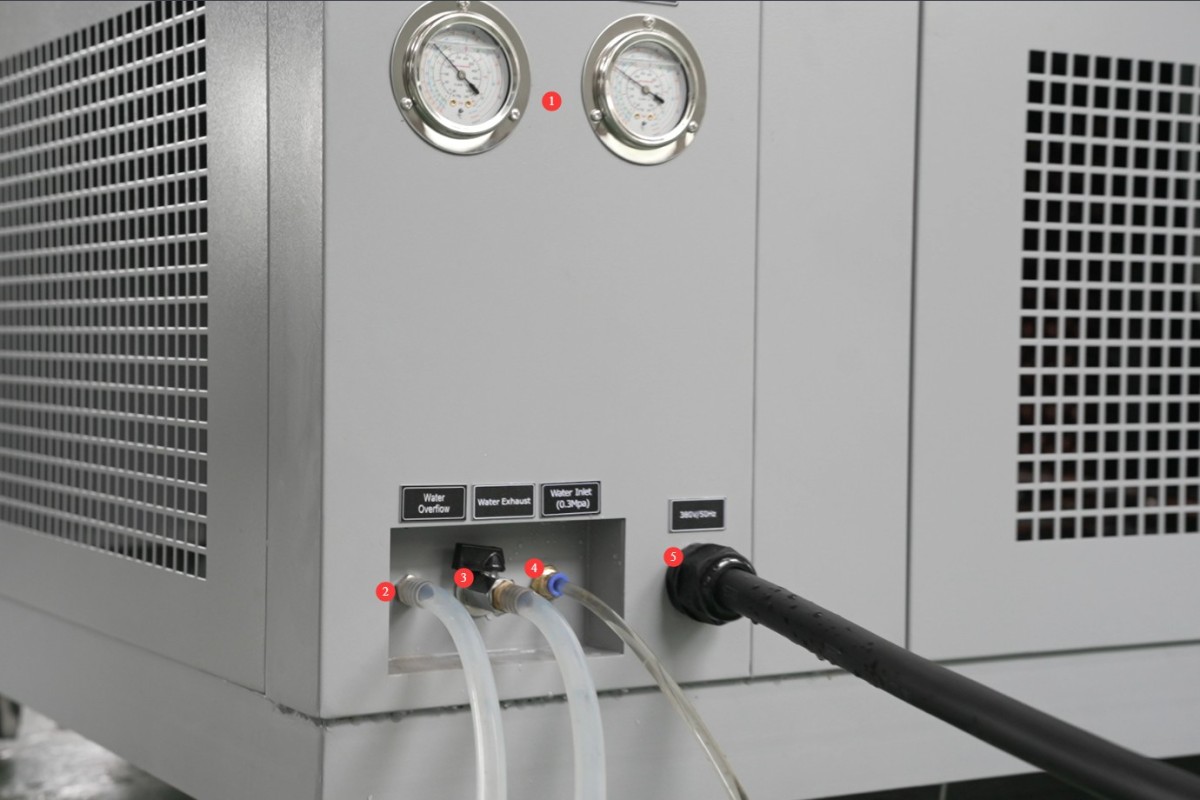
Gambar 1–3
1.3.3 Side of the Test Chamber
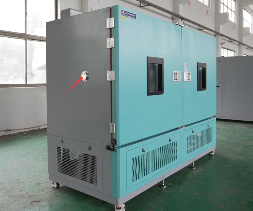
Gambar 1–4
1.3.4 Di Dalam Ruang Uji
Lihat Gambar 1–5.
| Jumlah | Note |
| ① | Digital Temperature and Humidity Gauge |
| ② | Saluran Ventilasi |
| ③ | Shelves—the number depends on the size of the test chamber; the shelf height is adjustable; samples must be placed on the shelves. |
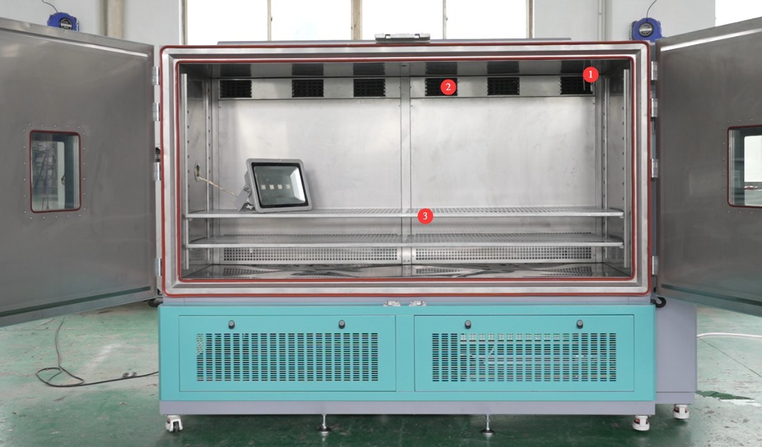
Gambar 1–5
2. Tindakan Pencegahan Keamanan
2.1 Keamanan Listrik
2.1.1 Spesifikasi Koneksi Daya
Peralatan harus dialiri daya dari sirkuit khusus dengan sistem tiga fasa, lima kawat yang bertegangan AC 380 V, 50 Hz (atau 60 Hz, opsional). Beberapa unit tidak boleh menggunakan satu sumber daya untuk mencegah penurunan tegangan yang dapat menyebabkan kinerja abnormal atau kerusakan peralatan. Sebelum menghubungkan catu daya, pastikan daya dimatikan. Saat melakukan pemasangan kabel, bedakan dengan jelas antara kabel fasa (L1, L2, L3), kabel netral (N), dan kabel ground (PE). Urutan pemasangan kabel harus sesuai dengan persyaratan skema listrik peralatan; membalik kabel fasa dan netral dilarang keras.
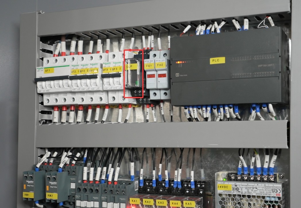
Gambar-2 1
After completing the wiring, pull firmly on the terminal blocks to ensure the connections are secure and free of looseness.
2.1.2 Persyaratan Pembumian
The equipment must be reliably grounded, with a grounding resistance of ≤4 Ω. Do not use gas pipes, non-metallic water pipes, or neutral wires as substitutes for grounding wires. After grounding is complete, use a Grounding Resistance Tester to measure the grounding resistance. Do not energize the equipment until you have confirmed that it meets the requirements, to prevent electric shock, equipment malfunctions, or measurement errors caused by poor grounding.
2.1.3 Tindakan Pencegahan Pengoperasian Listrik
Before wiring, inspecting, or maintaining the equipment, you must turn off the circuit breaker on the back of the unit and disconnect the main power supply, and confirm that there is no residual voltage before proceeding;
Jangan mengoperasikan sakelar daya peralatan, layar sentuh, atau tombol instrumen dengan tangan basah untuk menghindari risiko sengatan listrik;
Jangan meletakkan benda asing apa pun (seperti perkakas atau kertas) di dalam kabinet kontrol listrik untuk mencegah debu atau benda asing menyebabkan korsleting atau merusak komponen;
Jangan mencolokkan atau mencabut kabel daya atau kabel sinyal saat peralatan sedang beroperasi untuk mencegah korsleting yang dapat merusak pengontrol atau komponen listrik.
2.2 Keselamatan Operasional
2.2.1 Persyaratan Spesimen Uji
The equipment must not be used for testing flammable, explosive, toxic, or highly corrosive substances (such as alcohol, gasoline, strong acids, strong bases, etc.). The equipment is not equipped with explosion-proof devices, and such substances may cause fires, explosions, or corrosion of the equipment;
If the test specimen generates heat (such as during powered testing of electronic components), an external, independent power source must be provided for the specimen. Do not use the equipment’s own power supply directly to avoid overloading the equipment’s circuitry;
The sample volume must not exceed 80% of the test chamber’s capacity, and the weight must not exceed the specified load capacity of the shelves (30 kilograms per shelf) to prevent deformation of the shelves or disruption of the temperature and humidity cycling.
2.2.2 Keselamatan Operasional
Non-professionals are prohibited from disassembling or repairing the equipment while it is in operation. In the event of a malfunction, contact LISUN Customer Service or follow the instructions of a technician.
Avoid opening the chamber door as much as possible when temperatures are high (≥80°C) or low (≤-20°C): Opening the door may cause burns or frostbite and disrupt the temperature and humidity balance (affecting test results).
If you must open the door, wear heat-resistant gloves and safety goggles, open the door slowly, and wait until the internal temperature and humidity have stabilized before proceeding.
Do not set the temperature or humidity above the device’s operating range; doing so may burn out the heating element or damage the cooling system.
If the equipment triggers an alarm, stop the test immediately and troubleshoot the problem (see Chapter 7). Do not force the equipment to restart (to prevent further damage).
2.2.3 Perilaku yang Dilarang
Do not open the control cabinet door while the equipment is running to avoid touching the high-voltage components inside and causing an electric shock;
Do not disassemble core components such as the temperature sensor (PT100 platinum resistance thermometer), heating element, or condenser without authorization. Modifying the equipment will void the warranty and may result in safety incidents;
Do not place heavy objects (such as tools or accessories) on top of the device to avoid damaging the device panel or impairing heat dissipation;
Do not pile flammable items (such as cardboard boxes, plastic wrap, etc.) around the equipment; keep the equipment’s ventilation openings clear to prevent the risk of fire.
2.3 Keselamatan Lingkungan
2.3.1 Persyaratan Instalasi
The equipment must be installed in an air-conditioned room, with the ambient temperature maintained between 5°C and 25°C and relative humidity ≤85%. If the ambient humidity is high, condensation may form near the equipment door and test ports; in such cases, improve room ventilation or use a dehumidifier;
Lokasi pemasangan harus bebas dari konsentrasi debu yang tinggi, gas korosif (seperti sulfur dioksida dan klorin), dan atmosfer yang mudah terbakar atau meledak. Sinar matahari langsung tidak boleh mengenai peralatan untuk mencegah korosi pada wadah peralatan dan kerusakan komponen listrik;
Keep the device away from areas with significant fluctuations in ambient temperature, such as near vents or room entrances, to prevent the device’s temperature control accuracy from being affected.
2.3.2 Persyaratan Ruang
The distance between the equipment enclosure and the wall, as well as surrounding structures (such as other test equipment and shelves), must be at least 1500 mm to ensure unobstructed ventilation at the equipment’s heat dissipation openings (rear and sides);
At least 2000 mm of space must be left at the equipment door to ensure that the door can be opened in any direction, facilitating the placement and removal of samples;
2.3.3 Penempatan Horizontal
The equipment must be placed on a level surface. Use a spirit level to ensure the equipment is level: Place the spirit level on the top surface of the equipment and confirm that the bubble is centered. Note: The following types of legs are adjustable to ensure the test chamber is level; see Figure 2-2:
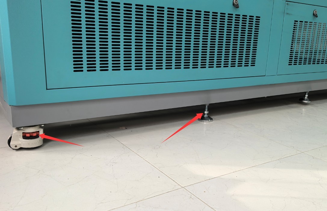
Gambar-2 2
If the equipment is tilted, it may compromise the structural stability of the test chamber, affect the liquid levels in all internal water containers, cause uneven distribution of temperature and humidity within the chamber, and even result in an uneven chamber door that does not seal properly, thereby affecting test results and the equipment’s service life.
2.4 Lainnya
Untuk hal-hal yang tidak tercakup dalam panduan ini, harap berhati-hati atau hubungi kami.
3. Persiapan Sebelum Ujian
3.1 Connecting Water Pipes and Power Cables
See sections 1.3.2 and 2.1.
3.2 Contoh Penempatan
For sample restrictions, see Section 2.2.1. For sample placement, see Sections 1.3.3 and 1.3.4.
Note: If the sample requires the use of a cable, please reseal the side-opening channel on the outside of the test chamber using a rubber plug, as shown in Figure 3-1:
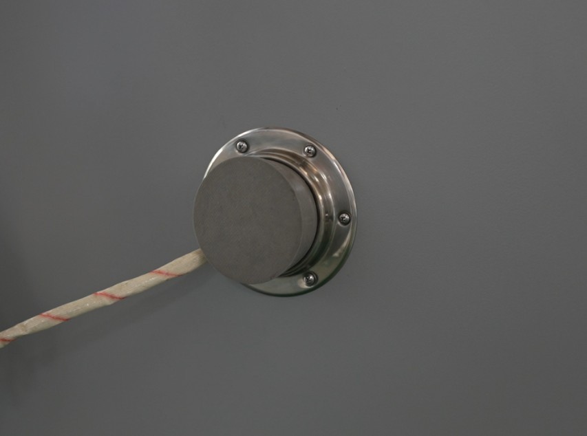
Gambar-3 1
Samples must not come into contact with the inner walls of the test chamber; do not touch or cover the temperature and humidity probes; and do not block the air ducts. Samples must be securely fastened and must not move during the test.
3.3 Menutup Pintu Kabinet
Make sure the box door is closed and the lock is secured. For double doors, first press and lock the left door, then press and lock the right door.
3.4 Starting Up the Test Chamber
3.4.1 Turn on the power to the test chamber
Press the “Power” button on the control panel on the front of the device. The touchscreen program will enter the standby screen. Ensure that there are no alarms in the program; if there are any, refer to Chapter 7 for troubleshooting.
3.4.2 Humidity System Ready
After startup, the inlet water solenoid valve opens automatically, and water is automatically fed into the boiler. You must wait until the boiler is sufficiently filled with water to completely submerge the humidification tube before performing a humidity test. If you only need to perform a temperature test and do not need to perform a humidity test, you may skip this step.
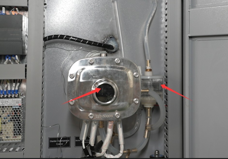
Gambar-3 2
During the humidity test, the water in the boiler is gradually consumed, and the water inlet solenoid valve automatically opens to replenish the boiler with purified water.
4. Touchscreen Program Operation Of The High And Low Temperature Humidity Chamber
4.1 Introduction to the Main Screen
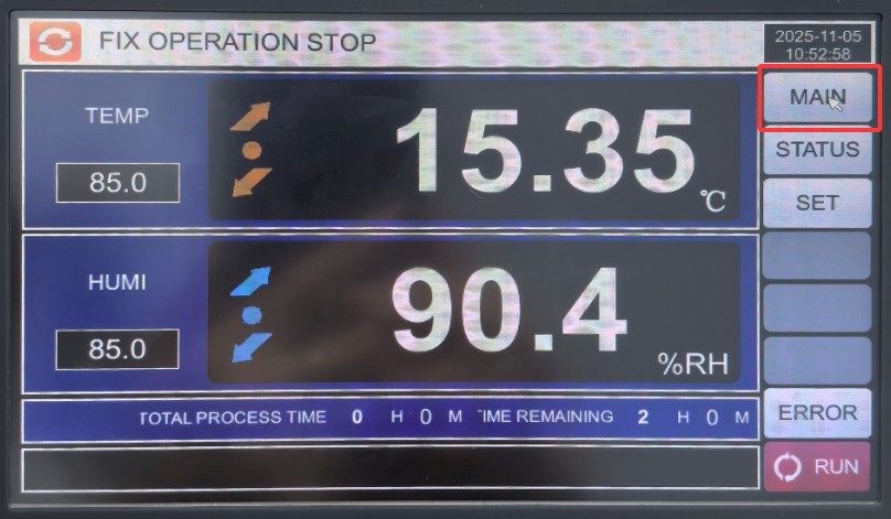
Gambar-4 1
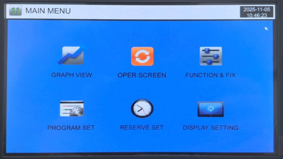
Gambar-4 2
4.2 Pengaturan Operasi
Go to the “Operation Settings” screen, as shown in Figure 4-3.
| Jumlah | Note |
| ① | Select the test operation mode: FIX (fixed values) or PRO (program) |
| ② | Once the test is complete, no action will be taken or the system will return to room temperature. If you want the system to automatically return to room temperature, please set the room temperature range. |
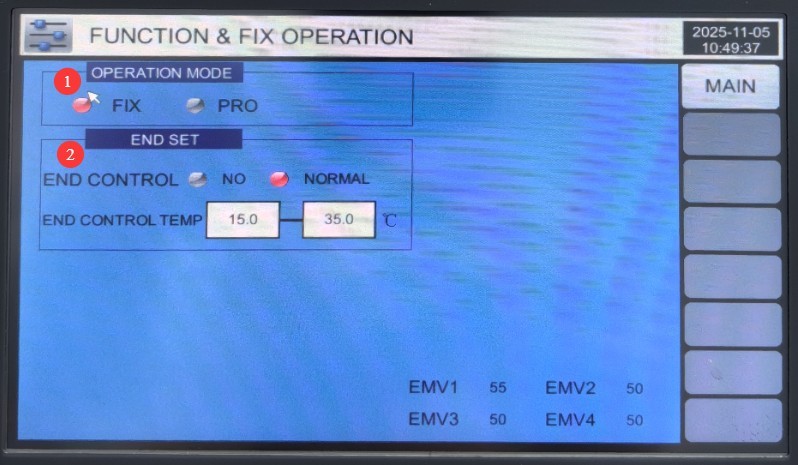
Gambar-4 3
4.3 Pengaturan Janji Temu
Go to the “Scheduled Settings” screen, as shown in Figure 4-4. The left column displays the current time, and the right column allows you to enter the scheduled time. Then, press the “RESERVE” button on the right until it turns red to confirm the schedule. The test chamber will then automatically begin the impact test at the scheduled time.
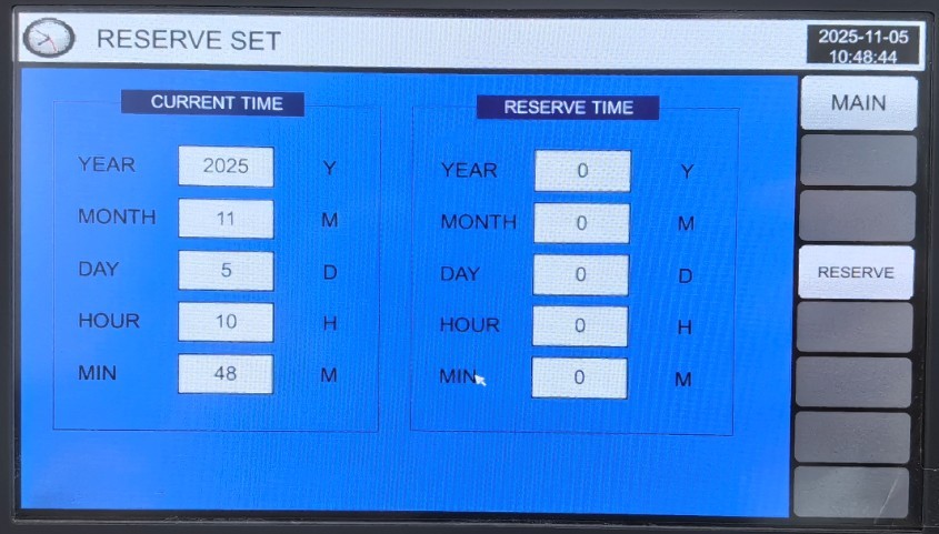
Gambar-4 4
4.4 Pengaturan Tampilan
Go to the “Display Settings” screen, as shown in Figures 4-5.
| Jumlah | Note |
| ① | Select Display Language |
| ② | Restart Methods Following an Unexpected Power Outage (Stop: An operation that restores the system to a “stop” state when power is restored after a power outage during operation; Cold Start: An operation that restarts the system from the first section when power is restored after a power outage during operation; Hot Start: An operation in which, following a power outage during operation, operation continues from the section where it was interrupted prior to the outage, restoring the system to its pre-outage state when power is restored) |
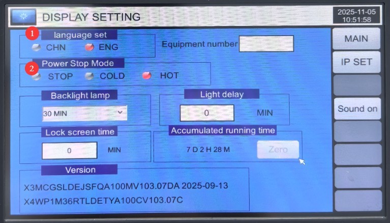
Gambar 4–5
4.5 Fixed-Value Operation (Single Temperature and Humidity Point Test)
4.5.1 Accessing the Fixed-Value Settings
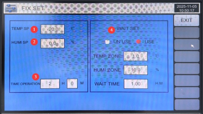
Select “Fixed Value” in “Operation Settings.” Go to the “Monitoring Screen,” then click the “Settings” button on the right to access the “Fixed Value Settings” screen, as shown in Figure 4-6.
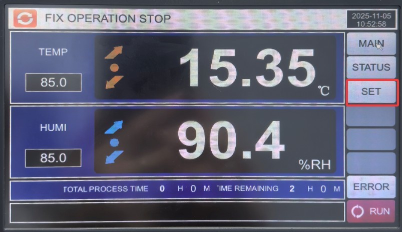
Gambar 4–6
4.5.2 Pengaturan Parameter
Lihat Gambar 4–7.
| Jumlah | Note |
| ① Temperature Setting | Enter the target temperature (see Section 1.1 for the configurable temperature range) |
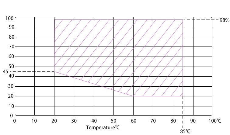
| ② Humidity Setting | Enter the target humidity (e.g., 60% RH); the range is 20%–98% RH. Conventional High and Low Temperature Chambers allow you to set the humidity range and the corresponding temperature range; see Figure 4-8. |
| ③ Scheduled Operations | Enter the test duration (e.g., 2H; range: 0–9999H); if set to 0, the test must be stopped manually. |
| ④ Wait for the settings to take effect | If the “wait” function is selected, the test chamber will not begin counting the test time until it reaches the set temperature and humidity. You must also set the tolerance range (the test is considered complete if the values fall within this range) and the wait time (if the test chamber has not reached the set temperature and humidity by the end of the wait time, it will automatically begin counting the test time). |
Gambar 4-7
Gambar-4 8
4.5.3 Starting the Calibration Test
After verifying that the parameters are correct, return to the monitoring screen and click the “Run” button in the lower-right corner.
Note: If you have set both temperature and humidity, the test chamber will first adjust the temperature to the target value; once the temperature reaches the target value, the humidity function will begin to operate. Until the temperature stabilizes, the humidity function will not operate and will remain unstable.
4.6 Test Procedure (High- and Low-Temperature and Humidity Cycling Test)
4.6.1 Program Group Settings Screen
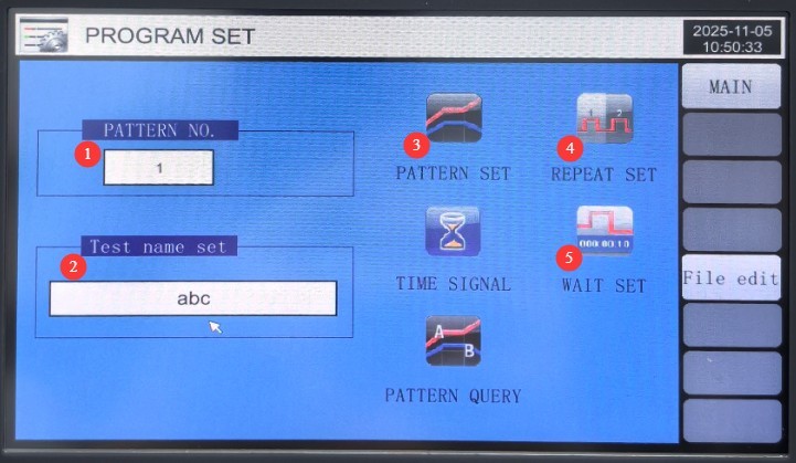
Lihat Gambar 4–9.
| Jumlah | Note |
| ① | Program number: You can set up to 100 programs, numbered 1 through 100, to avoid duplicating existing programs. |
| ② | Enter the name of this program |
| ③ | Pengeditan Program |
| ④ | Pengaturan Perulangan |
| ⑤ | Menunggu konfigurasi |
Gambar-4 9
4.6.2 Accessing the Program Editing Screen
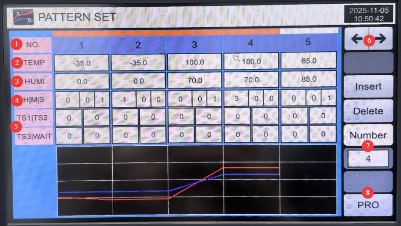
Lihat Gambar 4-10.
| Jumlah | Note |
| ① | Test segment number; each program can be set to have up to 99 test segments |
| ② | Pengaturan Suhu |
| ③ | Pengaturan Kelembapan |
| ④ | Test Duration Settings |
| ⑤ | The relay operates automatically; no parameter changes are required here. |
| ⑥ | Toggle Section Numbering |
| ⑦ | Enter the number of sections you want to run. For example, if you only want to run the first four sections, enter 4. Please enter the correct number; otherwise, the program will encounter an error. |
| ⑧ | Return to the Program Group Settings Screen |
Gambar-4 10
Example: If you need to perform the following test: Step
1: Temperature -20°, no humidity, test duration 3 hours;
Step 2: Temperature 50°, humidity 50%, test duration 5 hours. The
settings should be:
| NO. | 01 | 02 | 03 | 04 | 05 ... |
| Suhu | -20 ° | 50 ° | 0 | ||
| Kelembaban | 0 | 50 | |||
| Waktu | 0.01.00 | 3.00.00 | 0.01.00 | 5.00.00 | |
NO 01: Transition phase, i.e., the time required to reach the target temperature.
NO 02: Actual test duration: 3 hours.
NO 03: Transition phase—the time required to reach the target temperature and humidity.
NO 04: Actual test duration—5 hours.
In other words, for each set of temperature and humidity conditions, two phases must be configured: the first is the transition phase, during which the test chamber reaches the set temperature and humidity; the second is the test duration at those conditions.
Note: In the examples above, the transition phase is set to only 1 minute. The equipment has a wait function; even if the set time is short, the equipment will reach the set values before proceeding to the next phase. This configuration minimizes the equipment’s preparation time to save on test time.
4.6.3 Loop Settings Screen
Lihat Gambar 4-11.
| Jumlah | Note |
| ① | The number of times the program loops; the default value is 1, meaning the program stops immediately after the current test is completed. |
| ② | Link program number: After the current program’s test is complete, the system will automatically proceed to the next program to continue testing. If this is not desired, enter 0. |
| ③ | In the current program’s test segment loop mode, the default value for all parameters is 0, meaning the test segments are not repeated; instead, the program tests the segments sequentially from the first to the last. |
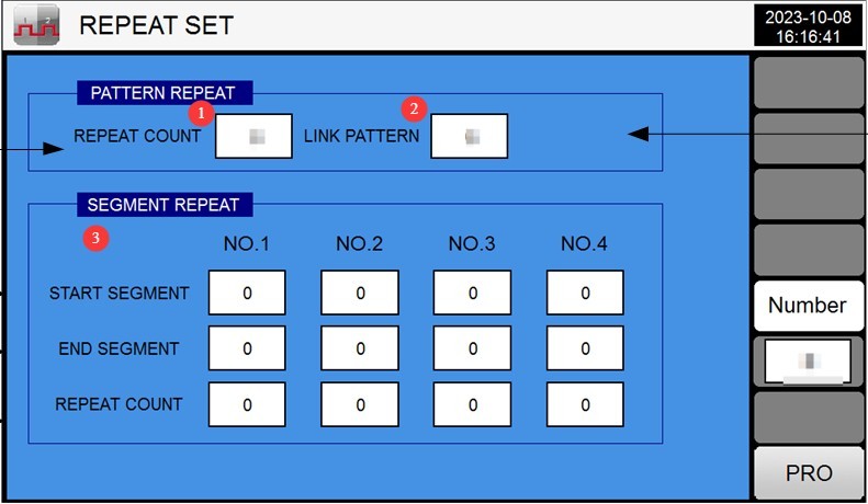
Gambar-4 11
Example: Figure 4-12 means that after the current program has been run twice, it automatically proceeds to Test Program 3 to continue testing.
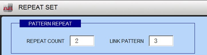
Gambar-4 12
Figure 4-13 illustrates that the current test sequence for the program is 01>02>03>04>05>03>04>05>02>03>04>02>03>04>05>06>07…
meaning testing begins with the first segment.sections 3 through 5 are repeated twice, followed by sections 2 through 4 being repeated twice, and then the remaining test segments are completed in sequence.
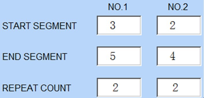
Gambar-4 13
Based on the logic above, you can configure the program’s test parameters to meet your specific testing requirements.
4.6.4 Wait for the Settings Screen
Lihat Gambar 4-14.
① Select “ALL” to enable the wait function for all test segments; ② Error tolerance for temperature and humidity wait zones; ③ Maximum wait time.
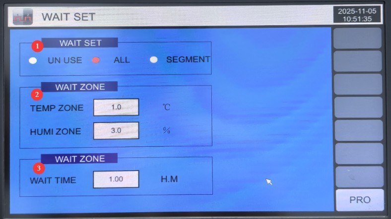
Gambar-4 14
4.6.5 Uji Startup
After verifying that the parameters are correct, return to the monitoring screen and click the “Run” button in the lower-right corner.
4.7 Test Operation and Monitoring
4.7.1 Monitoring Screen
The monitor screen displays the set temperature and humidity values, as well as the current actual temperature and humidity.
4.7.2 Pemantauan Kesalahan Secara Real-Time
If a fault occurs, the touchscreen automatically switches to the “Real-Time Fault Display Screen.”
Check the error codes and refer to Chapter 7 for troubleshooting and resolution; click “Mute” to turn off the buzzer, and click “Reset Errors” after troubleshooting is complete.
4.7.3 Viewing and Exporting Curves
Tap the “Curve Display” screen on the main screen to view real-time temperature and humidity curves (temperature: red; humidity: blue).
Insert the USB flash drive, click “Download,” and the curve data will be saved to the USB flash drive in CSV format (which can be opened and analyzed on a computer).
Tap “Clear History” (press and hold for 5 seconds) to delete old curve data (use with caution).
5. Prosedur Pasca-Ujian
5.1 Equipment Shutdown Procedures
5.1.1 Program Termination
If the program ends normally: The device operates according to the “Program End Mode,” such as “Return to Room Temperature.”
To stop the process early: Click the “Stop” button on the monitoring screen, and the device will enter standby mode.
5.1.2 Prosedur Mematikan Daya
Verify that the device is in standby mode (not running), then turn off the power switch on the device’s control panel.
Matikan saklar daya utama.
5.2 Pengambilan dan Penanganan Sampel
Wear heat-resistant gloves (as the sample may still be hot or cold even after returning to room temperature), open the chamber door, and slowly remove the sample.
Inspect the condition of the samples (e.g., appearance, performance) and record test data (temperature, humidity, time, changes in the samples).
If there is any liquid remaining on the sample, wipe it clean with a lint-free cloth to prevent contamination of the work area.
5.3 Pembersihan Peralatan
Cleaning the Inner Chamber: Wipe the inner walls and shelves of the chamber with a lint-free cloth dampened with alcohol to remove any residual sample stains (do not spray water or alcohol directly onto the surface).
Cleaning the Refrigerator Door: Wipe down the door gasket (to remove dust) and check that it is not deformed (if there are stains, wipe them off with a damp cloth).
Cleaning the Exterior: Wipe down the equipment casing with a dry cloth to remove surface dust (do not use gasoline or organic solvents, as this may cause the paint to peel).
Cleaning the Touchscreen: Wipe with a dry cloth to remove fingerprints and ensure touch sensitivity.
5.4 Catatan Tes
Fill out the equipment usage log, recording the following information: test date, program group, sample name, runtime, fault details (if any), and operator.
Organize test data (such as graphs and sample reports) and file them for safekeeping.
6. Pemeliharaan dan Perawatan Peralatan Harian
6.1 Routine Cleaning and Maintenance (Before and After Each Test)
| Proyek Pemeliharaan | Prosedur pemeliharaan | Penting Catatan |
| Inner Chamber of the Chamber | Wipe with an alcohol-soaked lint-free cloth to remove stains | Do not wash with water; avoid exposing electrical components to moisture. |
| Strip penyegelan | Wipe with a dry cloth and check for any deformation or damage. | If the rubber seal is worn out (and no longer seals properly), contact customer service to have it replaced. |
| Touchscreen | Wipe with a dry cloth to remove fingerprints and dust | Do not scratch the screen with sharp objects. |
| Vent (Air-Cooled) | Wipe off surface dust with a dry cloth and ensure proper ventilation. | Do not block the ventilation openings (to prevent overheating) |
6.2 Regular Inspection and Maintenance (Performed on a Scheduled Basis)
| Proyek Pemeliharaan | Siklus Pemeliharaan | Instruksi Perawatan | Tujuan dan Persyaratan |
| Sistem perpipaan | Setiap 2 bulan | 1. Clean the water filter cartridge; 2. Drain the water tank and rinse it out | The water lines are clear of blockages, and there are no leaks at the connections. |
| Sensor Suhu dan Kelembaban | Bulanan | Use a soft-bristled brush to remove dust from the sensor surface | Measurement accuracy within ±2°C/±3% RH |
| Condenser (Air-Cooled) | Setiap 3 bulan | Use compressed air (0.2 MPa) to blow dust off the condenser | Good heat dissipation, with no decrease in cooling efficiency |
| Resistensi Tanah | Grounding Resistance Tester Inspection | Resistansi tanah ≤ 50 Ω | |
| Komponen listrik | Setiap 6 bulan | Open the control cabinet door and check that the relays and terminal blocks are secure. | No oxidation or loose connections; the circuit breaker is functioning normally. |
6.3 Long-Term Downtime for Maintenance (More Than 1 Month)
6.3.1 Preparations Before Shutdown
Complete the final cleaning (inner tank, outer casing, and ventilation openings) to ensure no stains remain.
Drain the water from the tank and water lines (to prevent freezing and expansion from damaging components).
6.3.2 Power Outage and Protection
Turn off all power sources (device power switches, main power supply), disconnect power cords and water lines, and organize the cables (to prevent them from being pinched).
Cover the equipment with a plastic dust cover and store it in a dry room (temperature 5–25°C, humidity ≤ 60%).
6.3.3 Inspeksi Berkala
Every 15 days, open the dust cover, ventilate for 30 minutes, and check the inner liner for moisture (if there is any moisture, wipe it off with a dry cloth).
Start the equipment once a month, set it to 50°C, and run it for 30 minutes (no load) to dry out any internal moisture and extend the life of the components.
7. Pemecahan Masalah dan Penyelesaian Masalah Umum
7.1 On-Screen Error Codes and Troubleshooting
| Kode Masalah | Kemungkinan penyebab | Solusi |
| Kompresor X2 No. 1 Arus Lebih | 1. Thermal overload protection has tripped; 2. Excess refrigerant | 1. Press the white reset button on the thermal overload protector; 2. Use a multifunction gauge to check the pressure in the low-pressure line; if the pressure is too high, release some refrigerant. |
| X3 Compressor #1 Overpressure | 1. Poor condenser cooling; 2. Excess refrigerant; 3. Water-cooled unit is not turned on | 1. Air-cooled: Clean dust from the condenser; Water-cooled: Turn on the water-cooling unit; 2. Check the refrigerant pressure and release any excess refrigerant |
| X10 Test Chamber Over-Temperature | 1. Over-temperature protection triggered; 2. Set temperature exceeds the upper limit; 3. Dry burning of the heating element | 1. Reset the over-temperature protection dial by turning it; 2. Reset the temperature; 3. Check the water lines to ensure the humidification system is supplying water properly |
| PT1 Temperature Probe Failure | 1. Loose PT100 sensor wiring; 2. Sensor failure | 1. Open the control cabinet door, check the PT1 wiring, and secure it again; 2. Use a multimeter to measure the sensor resistance (approximately 100 Ω at room temperature); replace it if the reading is abnormal. |
| PT2 Humidity Sensor Malfunction | 1. Loose connection in the humidity sensor; 2. Sensor damaged by moisture | 1. Check the PT2 wiring and secure it properly; 2. Replace the humidity sensor and ensure there are no obstructions at the installation site. |
7.2 Controller-Related Failures
| Gejala Kesalahan | Kemungkinan penyebab | Solusi |
| Pengontrol tersebut tidak memiliki tampilan digital. | 1. The power cord is not plugged in properly; 2. A phase is missing in the three-phase power supply; 3. Controller malfunction | 1. Check the power cord and circuit breaker to ensure power is connected; 2. Use a multimeter to measure the three-phase voltages (all around 380V); 3. Contact customer service to have the controller replaced. |
| Angka-angka pada tampilan pengontrol berfluktuasi secara tidak menentu. | 1. Loose sensor connections; 2. Significant power supply interference; 3. Controller malfunction | 1. Unplug and replug the sensor cable; 2. Move the device away from high-power equipment, or install a power filter; 3. Contact customer service for repair. |
| Kesalahan Komunikasi PLC (Menampilkan “PLC tidak merespons”) | 1. The communication cable between the controller and the PLC is loose; 2. The PLC power supply is malfunctioning | 1. Check the communication cable (RS485), and either secure it or replace it; 2. Check the PLC power supply (24V DC); if there is an abnormality, repair the power supply module. |
7.3 Heating/Cooling/Humidification Malfunctions
| Gejala Kesalahan | Kemungkinan penyebab | Solusi |
| Tanpa pemanas | 1. Over-temperature protection tripped; 2. Solid-state relay failure; 3. Heating element failure | 1. Reset the over-temperature protection; 2. Use a multimeter to measure the output terminals of the solid-state relay (replace if there is no voltage); 3. Measure the resistance of the heating element (several tens of ohms at room temperature; replace if the resistance is infinite). |
| Pemanasan Berkelanjutan (Kenaikan Suhu Terus Menerus) | 1. Stuck solid-state relay; 2. Sensor short circuit; 3. Controller malfunction | 1. Immediately turn off the power and replace the solid-state relay; 2. Inspect the sensor (replace it if there is a short circuit); 3. Contact customer service to have the controller repaired. |
| Tidak mendinginkan | 1. The cooling switch is not turned on; 2. The compressor has not started; 3. There is a refrigerant leak | 1. Go to “Operation Settings” and turn on the cooling switch; 2. Check the compressor power supply and phase sequence, then wait 3 to 5 minutes before restarting; 3. Contact customer service to locate the leak and recharge the refrigerant |
| Pendinginan lambat | 1. Low refrigerant level; 2. Clogged condenser; 3. Excess moisture in the chamber | 1. Top off the refrigerant (to the amount specified for the equipment); 2. Clean dust from the condenser; 3. Dry the moisture from the chamber before lowering the temperature |
| No humidification | 1. Low water level in the tank; 2. Humidifier malfunction; 3. Water level controller failure | 1. Check the tap water supply and ensure the water level in the tank meets the required standard; 2. Measure the resistance of the humidifier (replace if abnormal); 3. Replace the water level controller |
7.4 Masalah Umum Lainnya
| Gejala Kesalahan | Kemungkinan penyebab | Solusi |
| Kasus ini sedang berlangsung. | 1. Poor grounding; 2. Live wire touching the chassis; 3. Electrical leakage from the heater | 1. Re-ground the unit and ensure the resistance is ≤50 Ω; 2. Inspect the internal wiring and secure the live wire terminals; 3. Measure the heater’s insulation resistance; replace it if it is defective. |
| Poor door seal (temperature and humidity leakage) | 1. The weatherstripping has deteriorated; 2. The cabinet door hinges are loose; 3. The door lock is improperly adjusted | 1. Replace the weatherstripping; 2. Adjust the hinge bolts to ensure the door is vertical; 3. Turn the door lock knob to tighten the cabinet door |
| The circulation fan is not running | 1. Fan power supply failure; 2. Motor failure | 1. Check the fan wiring to ensure it is powered; 2. Use a multimeter to test the motor windings (if there is no open circuit, replace the motor) |
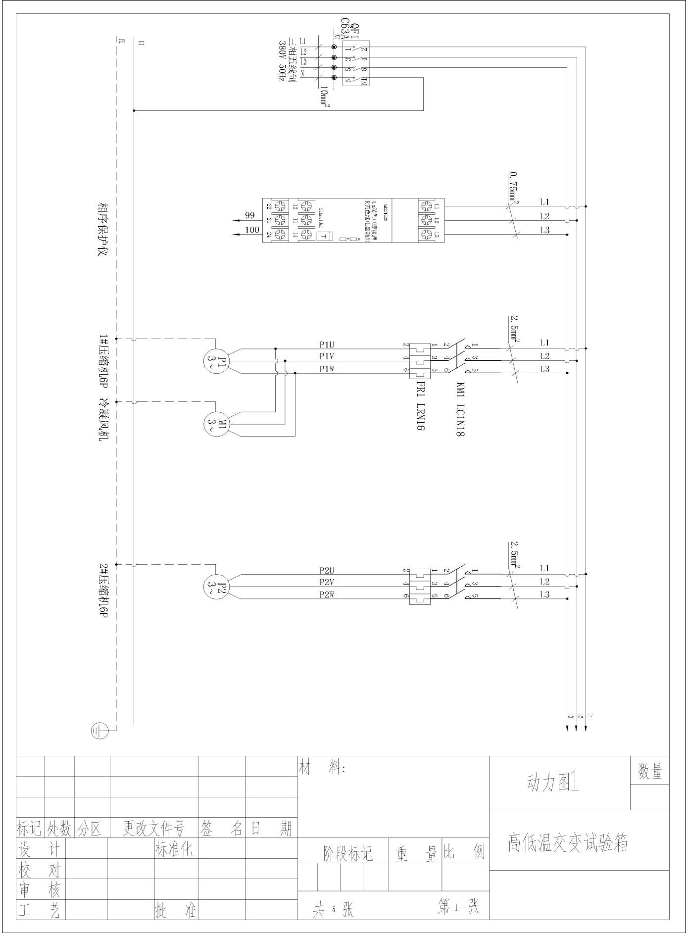
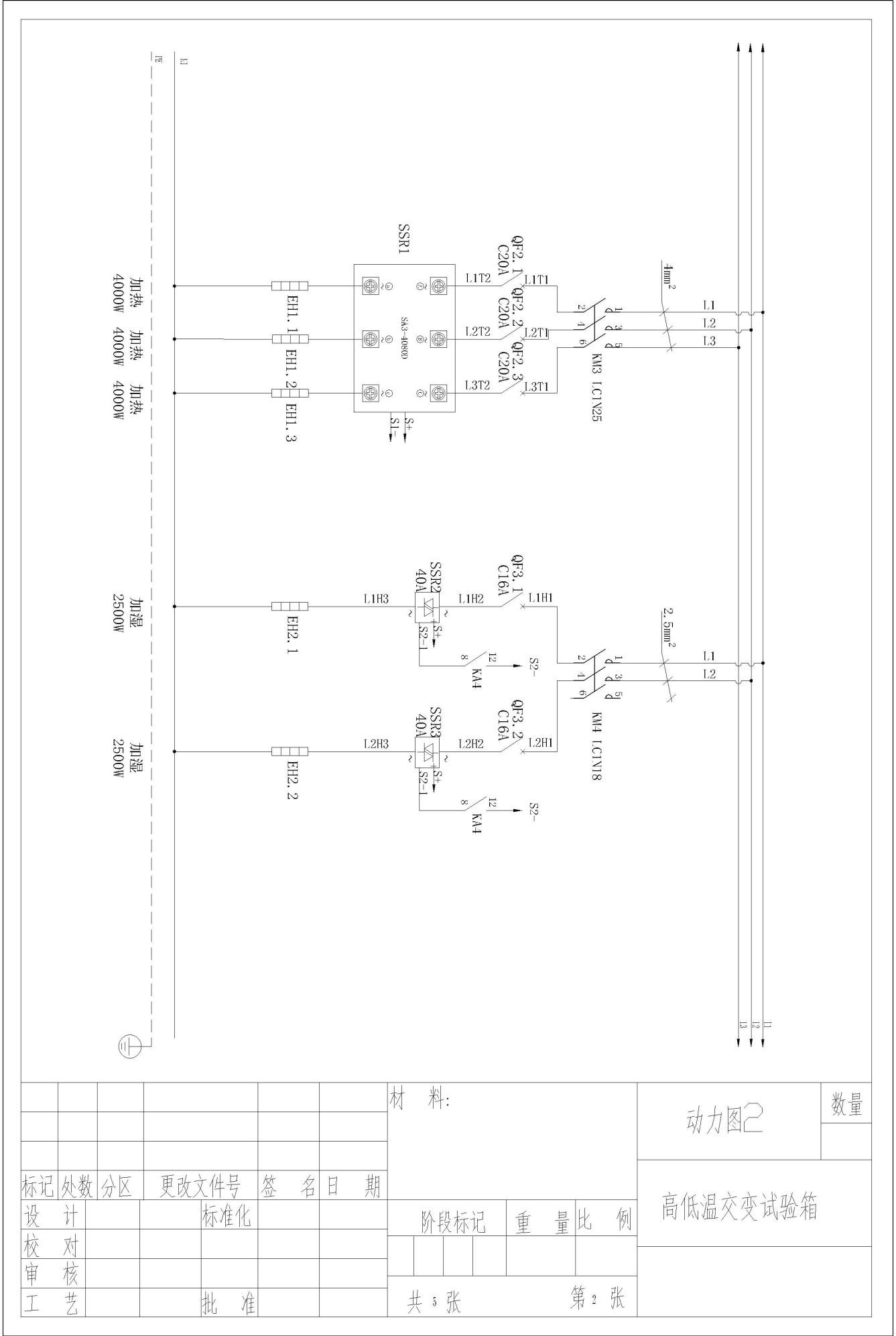
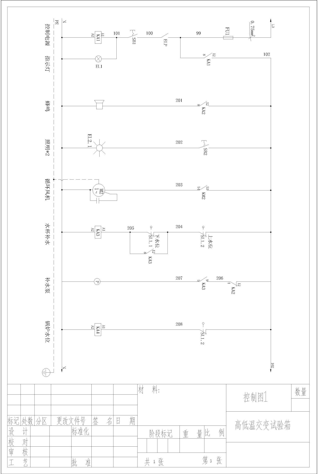
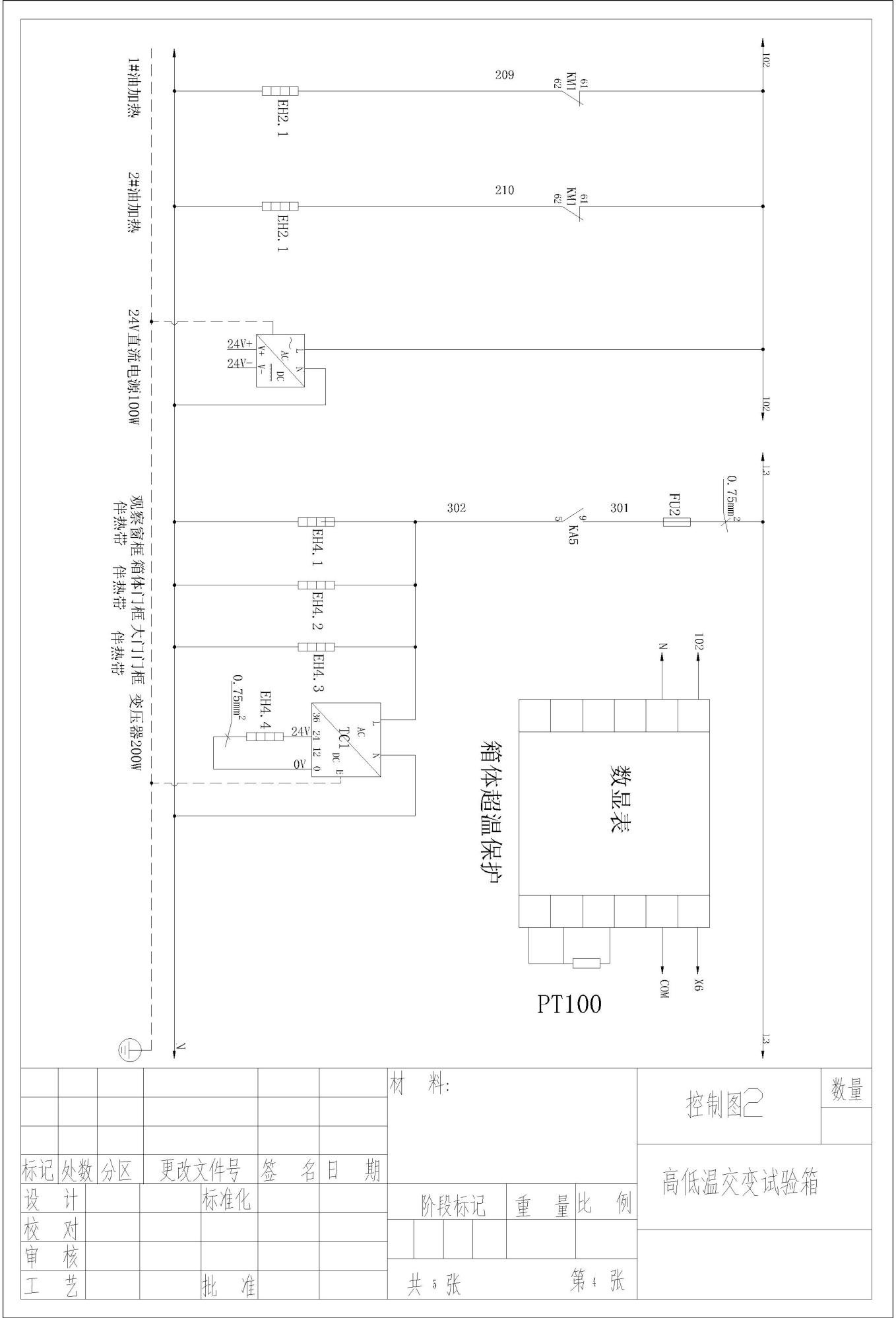
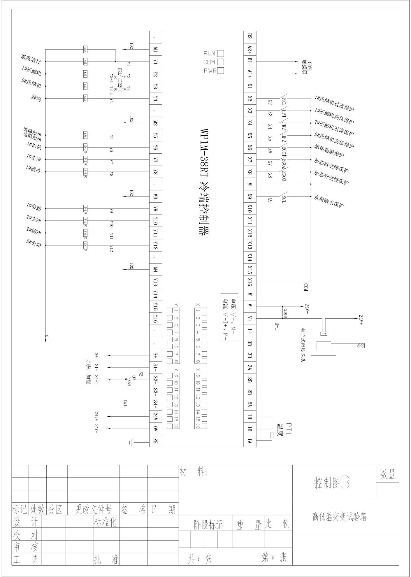
Lampiran: Diagram Rangkaian