Inggris
 中文简体
中文简体 Русский
 Español
 Português
 Türkçe
 العربية
 Deutsch
 Polski
 Italiano
 Français
 한국어
한국어 ไทย
ไทย Tiếng Việt
 日本語
日本語





























Ruang Suhu Tinggi dan Rendah
Pengguna manual
berlaku LISUN models: GDJW-013A、GDJW-013B、GDJW-013C、GDJW-013D、GDJW-015A、GDJW-015B、GDJW-015C、GDJW-015D、GDJW-020A、GDJW-020B、GDJW-020C、GDJW-020D、GDJW-100A、GDJW-100B、GDJW-100C、GDJW-100D、GDJW-225A、GDJW-225B、GDJW-225C、GDJW-225D、GDJW-500A、GDJW-500B、GDJW-500C、GDJW-500D、GDJW-800A、GDJW-800B、GDJW-800C、GDJW-800D
1. Pemahaman Dasar tentang Peralatan
1.1 Spesifikasi Teknis Utama
| LISUN Pilih Model | GDJW-100 * | GDJW-225 * | GDJW-500 * | GDJW-010 * | GDJW-015 * | GDJW-020 * |
| Working Compartment Dimensions (cm) | 41 55 × × 45 | 50 60 × × 75 | 70 80 × × 90 | 100 100 × × 100 | 100 100 × × 150 | 100 100 × × 200 |
| Rentang Suhu | A: -20°C to 150°C B: -40°C to 150°C C: -60°C to 150°C D: -70°C to 150°C | |||||
| Variability/Uniformity | Suhu ±0.5°C/±2°C | |||||
| Laju kenaikan suhu | 1.0°C hingga 3.0°C per menit | |||||
| Tingkat pendinginan | 0.7°C hingga 1.0°C per menit | |||||
1.2 Membuka Kemasan dan Memeriksa Isinya
1.2.1 Membuka Kemasan dan Pemeriksaan Visual
When unpacking the equipment, handle it gently to avoid scratching the exterior casing with sharp tools. After unpacking, first inspect the exterior of the main unit to ensure there is no visible deformation, dents, or peeling paint, and that the panel instruments and buttons are not damaged or loose. If you discover any damage or deformation to the equipment or accessories, do not power it on. Contact LISUN Layanan pelanggan segera.
1.2.2 Tipe host
1 High and Low Temperature Chamber.
1.2.3 Bahan Habis Pakai dan Aksesoris
Buka kotak aksesori. Aksesori standar meliputi: relai solid-state cadangan, sumbat karet, dan sekering cadangan.
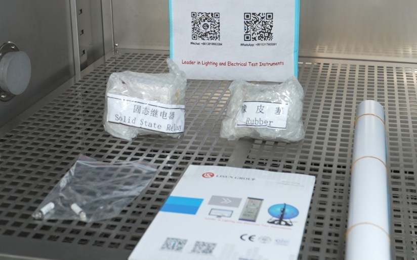
Gambar 2
Download links for the digital user manual, warranty card, and other documents have been sent via email. Please download them as soon as possible. If you missed the email, please feel free to contact us to request the download links again.
1.3 Deskripsi Struktur Peralatan
1.3.1 Tampilan Depan Ruang Uji
① Control panel; ② Test chamber door (single or double, depending on the size of the test chamber); ③ Condenser ventilation openings.
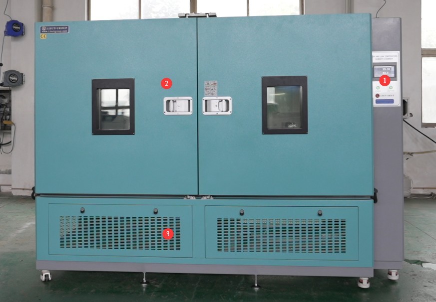
Gambar 3
1.3.2 Tampilan Belakang dan Samping Ruang Uji
① Power cord; ② Refrigerant pressure gauge; ③ This is the overflow outlet; a small amount of water will flow out during the test. Simply connect this water pipe to a drain. A water pipe with an inner diameter of 10 mm is required.
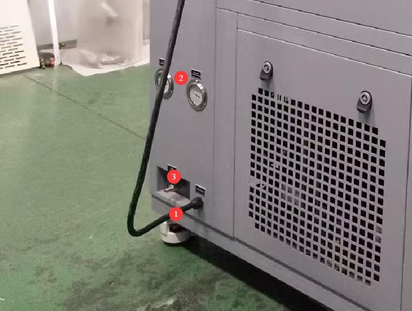
Gambar 4
2. Tindakan Pencegahan Keamanan
2.1 Keamanan Listrik
2.1.1 Koneksi Daya
The equipment must be powered by a dedicated circuit with specifications of AC 380 V, 50 Hz (or 60 Hz, optional), three-phase, five-wire system. Multiple units must not share a single power source to prevent voltage drops that could cause abnormal equipment performance or unplanned downtime. Before connecting the power supply, ensure the power is turned off. When wiring, strictly distinguish between the live wires (L1, L2, L3), neutral wire (N), and ground wire (PE). The wiring sequence must comply with the requirements of the equipment’s electrical schematic; reversing the live and neutral wires is strictly prohibited.
The equipment is equipped with a phase sequence protector. After wiring, check the phase sequence before powering on: If the green “Un” light and the yellow “R” light on the phase sequence protector are both lit, the wiring is correct; If only one of the lights is on, or none are on, this indicates reverse phase. Turn off the main power supply, swap the positions of the two adjacent live wires (L1 and L2), and then check again;
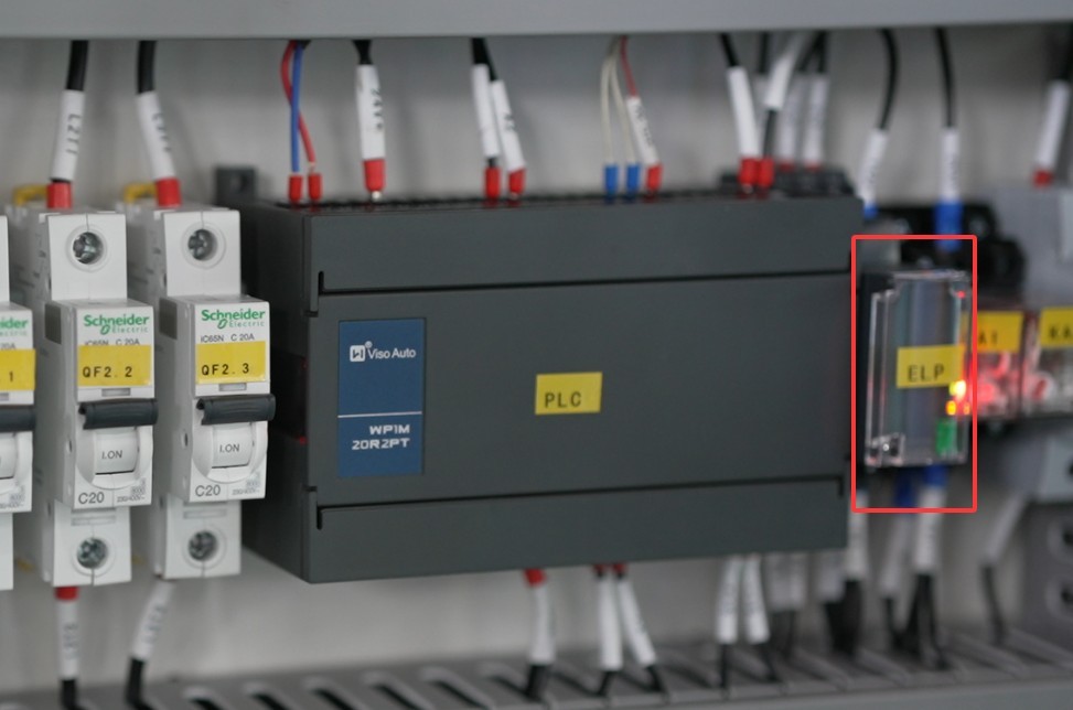
Gambar 5
Setelah menyelesaikan pemasangan kabel, tarik terminal dengan kuat untuk memastikan sambungan aman dan tidak longgar.
2.1.2 Spesifikasi Pembumian
The equipment must be reliably grounded, with a grounding resistance of ≤50 Ω. Do not use gas lines, non-metallic water pipes, or neutral wires as substitutes for the grounding wire. After grounding is complete, use a Grounding Resistance Tester to measure the grounding resistance. Power may only be applied after confirming that the requirements are met, to prevent electric shock, equipment malfunction, or measurement errors caused by poor grounding.
2.1.3 Kontraindikasi untuk Prosedur
Before wiring, inspecting, or maintaining the equipment, you must turn off the circuit breaker on the back of the equipment and disconnect the main power supply. Confirm that there is no residual voltage before proceeding;
Jangan mengoperasikan sakelar daya peralatan, layar sentuh, atau tombol instrumen dengan tangan basah untuk menghindari risiko sengatan listrik;
Jangan meletakkan benda asing apa pun (seperti perkakas atau kertas) di dalam kabinet kontrol listrik untuk mencegah debu atau benda asing menyebabkan korsleting atau merusak komponen;
Jangan mencolokkan atau mencabut kabel daya atau kabel sinyal saat peralatan sedang beroperasi untuk mencegah korsleting yang dapat merusak pengontrol atau komponen listrik.
2.2 Keselamatan Operasional
2.2.1 Persyaratan Spesimen Uji
The equipment must not be used for testing flammable, explosive, toxic, or highly corrosive substances (such as alcohol, gasoline, strong acids, strong alkalis, etc.). Since the equipment is not equipped with explosion-proof devices, such substances may cause fires, explosions, or corrosion of the equipment;
Jika spesimen uji menghasilkan panas (seperti selama pengujian daya pada komponen elektronik), sumber daya eksternal dan independen harus disediakan untuk spesimen tersebut. Jangan menggunakan catu daya perangkat itu sendiri secara langsung untuk menghindari kelebihan beban pada rangkaian perangkat;
The sample volume must not exceed 80% of the test chamber’s capacity, and the weight must not exceed the specified load capacity of the shelves (30 kilograms per shelf) to prevent deformation of the shelves or disruption of the temperature cycling process.
2.2.2 Keselamatan Operasional
While the equipment is in operation, non-professionals are prohibited from disassembling or repairing it. In the event of a malfunction, contact after-sales service personnel or operate the equipment only under the guidance of a technician;
Avoid opening the chamber door as much as possible during the test. Opening the door when the temperature is extremely high or low may cause the operator to suffer burns or frostbite, and may disrupt the temperature equilibrium inside the chamber, thereby affecting the test results. If it is necessary to open the door, wear heat-resistant gloves and safety goggles, open the door slowly, and wait until the temperature inside the chamber has stabilized before proceeding;
Do not set the temperature above the range specified for the equipment; exceeding the temperature limit may cause the heating element to burn out or even result in a fire;
If the equipment triggers an alarm (the touchscreen automatically switches to the alarm code screen), immediately stop the test and troubleshoot the issue (see “Chapter 7: Troubleshooting and Resolving Common Issues”). Do not force the equipment to restart; operating the equipment before the fault is resolved may cause further damage.
2.2.3 Perilaku yang Dilarang
Jangan membuka pintu kabinet kontrol saat peralatan sedang beroperasi untuk menghindari menyentuh komponen tegangan tinggi di dalamnya dan menyebabkan sengatan listrik;
Do not disassemble core components such as the temperature sensor (PT100 platinum resistance thermometer) or heating elements without authorization. Modifying the equipment will void the warranty and may cause safety incidents;
Jangan meletakkan benda berat (seperti perkakas, aksesori, dll.) di atas perangkat untuk menghindari kerusakan pada panel perangkat atau menghambat pembuangan panas;
Do not pile flammable items (such as cardboard boxes, plastic wrap, etc.) around the equipment. Keep the equipment’s ventilation openings clear to prevent the risk of fire.
2.3 Keselamatan Lingkungan
2.3.1 Persyaratan Instalasi
Peralatan harus dipasang di ruangan ber-AC di mana suhu lingkungan dijaga antara 5°C dan 25°C dan kelembaban relatif ≤85%. Jika kelembaban lingkungan tinggi, kondensasi dapat terbentuk di dekat pintu peralatan dan port pengujian; dalam kasus seperti itu, tingkatkan ventilasi ruangan atau gunakan alat pengering udara (dehumidifier);
The installation site must be free of high concentrations of dust, corrosive gases (such as sulfur dioxide and chlorine), and flammable or explosive atmospheres. Direct sunlight on the equipment is prohibited to prevent corrosion of the equipment housing and aging of electrical components;
Keep the device away from areas with significant fluctuations in ambient temperature, such as near vents and doorways, to prevent these fluctuations from affecting the device’s temperature control accuracy.
2.3.2 Persyaratan Ruang
The distance between the equipment enclosure and the wall, as well as surrounding fixtures (such as other test equipment and shelving), must be at least 1500 mm to ensure unobstructed ventilation at the equipment’s cooling vents (rear and sides);
At least 2000 mm of space must be left at the equipment door opening to ensure the door can be opened in any direction, facilitating the placement and removal of samples;
2.3.3 Penempatan Horizontal
The equipment must be placed on a level surface. Use a spirit level to ensure the equipment is level: Place the spirit level on the top surface of the equipment and make sure the bubble is centered. Note: The height of the following types of legs must be adjusted to ensure the test chamber is level:
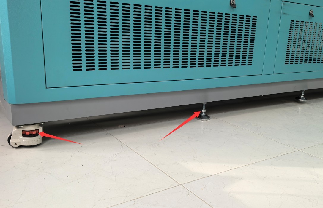
Gambar 5.1
Jika peralatan dimiringkan, hal itu dapat membahayakan stabilitas struktural ruang uji, menyebabkan distribusi suhu yang tidak merata di dalam ruang uji, atau bahkan mengakibatkan penyegelan pintu yang buruk, sehingga memengaruhi hasil pengujian dan masa pakai peralatan.
2.4 Lainnya
Untuk hal-hal yang tidak tercakup dalam panduan ini, harap berhati-hati atau hubungi kami.
3. Persiapan Sebelum Ujian
3.1 Connecting the Power Cord
Lihat 2.1.1.
3.2 Contoh Penempatan
Untuk batasan sampel, lihat Bagian 2.2.1.
Note: If the sample requires the use of a cable, please reseal the side opening on the outside of the test chamber with a rubber plug, as shown in the figure below:
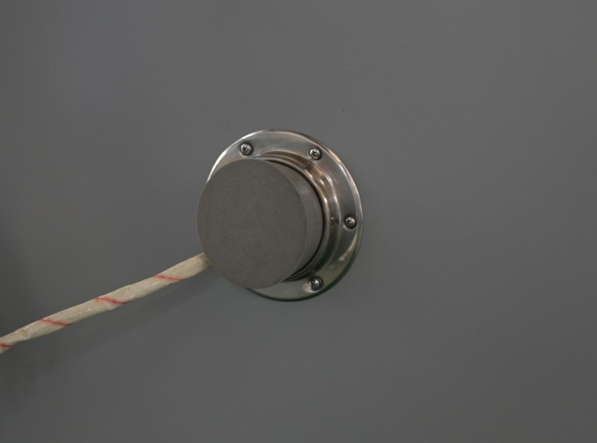
Gambar 6
Samples must not come into contact with the inner walls of the test chamber; temperature probes must not be touched or covered; and airflow channels must not be obstructed. Samples must be securely fastened and must not move during the test.
3.3 Menutup Pintu Kabinet
Make sure the box door is closed and the latch is securely locked. If it is a double door, press and lock the left door first, then press and lock the right door.
3.4 Memulai Ruang Uji
3.4.1 Turn on the power to the test chamber
Press the “Power” button on the control panel on the front of the device. The touchscreen program will enter standby mode. Ensure that there are no alarms in the program; if there are any alarms, refer to Chapter 7 for troubleshooting.
4. Program Operation via the Touchscreen of The High And Low Temperature Chamber
4.1 Introduction to the Main Screen
The system automatically enters the monitoring screen when it starts up. Click “MAIN” in the upper-right corner to access the main screen.
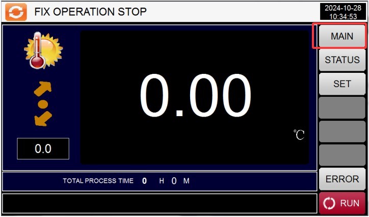
Gambar 7
From left to right and top to bottom, they are: ① Curve display; ② Monitoring screen; ③ Operation settings; ④ Program group settings; ⑤ Scheduled settings; ⑥ Display settings.
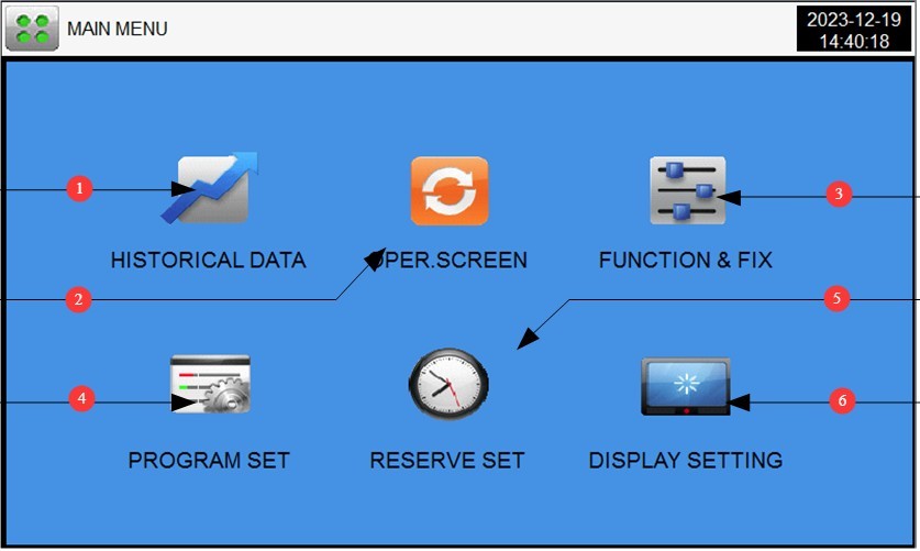
Gambar 8
4.2 Pengaturan Operasi
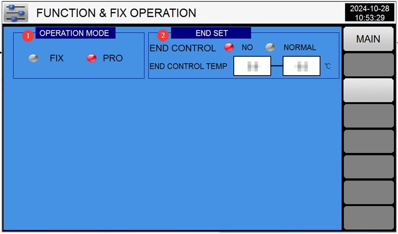
Go to the “Operation Settings” screen. ① Select the test operation mode: FIX (fixed value) or PRO (program); ② Set the test completion action: no action or return to ambient temperature. If you want the system to automatically return to ambient temperature, set the ambient temperature range.
Gambar 9
4.3 Pengaturan Janji Temu
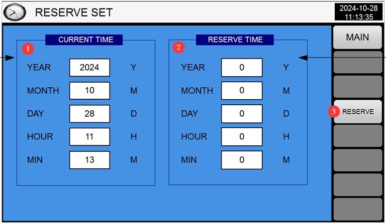
Go to the “Scheduled Settings” screen. ① The left column displays the current time; ② in the right column, enter the scheduled time. Then press the “RESERVE” button on the far right until it turns red—this confirms the schedule has been set, and the test chamber will automatically begin the test at the scheduled time.
Gambar 10
4.4 Pengaturan Tampilan
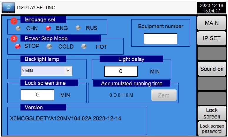
Go to the “Display Settings” screen. ① Select the display language; ② Power-off recovery mode (Stop: After a power failure during operation, the system returns to the “Stop” state when power is restored; Cold Start: After a power failure during operation, the system restarts from the first segment when power is restored; Hot Start: After a power outage interrupts operation, the system continues from the segment where operation was interrupted before the outage, restoring the system to its pre-outage state when power is restored).
Gambar 11
4.5 Fixed-Value Operation (Single Temperature and Humidity Point Test)
4.5.1 Accessing the Fixed-Value Settings
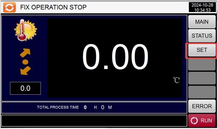
Pilih “Nilai Tetap” di “Pengaturan Operasi”. Buka “Layar Pemantauan”, lalu klik tombol “Pengaturan” di sebelah kanan untuk membuka layar “Pengaturan Nilai Tetap”.
Gambar 12
4.5.2 Pengaturan Parameter
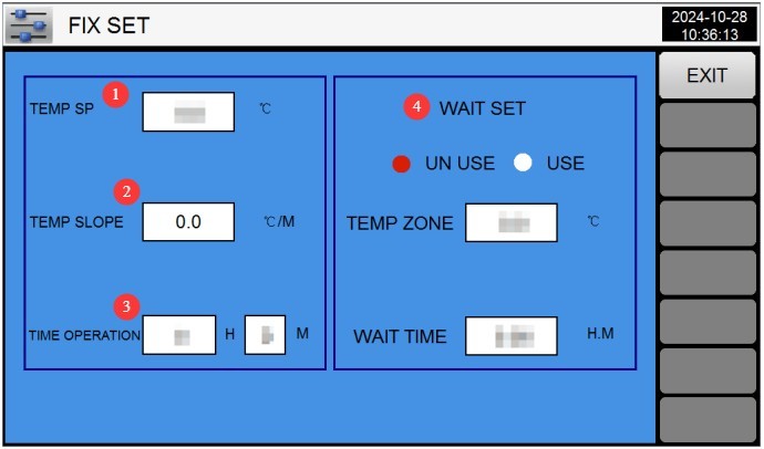
Gambar 13
① Temperature Setting: Enter the target temperature (see Section 1.1 for the configurable temperature range).
② Temperature ramp rate: Unless a specific ramp rate has been customized, use the default value of 0. The test chamber will operate using the automatic ramp rate.
③ Timed Operation: Enter the test duration (e.g., 2H; range: 0–9999H); when set to 0, the test must be stopped manually.
④ Wait Setting: If the wait function is selected, the test time will not begin until the test chamber reaches the set temperature. You must also set the wait tolerance (the test is considered complete if the temperature falls within this tolerance range) and the wait time (if the test chamber has not reached the set temperature by the end of the wait time, the test time will automatically begin).
4.5.3 Memulai Uji Kalibrasi
Setelah memastikan bahwa parameter sudah benar, kembali ke layar pemantauan dan klik tombol “Jalankan” di pojok kanan bawah.
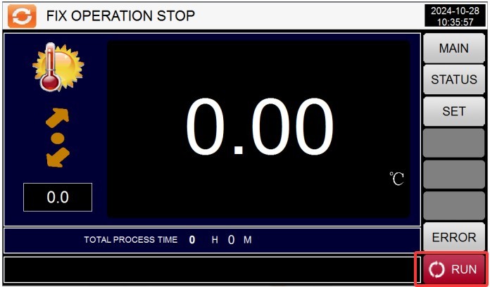
Gambar 14
4.6 Program Operation (Multi-Stage Temperature Cycling Test)
4.6.1 Program Group Settings Screen
① Nomor program: Anda dapat mengatur hingga 100 program, diberi nomor 1 hingga 100, memastikan tidak ada nomor yang tumpang tindih dengan program yang sudah ada; ② Masukkan nama program; ③ Edit program; ④ Atur pengulangan; ⑤ Atur waktu tunggu.
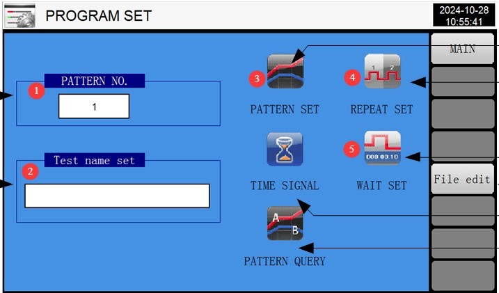
Gambar 15
4.6.2 Accessing the Program Editing Screen
① Test segment number; each program can have up to 99 test segments; ② Temperature setting; ③ Test duration setting;④ The relay is set to automatic operation; no changes are needed to the parameters here; ⑤ Switch between segment numbers; ⑥ Insert or delete a segment; ⑦ Number of segments to run in this program. For example, if you only want to run the first four segments of this program, enter 4. Please enter the correct number; otherwise, the program will not run properly; ⑧ Return to the program group settings screen.
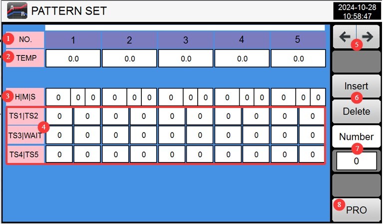
Gambar 16
Example: If you need to perform the following tests: Step
1: Temperature -20°, test duration 3 hours;
Step 2: Temperature 150°, test duration 5 hours. The
settings should be:
| NO. | 01 | 02 | 03 | 04 | 05 ... |
| Suhu | -20 ° | 150 ° | 0 | ||
| Waktu | 0.01.00 | 3.00.00 | 0.01.00 | 5.00.00 | |
NO 01: Transition phase—the time required to reach the target temperature.
NO 02: Actual test duration: 3 hours.
NO 03: Transition phase—the time required to reach the target temperature.
NO 04: Durasi tes sebenarnya—5 jam.
Note 1: For each identical temperature and humidity setting, two phases must be configured: the first is the transition phase—the time required for the test chamber to reach the set temperature—and the second is the test duration at that temperature.
Note 2: In the examples above, the transition phase was set to only 1 minute. The equipment has a wait function; even if the set time is short, the equipment will reach the set value before proceeding to the next phase. This setting minimizes the equipment’s preparation time, thereby saving test time.
4.6.3 Layar Pengaturan Loop
① Number of loops for the current program; the default value is 1, meaning the test stops immediately after the current program is completed; ② Linked program number; this specifies whether the test will automatically skip to another program to continue testing after the current program is completed. Enter 0 if this is not required; ③ Loop mode for the current program’s test segments; the default value is 0 for all segments, meaning the test does not repeat and proceeds sequentially from the first segment to the last.
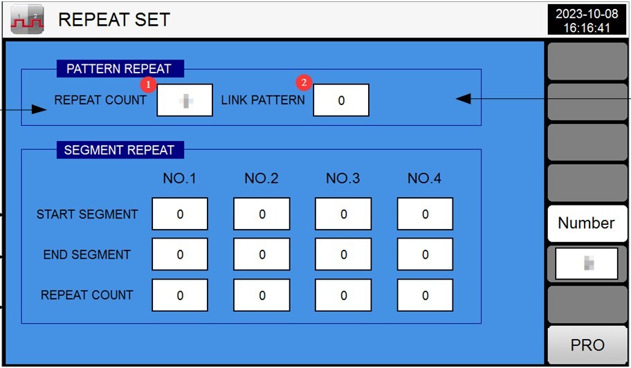
Gambar 17
Example: The figure below means: After the current program has been run twice, it will automatically proceed to Test Program 3 to continue testing.
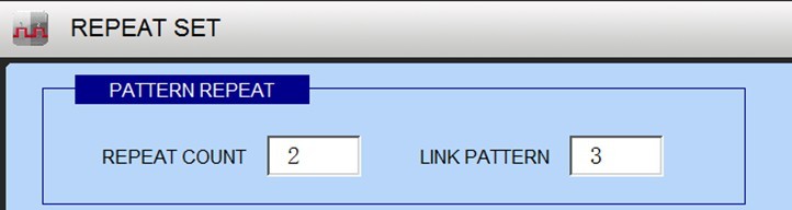
Gambar 18
The diagram below illustrates that the current test sequence for the program is 01>02>03>04>05>03>04>05>02>03>04>02>03>04>05>06>07…
Artinya, pengujian dimulai dengan segmen pertama. Bagian 3 hingga 5 diulang dua kali, diikuti oleh bagian 2 hingga 4 yang diulang dua kali, dan kemudian bagian pengujian yang tersisa diselesaikan secara berurutan.
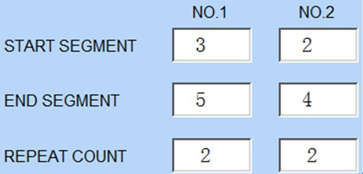
Gambar 19
Berdasarkan logika di atas, Anda dapat mengkonfigurasi parameter pengujian program untuk memenuhi kebutuhan pengujian Anda sendiri.
4.6.4 Tunggu hingga Layar Pengaturan muncul
① Pilih “SEMUA” untuk mengaktifkan fungsi tunggu untuk semua segmen pengujian; ② Nilai kesalahan zona tunggu; ③ Waktu tunggu maksimum.
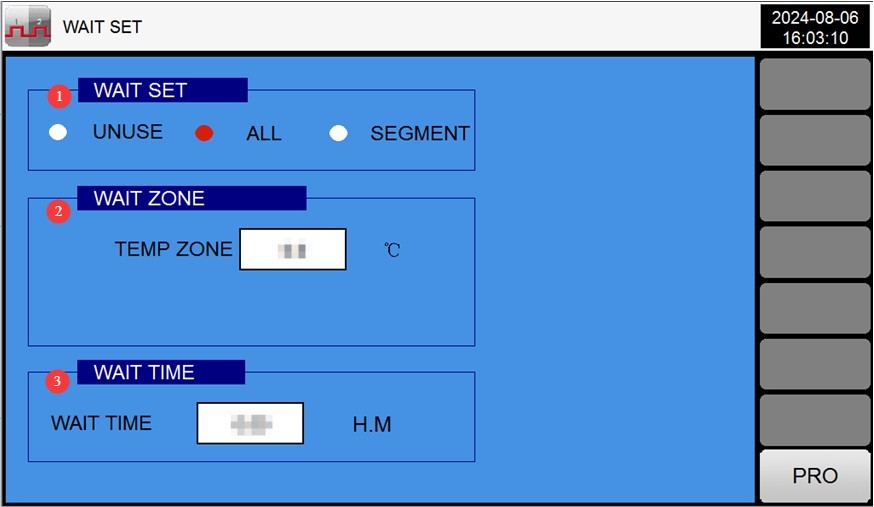
Gambar 20
4.6.5 Boot Sequence Test
Setelah memastikan bahwa parameter sudah benar, kembali ke layar pemantauan dan klik tombol “Jalankan” di pojok kanan bawah.
4.7 Test Operation and Monitoring
4.7.1 Monitoring Screen
The monitor screen displays the set temperature and the current actual temperature.
4.7.2 Pemantauan Kesalahan Secara Real-Time
If a fault occurs, the touchscreen automatically switches to the “Real-Time Fault Display Screen.”
Periksa kode kesalahan dan lihat Bab 7 untuk pemecahan masalah dan penyelesaiannya; klik “Bisukan” untuk mematikan bel, dan klik “Atur Ulang Kesalahan” setelah masalah teratasi.
4.7.3 Viewing and Exporting Curves
Tap the “Curve Display” screen on the main screen to view the real-time temperature curve.
Masukkan drive USB, klik “Unduh,” dan data kurva akan disimpan ke drive USB dalam format CSV (yang dapat dibuka dan dianalisis di komputer).
Tap “Clear History” (press and hold for 5 seconds) to delete old curve data (proceed with caution).
5. Prosedur Pasca-Ujian
5.1 Equipment Shutdown Procedures
5.1.1 Penghentian Program
Jika program berakhir secara normal: Perangkat beroperasi sesuai dengan “Mode Akhir Program” (misalnya, “Kembali ke Suhu Sekitar,” secara otomatis mendinginkan hingga kisaran suhu sekitar yang telah ditetapkan).
To stop the process midway: Click the “Stop” button on the monitoring screen, and the device will enter standby mode.
5.1.2 Prosedur Mematikan Daya
Verify that the device is in standby mode (not running), then turn off the power switch on the device’s control panel.
Matikan saklar daya utama.
5.2 Sample Removal and Handling
Wear gloves rated for high and low temperatures (even if the sample has “returned to room temperature,” it may still retain residual heat), open the chamber door, and slowly remove the sample.
Inspect the condition of the samples (e.g., appearance, performance) and record test data (temperature, humidity, time, changes in the samples).
If there is any liquid residue on the sample, wipe it clean with a lint-free cloth to prevent contamination of the work area.
5.3 Pembersihan Peralatan
Cleaning the Inner Chamber: Wipe the inner walls and shelves of the chamber with a lint-free cloth dampened with alcohol to remove any residual sample stains (do not spray water or alcohol directly onto the surfaces).
Cleaning the Refrigerator Door: Wipe down the door gasket (to remove dust) and check that the gasket is not deformed (if there are stains, wipe them off with a damp cloth).
Cleaning the Outer Case: Wipe the equipment casing with a dry cloth to remove surface dust (do not use gasoline or organic solvents, to prevent the paint from peeling).
Cleaning the Touchscreen: Wipe with a dry cloth to remove fingerprints and ensure touch sensitivity.
5.4 Catatan Tes
Fill out the equipment usage log, recording the following information: test date, program group, sample name, runtime, any malfunctions (if applicable), and operator.
Susun data pengujian (seperti grafik dan contoh laporan) dan arsipkan untuk disimpan dengan aman.
6. Pemeliharaan dan Perawatan Peralatan Harian
6.1 Pembersihan dan Perawatan Rutin
6.1.1 Routine Cleaning (After Each Test)
| Proyek Pemeliharaan | Prosedur pemeliharaan | Penting Catatan |
| Pelapis Ruang | Wipe with an alcohol-soaked lint-free cloth to remove stains | Jangan dicuci dengan air; hindari memaparkan komponen listrik pada kelembapan. |
| Strip penyegelan | Usap dengan kain kering dan periksa apakah ada perubahan bentuk atau kerusakan. | If the rubber seal is worn out (and no longer seals properly), contact customer service to have it replaced. |
| Touchscreen | Usap dengan kain kering untuk menghilangkan sidik jari dan debu. | Do not scratch the screen with sharp objects. |
| Ventilation Opening | Bersihkan debu di permukaan dengan kain kering dan pastikan ventilasi yang baik. | Do not block the ventilation openings (to prevent overheating) |
6.1.2 Pembersihan Reguler
| Proyek Pemeliharaan | Siklus Pemeliharaan | Instruksi Perawatan | Tujuan dan Persyaratan |
| Sensor suhu | Bulanan | Gunakan sikat berbulu lembut untuk menghilangkan debu dari permukaan sensor. | Measurement accuracy within ±2°C/±3% RH |
| Resistensi Tanah | Setiap 3 bulan | Grounding Resistance Tester Inspection | Resistansi tanah ≤ 50 Ω |
| Komponen listrik | Setiap 6 bulan | Open the control cabinet door and check that the relays and terminal blocks are secure. | No oxidation or loose connections; the circuit breaker is functioning normally. |
6.2 Long-Term Deactivation for Maintenance (Deactivated for More Than 1 Month)
6.2.1 Menonaktifkan Prapemrosesan
After completing all tests, turn off the power and unplug the unit as described in 5.1.2;
Thoroughly clean the equipment (inner tank, outer casing, and electrical cabinet);
Open the door of the unit and allow the inner chamber to air out and dry naturally (to prevent mold growth);
Remove all samples and shelves (if any) from the equipment and store them separately.
6.2.2 Maintenance During Downtime
Power on the unit at least once a month (for 30 minutes, to allow the circulation fan and controller to run) to prevent components from becoming damp;
Inspect the exterior of the equipment to prevent dust buildup; you may cover it with a dust cover (made of breathable material);
Inspect the storage environment to avoid humidity, high temperatures, or corrosive gases.
6.2.3 Pre-Reactivation Checks
Lepaskan penutup debu dan bersihkan peralatannya;
Check that the power lines and grounding are in good working order;
Setelah menyalakan daya, periksa apakah pengontrol, kipas, dan sistem pemanas beroperasi dengan normal;
Conduct one short-term fixed-condition test (e.g., 50°C for 30 minutes) to verify that the equipment is functioning properly before proceeding with the formal test.
7. Pemecahan Masalah dan Penyelesaian Masalah Umum
7.1 Touchscreen Alarms
| Kode Pemecahan Masalah | Kemungkinan penyebab | Solusi |
| PT1: Temperature Sensor Malfunction | The PT100 probe is faulty; its resistance at room temperature is 110 Ω; Terdapat kerusakan pada salah satu titik di modul PLC; Kabel PT100 longgar. |
Replace the PT100 probe; memperbaiki atau mengganti modul PLC; rewire |
| X2 Temperature Control Over-Temperature Protection | Korosi pada titik sambungan atau paparan air; tidak terkontrol heating, resulting in an abnormal rise in temperature; the motor is not running, preventing heat from escaping from inside the heating element; the impeller has fallen off, preventing heat from escaping from inside the heating element |
Clean or rewire; check the solid-state output; Periksa apakah ada tegangan 220V antara kabel merah dan kuning motor; jika tidak ada tegangan, ganti motor; jika ada tegangan, ganti kapasitor; reinstall the impeller |
| X3 Test Chamber Overtemperature Protection | Titik setel perlindungan suhu berlebih lebih rendah daripada titik setel pengontrol. | 1. Adjust the over-temperature protection setpoint to match that of the controller. |
7.2 Kesalahan yang Berkaitan dengan Pengontrol
7.2.1 Controller Without a Digital Display
| Gejala Kesalahan | Kemungkinan penyebab | Solusi |
| The controller screen is black; there is no display. | 1. Steker listrik tidak terhubung dengan benar; 2. Stopkontak tidak memiliki daya, atau terdapat fase yang hilang pada catu daya tiga fase; 3. Kabel pada terminal catu daya pengontrol terlepas; 4. Kerusakan internal pengontrol; 5. Pintu kabinet kontrol terbuka, menyebabkan pemutus sirkuit daya terputus. | 1. Plug the power cord in securely; 2. Check the power outlet and use a multimeter to verify that the three-phase power supply is normal; 3. Turn off the main power, open the electrical cabinet, check the wiring at the controller’s power supply terminals (e.g., 24 VAC), and retighten the connections; 4. Contact the manufacturer to repair or replace the controller;5. Close the control cabinet door, reset the circuit breaker (inside the control cabinet), and verify that it has closed. |
7.2.2 The controller displays garbled characters or the numbers flicker
| Gejala Kesalahan | Kemungkinan penyebab | Solusi |
| The display shows garbled characters or is unstable | 1. Sambungan longgar antara pengontrol dan sensor; 2. Termometer resistansi platinum (sensor suhu) rusak atau memiliki sambungan solder yang buruk; 3. Gangguan catu daya yang signifikan (misalnya, peralatan berdaya tinggi di dekatnya); 4. Kerusakan internal pengontrol | 1. Disconnect the main power supply, inspect the sensor terminals, and retighten them; 2. Replace the platinum resistance sensor (model PT100, 3-wire system, wire resistance ≤ 10 Ω), and resolder it; 3. Eliminate power supply interference (e.g., keep the device away from high-power equipment and use a regulated power supply);4. Contact the manufacturer to repair or replace the controller |
7.3 Kerusakan Sistem Pemanas
7.3.1 The unit is not heating or cooling
| Gejala Kesalahan | Kemungkinan penyebab | Solusi |
| Tanpa pemanas | 1. Over-temperature protection activated (buzzer alarm); 2. Set temperature is lower than the current actual temperature; 3. Solid-state relay failure; 4. Heating element failure; 5. Platinum resistance open circuit (no signal from the sensor); 6. Heating circuit fuse blown | 1. Check the over-temperature protection setpoint, reset it (to 20°C higher than the test temperature), and press the [Fault Reset] button; 2. Reset the temperature (to a value higher than the current actual temperature);3. Disconnect the main power supply and use a multimeter to test the solid-state relay; replace it if damaged; 4. Measure the resistance of the heating element (normally several tens of ohms); replace it if damaged; 5. Inspect the platinum resistance wire connections and replace any open-circuit platinum resistors; 6. Replace the heating circuit fuse (4 A). |
| Tidak mendinginkan | 1. The cooling switch is not turned on; 2. The compressor has not started; 3. There is a refrigerant leak | 1. Go to “Operation Settings” and turn on the cooling switch; 2. Check the compressor power supply and phase sequence, then wait 3–5 minutes before restarting; 3. Contact customer service to locate the leak and recharge the refrigerant. |
| Pendinginan lambat | 1. Insufficient refrigerant; 2. Clogged condenser; 3. Excess moisture in the chamber | 1. Top off the refrigerant (to the amount specified for the equipment); 2. Clean dust from the condenser; 3. Dry the moisture from the chamber before lowering the temperature |
7.3.2 Pemanasan yang Tidak Terkendali (Kenaikan Suhu yang Berkelanjutan)
| Gejala Kesalahan | Kemungkinan penyebab | Solusi |
| The temperature exceeds the set value and continues to rise | 1. The temperature setpoint is too high (exceeds the equipment’s upper limit); 2. The solid-state relay is stuck (cannot open); 3. The platinum resistance sensor is shorted (abnormal sensor signal); 4. Controller malfunction (cannot output a stop signal) | 1. Immediately turn off the main power supply and reset the temperature; 2. Replace the solid-state relay; 3. Inspect the platinum resistance thermometers and replace any that are shorted; 4. Contact the manufacturer to repair or replace the controller |
7.4 Abnormal Operating Conditions and Malfunctions
7.4.1 The Circulation Fan Is Not Running
| Gejala Kesalahan | Kemungkinan penyebab | Solusi |
| The fan is not rotating and is silent. | 1. The fan’s power supply wiring has come loose; 2. The fan’s overcurrent protection has tripped (thermal relay tripped); 3. The fan motor is damaged; 4. The controller is not sending a signal to start the fan | 1. Turn off the main power supply, check the fan’s terminal connections, and retighten them; 2. Reset the thermal relay (inside the electrical cabinet) and check whether the fan is jammed; 3. Test the fan motor’s resistance (which should normally be several tens of ohms); if it is damaged, replace it; 4. Check the fan control parameters on the controller and contact the manufacturer for troubleshooting. |
7.4.2 Poor Cabinet Door Seal (Temperature Leakage)
| Gejala Kesalahan | Kemungkinan penyebab | Solusi |
| Fluktuasi suhu yang signifikan selama pengoperasian; pemanasan lambat. | 1. The door gasket is worn or damaged; 2. The door hinges are loose, causing the door to be crooked; 3. The door latch is loose and does not close securely | 1. Replace aged or damaged weatherstripping; 2. Adjust the cabinet door hinges and tighten the screws to ensure the door is plumb; 3. Adjust the position of the latch to ensure the weatherstripping is pressed tightly against the door when it is closed. |
7.5 Communication Failure (PLC No Response)
7.5.1 Gangguan Komunikasi (Layar menampilkan “PLC tidak merespons”)
| Gejala Kesalahan | Kemungkinan penyebab | Solusi |
| Communication between the touchscreen and the PLC has been interrupted; control is not possible. | 1. The communication cable (RS-485) is loose or disconnected; 2. The communication cable is damaged (e.g., broken or shorted); 3. PLC power failure; 4. Mismatched communication parameters (e.g., baud rate, address) | 1. Disconnect the main power supply, inspect the RS-485 communication cable terminals, and retighten them; 2. Replace the damaged communication cable (use shielded cable to reduce interference); 3. Check the PLC power supply (e.g., 24V) to ensure it is functioning properly;4. Check the communication parameters (baud rate, address) between the controller and the PLC to ensure they match, and contact the manufacturer for guidance on adjustments |
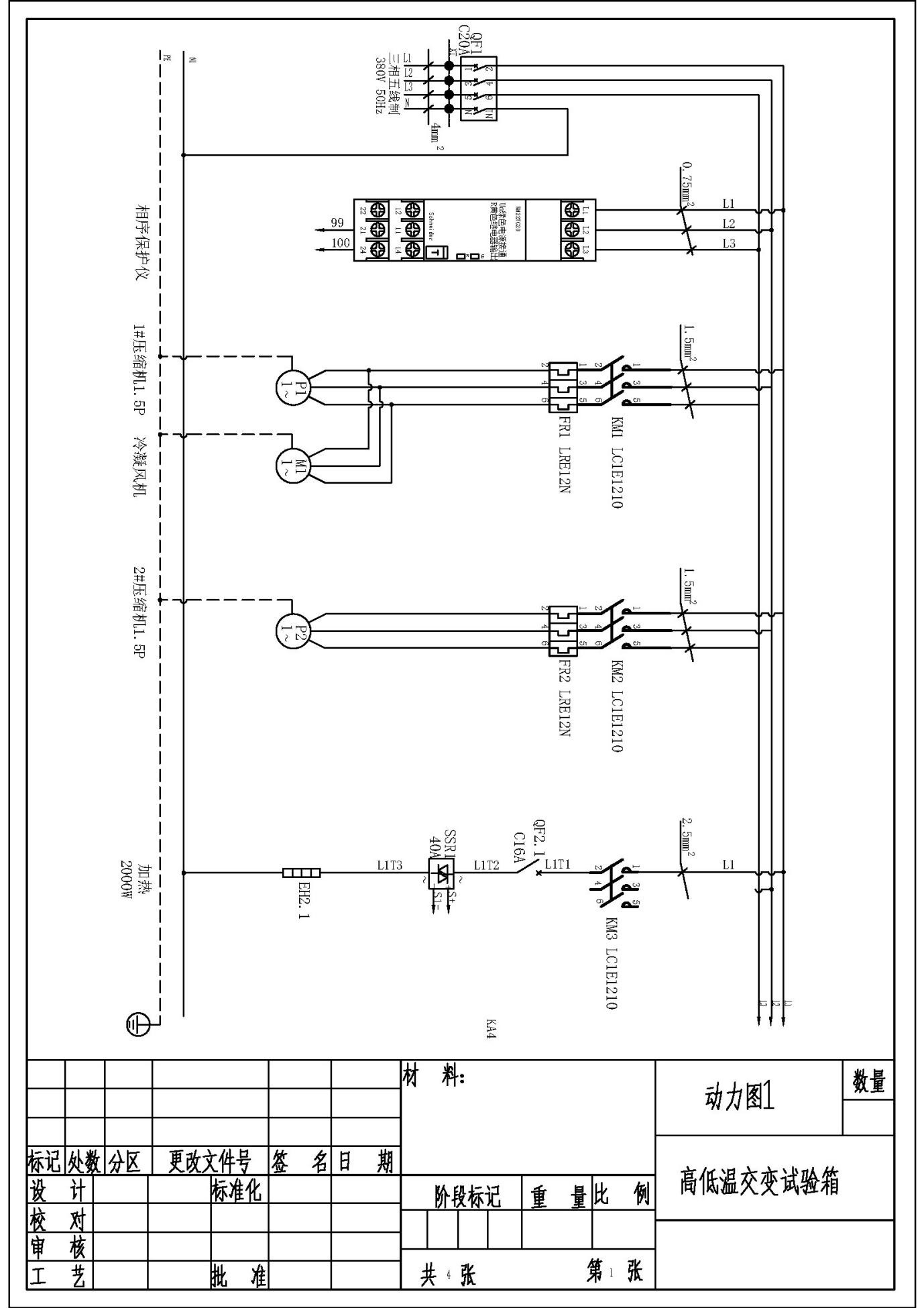
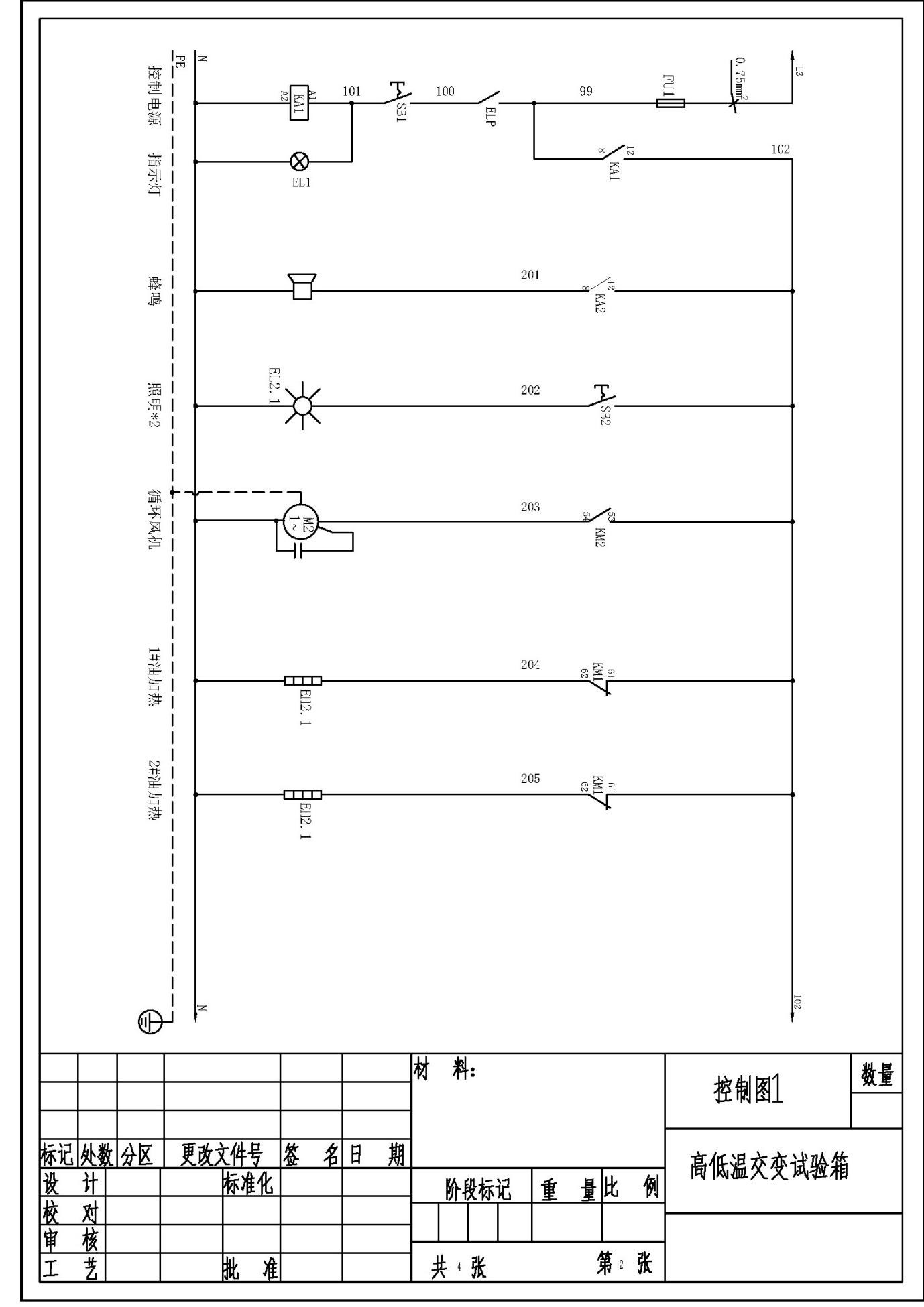
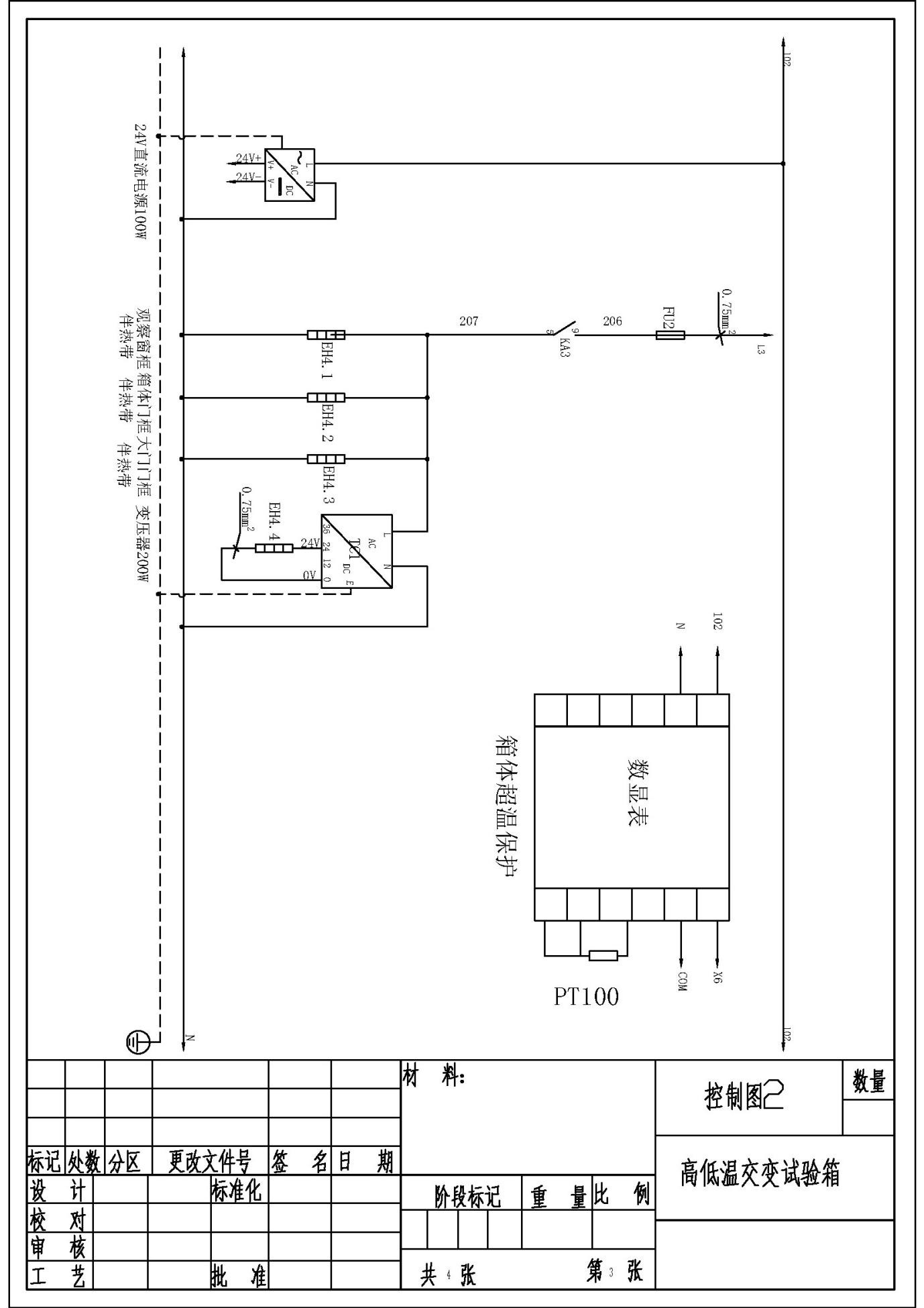
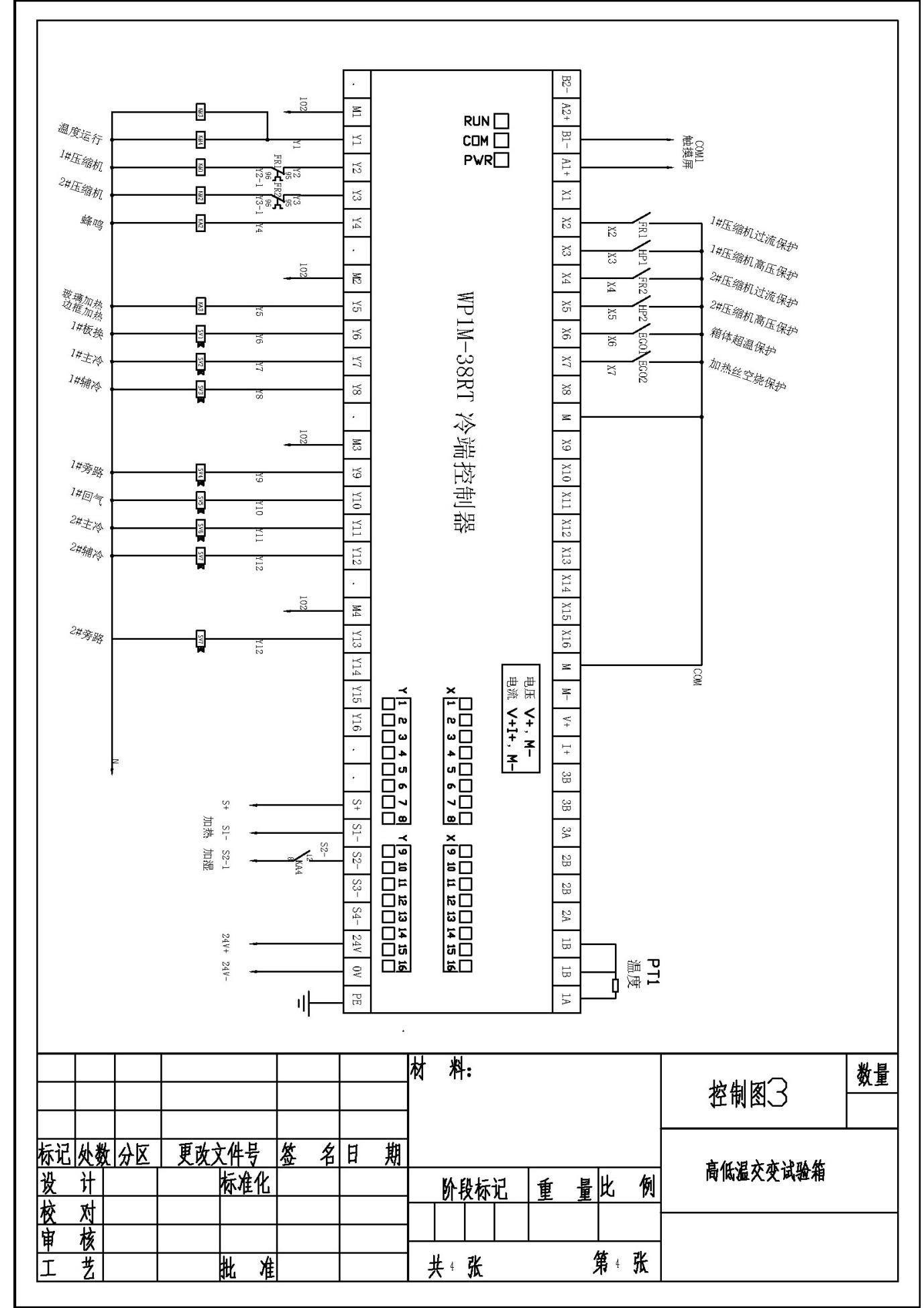
Appendix: Electrical Schematics