
 Inggris
 中文简体
中文简体 Русский
 Español
 Português
 Türkçe
 العربية
 Deutsch
 Polski
 Italiano
 Français
 한국어
한국어 ไทย
ไทย Tiếng Việt
 日本語
日本語





























Simulator Pelepasan Elektrostatis
Pengguna manual
berlaku LISUN Model: ESD61000-2,ESD61000-2A,ESD61000-2C
1. Membuka Kemasan dan Mengenal Peralatan Secara Dasar
1.1 Spesifikasi Teknis Utama
| LISUN Pilih Model | ESD61000-2 | ESD61000-2A | ESD61000-2C |
| Relay Brands | Chinese Brand: Mechanical life of approximately 200000 cycles | Kilovac (U. S.): Mechanical life of approximately 1 million cycles | |
| Tegangan Output | 0.1–20 kV ±5% | 0.1–30 kV ±5% | |
| Polaritas Tegangan Keluaran | Positif, Negatif, Bergantian Positif dan Negatif | ||
| Resistor-Capacitor Kit | 150 pF/330 Ω (dapat diganti) | 150 pF/330 Ω, 150 pF/2000 Ω, 330 pF/2000 Ω, and 330 pF/330 Ω (interchangeable) | |
| Waktu Kenaikan Arus Pelepasan | 0.6–1 ns | ||
| Fitur Pengujian | Single Test, Count Test, 20 PPS, IEC Level, Programming Mode, Custom Mode, Contact Discharge, Air Discharge, Interval Discharge | ||
| Mode Pemicu | Manual / Otomatis | ||
| Jumlah Pelepasan | 1-9999 | ||
| Interval Pelepasan | 0.05 s–99.99 s | ||
| Elektroda pelepasan | Elektroda ujung runcing (pelepasan kontak), elektroda ujung bulat (pelepasan udara) | Pointed-tip electrode (contact discharge), round-tip electrode (air discharge), large round-tip electrode with a diameter of 30 mm (air discharge) | |
| Sumber Daya listrik | AC 100 V–240 V, 50/60 Hz | ||
| Memenuhi standar | GB/T 17626.2 (IEC/EN 61000-4-2) | Elektronik Otomotif GB/T 19951 (ISO 10605), GB/T 17626.2 (IEC/EN 61000-4-2) | |
1.2 Membuka Kemasan dan Memeriksa Isinya
1.2.1 Membuka Kemasan dan Pemeriksaan Visual
Saat membuka kemasan perangkat, tangani dengan hati-hati untuk menghindari goresan pada casing luar dengan alat yang tajam. Setelah membuka kemasan, periksa terlebih dahulu bagian luar perangkat untuk memastikan tidak ada deformasi atau penyok yang terlihat, dan tombol-tombolnya tidak rusak atau longgar.
If you notice any damage or deformation to the device or its accessories, do not turn it on. Please contact us immediately.
1.2.2 Unit Utama dan Aksesoris
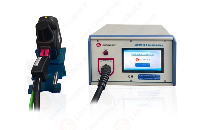
Host Devices: ESD61000-2 Series Electrostatic Discharge Simulators, as shown below:
Gambar 1
Note: The main unit of the Electrostatic Discharge Simulator and the electrostatic discharge gun are integrated into a single unit and cannot be disassembled.
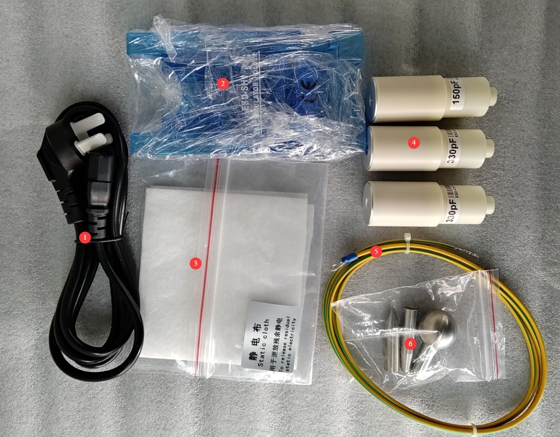
Standard accessories include: ① power cord; ② electrostatic gun mount; ③ electrostatic cloth; ④ replaceable resistor-capacitor kit; ⑤ ground wire; ⑥ pointed electrode (contact discharge), round-tip electrode (air discharge), and 30mm-diameter large round-tip electrode (air discharge).
Gambar 2
Note: Only the ESD61000-2C model includes multiple interchangeable RC kits and a large 30mm-diameter round-head electrode.
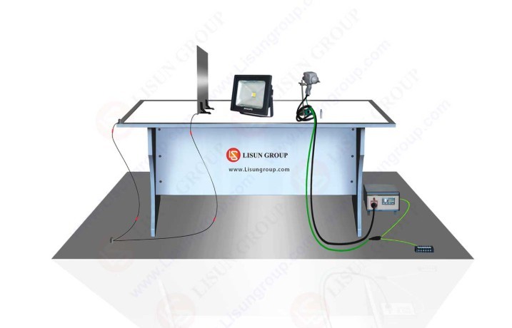
Optional Equipment 1: ESD-DESK Electrostatic Test Bench; the electrostatic test bench includes the following accessories.
| Aksesoris | Note |
| Tes Bench | Dimensi setelah dirakit: 1600 × 800 × 800 mm |
| Pelat Pembumian Logam Referensi | Panjang 2800 × Lebar 1800 × Tebal 1.0 mm |
| Pelat Kopling Vertikal | 500 (P) × 500 (L) × 1.0 mm (Ketebalan) |
| Pelat Kopling Horizontal | Panjang 1600 × Lebar 800 × Tebal 1.0 mm |
| Matras Berinsulasi | Panjang 1450 × Lebar 600 × Tebal 0.5 mm |
| Kabel Resistor 470 kΩ | Panjang 1400 mm, dua bagian |
Gambar 3
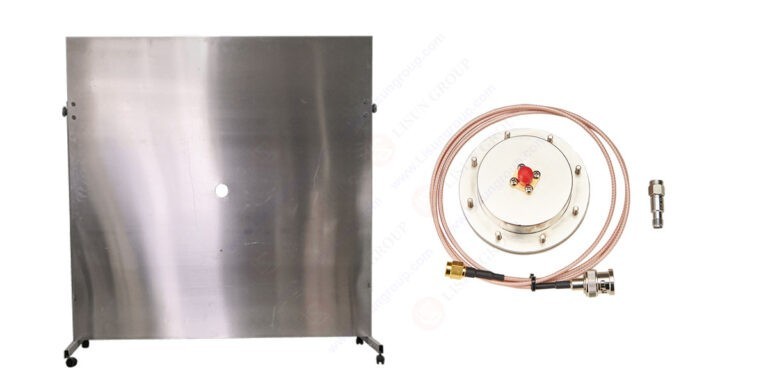
Optional Equipment 2: ESD-CALA Electrostatic Discharge Gun Calibration Kit, as shown below:
Gambar 4
Optional Equipment 3: ESD-FCP Automotive Electronic Electrostatic Field Coupling Plate, as shown below:
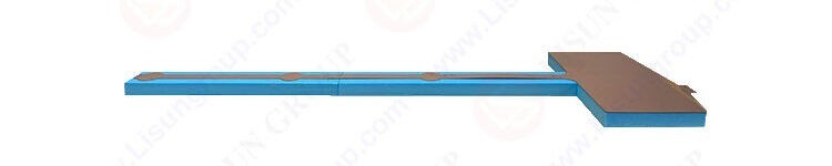
Gambar 5
Tautan unduhan untuk manual pengguna digital, kartu garansi, dan dokumen lainnya telah dikirimkan kepada Anda melalui email. Silakan unduh sesegera mungkin. Jika Anda melewatkan email tersebut, jangan ragu untuk menghubungi kami untuk meminta tautan unduhan lagi.
2. Tindakan Pencegahan Keamanan
2.1 Pedoman Penempatan
Letakkan di permukaan kerja yang stabil; hindari memiringkan atau membalikkannya, dan jauhkan dari sumber getaran;
The equipment must be placed at least 500 mm away from walls and surrounding structures (such as other testing equipment and shelving) to facilitate maintenance; at least 1000 mm of space must be left in front of the equipment to ensure smooth operation, and the surrounding area must be free of obstructions.
2.2 Standar Keselamatan Tegangan Tinggi
2.2.1 Pemeriksaan Keamanan
Pastikan catu daya kompatibel dengan peralatan, pastikan catu daya terhubung ke ground dengan benar, dan periksa apakah kabel ground tidak rusak atau longgar;
Grounding Requirements: The host unit’s protective grounding terminal (PGND) must be connected to a metal reference grounding plate; the grounding resistance must be ≤4Ω; the grounding cable must be securely connected, with no looseness or breaks;
Perlu diperhatikan bahwa pelat pentanahan referensi dan pelat penghubung harus dihubungkan ke pentanahan pelindung, dan semua sambungan pentanahan harus memiliki impedansi rendah untuk mencegah terjadinya perbedaan potensial selama pelepasan muatan;
2.2.2 Persyaratan Keselamatan untuk Prosedur Operasional
Operators must undergo professional training and be familiar with this manual and the relevant standards. Non-professionals are prohibited from operating or disassembling the equipment. The equipment contains high-voltage circuits; opening the cover may pose an electric shock hazard. Contact the manufacturer’s technical staff for repairs;
Setelah peralatan dinyalakan, jangan sentuh ujung elektroda pistol pelepasan, konektor tegangan tinggi, atau kabel tegangan tinggi;
Operators should ensure their hands are dry and free of metal jewelry; it is recommended that they wear insulated gloves while working;
Selama pengujian, personel yang tidak berwenang dilarang berada dalam jarak 1 meter dari EUT untuk mencegah sengatan listrik yang tidak disengaja atau gangguan dari pelepasan listrik;
Before replacing the electrodes, you must first ensure that the high-voltage output has been turned off (the HV indicator light is off) and wait at least 5 minutes to ensure that the internal high-voltage capacitor is completely discharged;
Do not eat or drink during the test to prevent accidents caused by electric shock;
When multiple people are involved, clearly define roles and responsibilities, and confirm with each other before the test begins to avoid errors.
2.3 Lainnya
Untuk hal-hal yang tidak tercakup dalam panduan ini, harap berhati-hati atau hubungi kami.
3. Ikhtisar Peralatan
3.1 Pengantar Panel Depan
| Jumlah | Note |
| ① | Touchscreen |
| ② | High-Voltage Indicator Light |
| ③ | Static discharge gun and grounding clamp—not removable |
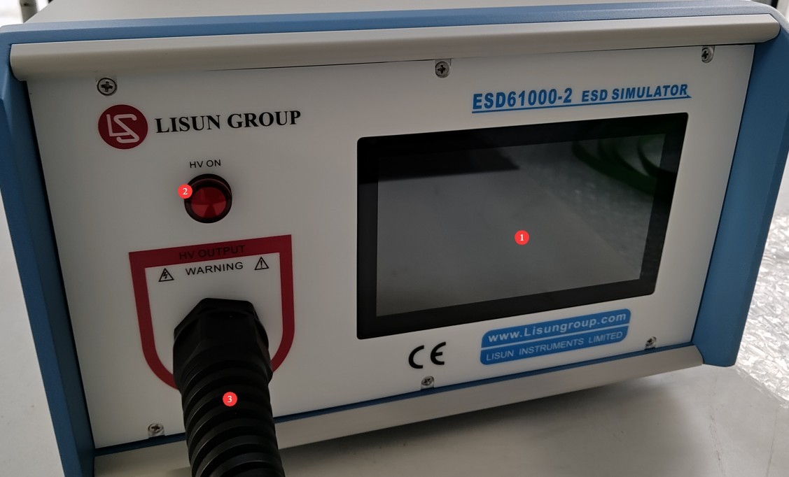
Gambar 5.1
3.2 Pengenalan Panel Belakang
| Jumlah | Note |
| ① | Power cord receptacle (with fuse) for connecting the device to a suitable power source |
| ② | Saklar daya |
| ③ | Terminal Ground Pelindung PGND |
| ④ | USB port: Allows you to connect a USB mouse to control the touchscreen, or a USB flash drive to update the software |
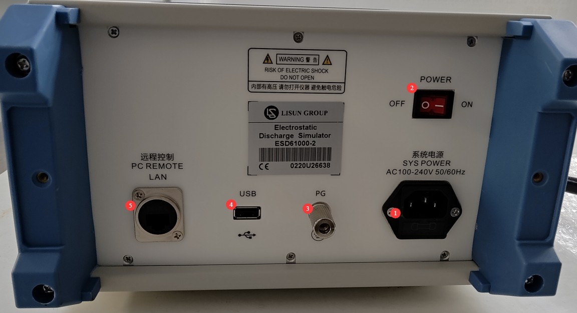
Gambar 5.2
4. Pengantar Program Layar Sentuh
4.1 Layar Awal
Turn on the device and wait a moment. Once the program has finished loading, it will automatically open the initial screen: ① Switch between Chinese and English; ② Access the parameter settings screen; ③ Product information page.
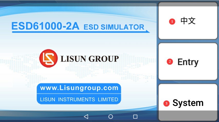
Gambar 10
4.2 Antarmuka Pengaturan Parameter
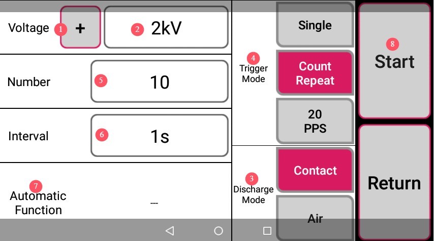
① Discharge polarity setting; ② Discharge voltage setting; ③ Discharge mode selection: Contact Discharge or Air Discharge. This interface uses Contact Discharge as an example; ④ Trigger mode selection: Trigger mode can only be selected in Contact Discharge mode. In Air Discharge mode, according to standards, only the “Single” trigger mode can be used;⑤ Discharge count setting; ⑥ Discharge interval setting; ⑦ If automatic functions (automatic polarity switching, automatic voltage switching) are required, click here to configure them; ⑧ After clicking “Start,” the device will enter the charging state.
Gambar 11
Regarding trigger modes:
“Single” means one discharge occurs each time the trigger of the discharge gun is pulled;
“Repeat” means that after the trigger is pulled and released, the instrument enters an automatic repeat discharge mode and counts the number of discharges; once the set number of discharges is reached, it automatically exits the discharge mode. Pressing and releasing the trigger again during this period will pause the discharges; pressing and releasing it once more will resume discharges, and the count will continue.
“20PPS” refers to the 0.05-second rapid scan mode, which operates the same way as the “Repeat” mode, except that it automatically performs repeated discharges at 0.05-second intervals.
4.3 Automatic Function Interface
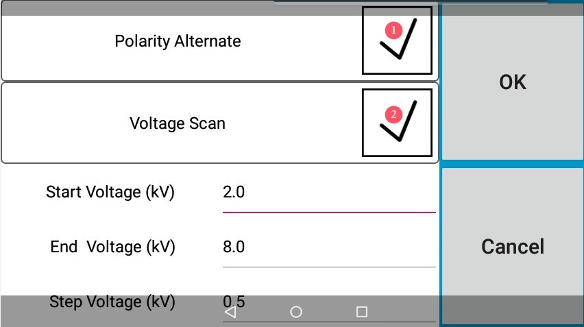
① Check the “Polarity Switching” box to automatically switch polarity during the test; ② Check the “Voltage Scan” box and enter the start voltage, end voltage, and step voltage in the input fields; the test will then run automatically according to the settings.
Gambar 12
4.4 Charging and Testing Interface
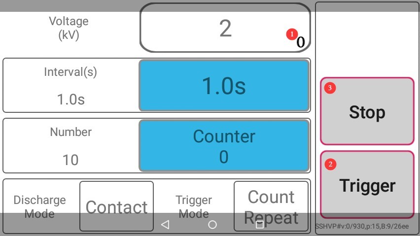
① Testing may only begin after charging is complete—that is, once 100% is displayed here—and the high-voltage indicator light on the front of the main unit illuminates; ② Once charging is complete, click “Trigger” or pull the trigger on the discharge gun to perform an electrostatic discharge test; ③ Click “Stop” to return to the parameter settings screen.
Gambar 13
Note 1: When the trigger mode is set to “single shot,” the interval between trigger pulls must be at least 1 second.
Note 2: When testing using the automatic function, the program will automatically return to the parameter settings screen when switching polarity or voltage, without requiring any manual intervention. It will then automatically proceed to the charging and testing screen. Only after the device has finished recharging can you click “Trigger” or pull the trigger on the discharge gun to continue the test.
5. Persiapan Sebelum Ujian
5.1 Persiapan Lingkungan Pengujian
Suhu: Atur suhu laboratorium menjadi 23°C ± 2°C;
Kelembapan: Gunakan alat pengering udara (dehumidifier) atau pelembap udara (humidifier) untuk menjaga kelembapan relatif antara 45% dan 75%; pengujian di lingkungan tempat terjadinya kondensasi dilarang;
The premises must be free of strong electromagnetic interference, corrosive gases, flammable or explosive materials, and dust, and must be well-ventilated to prevent sparks from causing hazards;
Tekanan atmosfer: Pastikan berada dalam kisaran 86–106 kPa. Jika laboratorium terletak di ketinggian, catat nilai tekanan atmosfer untuk dicantumkan dalam laporan pengujian.
5.2 Connecting Devices
5.2.1 Penempatan Peralatan
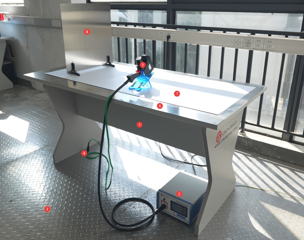
① Metal reference ground plate; ② Electrostatic Discharge Simulator; ③ ESD discharge gun; ④ Discharge gun ground clamp; ⑤ Wooden test table; ⑥ Horizontal coupling plate (HCP); ⑦ Insulating mat; ⑧ Vertical coupling plate (VCP).
Gambar 6
5.2.2 Sambungan Sistem Pembumian
Main Unit Grounding: Use a grounding wire to securely connect the PGND terminal on the back of the main unit to a metal reference ground plate, ensuring good contact;
Menghubungkan Pistol Pelepasan ke Ground: Hubungkan klem ground pistol pelepasan ke pelat ground referensi logam untuk mencegah interferensi yang diinduksi;
Coupling Plate Grounding: The horizontal and vertical coupling plates are connected to the reference metal grounding plane via 470 kΩ resistive cables. The resistors must be securely fastened, capable of withstanding the test voltage, and protected against short circuits.
Pengardean melalui Pelat Pengardean Logam Referensi: Pelat pengardean logam referensi harus terhubung dengan aman ke tanah untuk memastikan bahwa resistansi pengardean semua kabel pengardean ≤4 Ω.
5.2.3 Installation of Discharge Gun Accessories
Mengganti Elektroda: Ganti elektroda yang sesuai jika diperlukan. Untuk melepas elektroda, putar berlawanan arah jarum jam; untuk memasangnya, putar searah jarum jam.
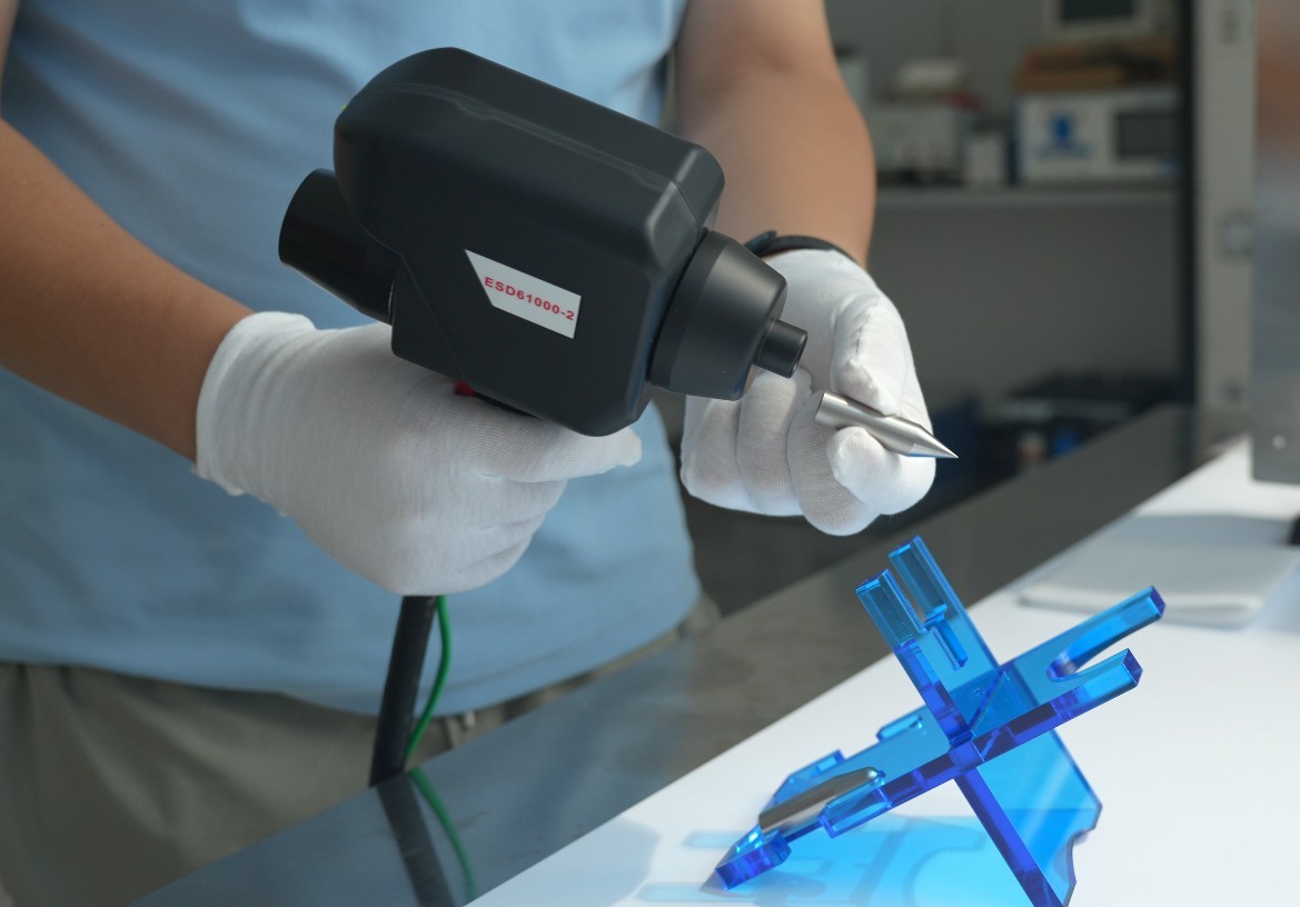
Gambar 7
Replacing the Resistor-Capacitor Kit: If you have purchased multiple resistor-capacitor kits, unscrew the cover of the kit marked in the image below by turning it counterclockwise:
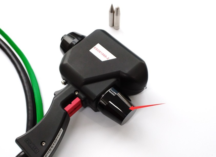
Gambar 8
Replace the corresponding resistor-capacitor assembly, then reinstall it by turning it clockwise.
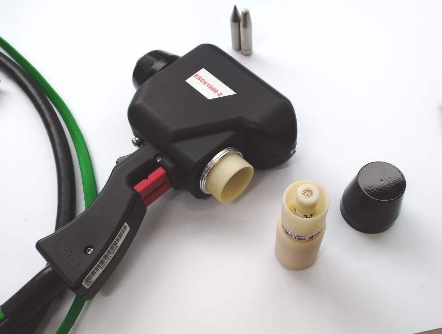
Gambar 9
5.3 Persiapan EUT (Peralatan yang Sedang Diuji)
5.3.1 Pemasangan dan Pengamanan EUT
Jarak antara EUT (Equipment Under Test) dan dinding, benda konduktif lainnya (termasuk operator), harus minimal 1 m;
Benchtop EUT: Place the EUT on a 0.5 mm-thick insulating mat positioned above the horizontal coupling plate. The distance between the edge of the EUT and the edge of the coupling plate shall be no less than 0.1 m. If the EUT is too large, two test benches may be joined together, provided that the overlapping portion of the coupling plates is no less than 0.3 m;
Floor-mounted EUT: Place the EUT on a 0.1 m thick insulating mat positioned above the metal reference ground plate. The distance between the EUT and the vertical coupling plate shall be 0.1 m, and the dimensions of the vertical coupling plate shall be 0.5 × 0.5 m²;
The EUT must be securely fastened to prevent displacement during testing, while maintaining its normal installation configuration (e.g., mounting brackets and wiring methods consistent with actual use).
5.3.2 Catu Daya dan Pengkabelan EUT
Connect the power supply in accordance with the EUT’s rated power supply requirements. Route the power cord according to the actual usage conditions to prevent it from becoming tangled with the discharge gun cable;
If the EUT requires a signal cable, the signal cable must be kept away from the reference metal ground plane and the coupling plate, and its length must correspond to the actual application; use shielded cable and ground it properly when necessary;
The EUT must be powered on and allowed to warm up in advance to reach its normal operating state (e.g., by running the test software and outputting the rated signal) to ensure it is in a stable operating mode during testing.
5.4 Konfirmasi Standar dan Prosedur Pengujian
5.4.1 Penentuan Tingkat Keparahan
Berdasarkan lingkungan instalasi dan skenario penggunaan EUT, pilih tingkat keparahan sesuai dengan GB/T 17626.2-2018. Tingkat keparahan umum adalah sebagai berikut:
| Tingkat Keparahan | Tegangan Pelepasan Kontak (kV) | Tegangan Pelepasan Udara (kV) | Skenario yang Berlaku |
| Level 1 | 2 | Lingkungan dengan kelembapan tinggi (≥35%) dan tanpa kain sintetis | |
| Level 2 | 4 | Kelembapan sedang (10%–35%) dan lingkungan dengan sedikit kain sintetis. | |
| Level 3 | 6 | 8 | Environments with low humidity (≤50%) and a high proportion of synthetic fabrics (e.g., offices) |
| Level 4 | 8 | 15 | Kelembapan rendah (≤10%) dan lingkungan dengan konsentrasi kain sintetis yang tinggi (seperti ruang pengeringan) |
| Kelas Khusus | Kustom | Akan ditentukan melalui konsultasi antara produsen dan pengguna. | |
5.4.2 Test Modes and Parameter Design
Discharge Mode: Determine whether to use contact discharge (conductive surface of the EUT), air discharge (insulating surface of the EUT or socket), or indirect discharge (discharge via a coupling plate).
Key Parameters: Discharge voltage, polarity (positive/negative/alternating), number of discharges (typically 10 per point for single-polarity), discharge interval (1 s for standard mode, 0.05 s for fast scanning), trigger mode (contact discharge: single/repeat/20 PPS; air discharge: single only).
Note: When the trigger mode is set to 20 PPS, the discharge interval automatically changes to 0.05 s.
Perencanaan Titik Uji: Cantumkan titik uji utama pada EUT, seperti permukaan konduktif yang mudah diakses, permukaan terisolasi, dan soket, untuk memastikan cakupan semua area yang mungkin bersentuhan dengan operator (lihat Lampiran A dari GB/T 17626.2-2018).
6. Prosedur Operasi untuk Pengujian Pelepasan Muatan Elektrostatik (Referensi: GB/T 17626.2-2018)
6.1 Uji Pelepasan Kontak (Pengujian Permukaan Konduktif EUT)
Pegang pistol pelepasan dan posisikan ujung elektroda berbentuk kerucut secara vertikal terhadap titik uji konduktif EUT, pastikan kontak yang baik (tidak ada celah);
Pull the trigger of the discharge gun (single-shot mode) or pull and release the trigger once (continuous/20 PPS mode) to complete a single discharge or a continuous discharge;
Setelah menembakkan sejumlah peluru yang ditentukan pada setiap titik uji, pindahkan pistol penembak ke titik uji berikutnya dan ulangi pengujian;
Selama pengujian, amati status pengoperasian EUT secara real-time (misalnya, apakah tampilan berfungsi normal, apakah ada kesalahan yang dilaporkan, dan apakah ada fungsi yang terganggu), dan catat setiap anomali.
Note: In single-discharge mode, to simulate a single electrostatic discharge, the charge on the test equipment should be removed using an antistatic cloth before each electrostatic discharge pulse is applied.
6.2 Uji Pelepasan Udara (Uji Permukaan Isolasi/Soket EUT)
Hold the discharge gun and position the spherical electrode tip away from the EUT test point (at a distance of at least the voltage-corresponding distance—1 mm for 1 kV; for example, 15 kV requires a distance of at least 15 mm);
Pull the trigger of the discharge gun and hold it down, slowly moving toward the test point at an angle perpendicular to the EUT’s surface until a discharge spark occurs;
Immediately after the spark is generated, release the trigger and pull the discharge gun backward (to prevent multiple discharges), thereby completing a single air discharge;
After a 1-second interval, perform the next discharge test until the specified number of discharges is completed (10 discharges per point, 5 each for positive and negative polarities, or as required by the standard);
Selama pengujian, amati apakah EUT menunjukkan kelainan fungsional apa pun, dan catat lokasi titik pelepasan dan sifat kelainan tersebut.
Note: In single-discharge mode, to simulate a single electrostatic discharge, the charge on the device under test should be removed using an antistatic cloth before applying each electrostatic discharge pulse.
6.3 Uji Pelepasan Tidak Langsung (Uji Pelepasan Pelat Terhubung)
6.3.1 Pengaturan Parameter
Set the discharge mode to “Contact” and the trigger mode to “Repeat”;
Enter the discharge voltage (based on the severity level), the number of discharges (10 per side), and the discharge interval (1 s);
6.3.2 Discharge Operation
Place the conical electrode tip of the discharge gun in vertical contact with the surface of the coupling plate (select 3 discharge points evenly spaced across the horizontal coupling plate and 2 discharge points on the vertical coupling plate);
Pull the trigger to start continuous discharge; after completing the set number of discharges, move to the next discharge point;
Setelah menyelesaikan pengujian titik pelepasan pada semua pelat penghubung, catat apakah EUT terpengaruh oleh interferensi pelepasan tidak langsung.
6.4 Recording of Test Results
Lihat Lampiran B dari GB/T 17626.2-2018:
| Tingkat | Definisi | Dengan keputusan |
| A | Berfungsi normal sesuai dengan batasan yang ditentukan oleh produsen, klien, atau pembeli. | Lulus tanpa syarat |
| B | Kehilangan atau penurunan fungsi atau kinerja sementara yang akan pulih dengan sendirinya setelah gangguan berhenti, tanpa memerlukan intervensi operator. | Membutuhkan konsultasi dengan produsen/pengguna; umumnya dianggap disetujui. |
| C | A temporary loss or reduction in function or performance that requires operator intervention or a system reset to restore normal operation. | This must be discussed with the manufacturer/user, depending on the application. |
| D | Hilangnya fungsi atau penurunan kinerja akibat kerusakan perangkat keras atau perangkat lunak, atau kehilangan data. | Kegagalan Tanpa Syarat |
7. Prosedur Pasca-Ujian
7.1 Prosedur Penghentian Pengujian
Once all test points have been completed, or when you click “Stop” to end the test, the high-voltage indicator light will turn off, and the program will automatically return to the parameter settings screen;
Matikan daya ke EUT, dan lepaskan EUT dari catu daya dan kabel sinyal;
Ganti EUT dengan yang lain untuk pengujian, atau matikan sakelar daya pada unit utama Simulator Pelepasan Muatan Elektrostatik.
7.2 Pengorganisasian Peralatan dan Ruang Kerja
Remove the discharge electrode tip, clean it (to remove any dirt from the tip), and store it properly (to prevent wear on the tip);
Clean the surface of the main unit (wipe it down with a dry, soft cloth), the discharge gun, the coupling plate, the reference metal grounding plate, and other components.
7.3 Persyaratan Penyimpanan Jangka Panjang
Saat peralatan tidak digunakan dalam jangka waktu lama, peralatan tersebut harus disimpan di lingkungan yang kering dan berventilasi baik (suhu 10°C–40°C, kelembapan relatif ≤60%) untuk menghindari kelembapan, getaran, dan sinar matahari langsung;
Before storage, disconnect all connections, pack components such as the electrode head, cables, and coupling plate separately, and place a dust cover over the main unit;
Turn on the device for 30 minutes each month to prevent internal components from becoming damp and deteriorating.
8. Pemeliharaan dan Perawatan Peralatan Harian
8.1 Perawatan Mingguan
8.1.1 Perawatan Kepala Elektroda
Periksa ujung elektroda pelepasan kontak. Jika ujungnya aus, tumpul, atau berubah bentuk, segera ganti elektroda untuk mencegah dampak apa pun pada kinerja pelepasan. Periksa ujung elektroda pelepasan udara untuk goresan atau noda, dan bersihkan dengan kapas yang dicelupkan ke dalam etanol anhidrat.
8.1.2 Pemeliharaan Kabel dan Konektor
Check the outer sheath of high-voltage cables for damage or cracks. If any damage is found, stop using the cable immediately and contact the manufacturer to have it replaced;
8.2 Perawatan Bulanan
8.2.1 Inspeksi Kit Resistor-Kapasitor
Unscrew the cap of the discharge gun’s RC circuit kit and check whether the internal 150 pF capacitor and 330 Ω resistor are loose or oxidized; if oxidized, clean the leads or replace the components;
Pastikan penutup pada kit RC terpasang rapat untuk mencegah kebocoran tegangan tinggi selama pengujian.
8.2.2 Kalibrasi Parameter Pembuangan (Lihat GB/T 17626.2-2018, Bagian 5.4)
Ukur tegangan pelepasan menggunakan meter tegangan tinggi yang telah dikalibrasi; kesalahan harus berada dalam ±5% (untuk tegangan di atas 1 kV) atau ±10% (untuk tegangan antara 0.1 kV dan 1 kV);
Ukur bentuk gelombang arus pelepasan menggunakan osiloskop dengan bandwidth 1000 MHz untuk memverifikasi bahwa parameter seperti waktu naik (0.8 ns ± 25%) dan arus puncak memenuhi persyaratan standar;
Jika parameter berada di luar toleransi, hubungi produsen untuk kalibrasi profesional; jangan menyesuaikan potensiometer internal sendiri.
9. Pemecahan Masalah dan Penyelesaian Masalah Umum
9.1 Masalah yang Berkaitan dengan Perusahaan Rintisan
9.1.1 The host cannot power on
Possible causes: The power cord is not plugged in securely, the outlet has no power, a fuse has blown, or the main unit’s power supply has failed;
Troubleshooting: Check that the power cord is securely plugged into both the unit and the outlet; try using a different outlet. Check if the fuse has blown, and replace it with a fuse of the same specification. If the unit still does not turn on, contact the manufacturer for repair (do not disassemble the unit yourself).
9.1.2 Touchscreen Not Responding
Possible causes: Stains on the touchscreen surface, the device did not complete its self-test, or a touchscreen driver failure;
Troubleshooting: Wipe the touchscreen surface with a dry, soft cloth to remove any smudges; turn off the power, wait 1 minute, then turn it back on; wait until the self-test is complete before using the device; if it still does not respond, connect a mouse via USB to operate the device, and contact the manufacturer to update the software or have the touchscreen repaired.
9.2 Discharge-Related Faults
9.2.1 The high-voltage indicator light is not on
Possible cause: The device has not entered the discharge-ready state;
Instructions: After configuring the settings, click “Start” and wait for charging to complete.
9.2.2 Inaccurate Discharge Voltage
Possible causes: loose RC modules, expired voltage calibration, or aged high-voltage cables;
Solusi: Kencangkan penutup pada modul RC dan periksa apakah kapasitor dan resistor internal terhubung dengan aman; hubungi pabrikan untuk kalibrasi profesional dan untuk memperbarui parameter kalibrasi; periksa kabel tegangan tinggi untuk tanda-tanda penuaan atau kerusakan.
9.3 Kesalahan yang Berkaitan dengan Hasil Pengujian
Fault Symptom: Excessive interference from the EUT (not a problem with the EUT itself)
Kemungkinan penyebab: Pembumian yang buruk, interferensi elektromagnetik di lingkungan pengujian, atau pelat kopling tidak terhubung dengan benar;
Penyelesaian Masalah: Periksa kembali sistem pentanahan untuk memastikan bahwa unit utama, pistol pelepasan, dan pelat pentanahan referensi terhubung dengan aman ke tanah; matikan peralatan daya tinggi dan sumber RF lainnya di lingkungan pengujian untuk menghindari interferensi elektromagnetik; periksa apakah sambungan resistor 470 kΩ antara pelat kopling dan pelat pentanahan referensi terpasang dengan aman, dan ganti resistor yang rusak.