
 Inggris
 中文简体
中文简体 Русский
 Español
 Português
 Türkçe
 العربية
 Deutsch
 Polski
 Italiano
 Français
 한국어
한국어 ไทย
ไทย Tiếng Việt
 日本語
日本語





























Sistem Penerima EMI
Pengguna manual
berlaku LISUN Model: EMI-9KC
1. Pemahaman Dasar tentang Peralatan
1.1 Ikhtisar Produk
1.1.1 Ruang Lingkup Penerapan Produk
The EMI-9KC EMI Receiver Test System is a fully automated EMI pre-test device primarily used for conducted disturbance voltage testing and radiated disturbance alternative method/pre-testing of electrical and electronic products. The system features a fully enclosed, highly conductive chassis design with excellent shielding performance and low intrinsic interference levels. Test results are presented in an internationally recognized report format, with frequency coverage spanning the entire 9 kHz to 1000 MHz band. It is widely used for EMI R& D, debugging, and compliance pre-testing of products such as lighting fixtures, household appliances, power tools, switching power supplies, information technology equipment, and multimedia devices, and can meet full-band testing requirements ranging from low-frequency conducted emissions to high-frequency radiated emissions.
1.1.2 Komponen Utama Sistem
| Jumlah | Note |
|---|---|
| ① EMI-9KC Penerima | The core test unit of the system, responsible for receiving, detecting, and processing interference signals, covers a frequency range of 9 kHz to 1000 MHz. It supports three detection modes—peak (PK), quasi-peak (QP), and average (AV)—and enables fully automated testing via host computer software. |
| ② LISN-C Jaringan Utama Buatan | Used for conducted emission voltage testing in the 9 kHz to 30 MHz frequency range. It provides high-frequency isolation between the equipment under test (EUT) and the power supply, simulates the mains impedance specified in the standard, standardizes test conditions, and simultaneously couples and extracts interference signals from the power cord. |
| ③CDNE-M316 Jaringan Decoupling Kopling | Used for radiated disturbance testing via the substitution method in the 30 MHz to 300 MHz frequency range; extracts the equivalent radiated disturbance signal of the EUT through common-mode coupling. |
| ④ Isolasi Transformer | There are two in total. Isolation Transformer supplies power to the LISN/CDNE and the device under test, providing electrical isolation between the power grid and the test circuit and reducing background interference from the power grid; Isolation Transformer low-capacity Isolation Transformer supplies power to the EMI-9KC penerima, komputer, dan printer, mencegah perangkat periferal mengganggu rangkaian uji. |
1.3 Verifikasi Konfigurasi Peralatan
1.3.1 Membongkar
When unpacking the device, handle it gently to avoid scratching the casing with sharp tools. After unpacking, first inspect the exterior of the device to ensure there is no visible deformation or dents, and that the buttons are not damaged or loose. If you notice any abnormalities with the device or its accessories, Jangan dinyalakan. Silakan hubungi kami segera.
1.3.2 Host dan Aksesoris
Main units: 1 each of EMI-9KC, LISN-C, dan CDNE-M3162 Trafo Isolasi.
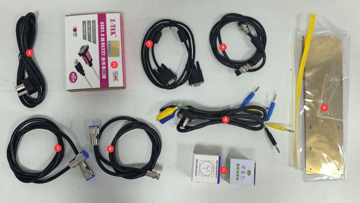
Lihat Gambar 1-1 untuk komponen lainnya.
| Jumlah | Note |
|---|---|
| ① | Kabel daya untuk EMI-9KC |
| ②③ | Kabel komunikasi RS-232 dan kabel adaptor RS-232-ke-USB, digunakan untuk menghubungkan EMI-9KC ke komputer |
| ④ | Aviation connector cable, used to connect the EMI-9KC ke LISN-C |
| ⑤⑥ | Kabel koaksial, digunakan untuk menghubungkan EMI-9KC ke LISN-C (dual N-type connectors) or the CDNE (N-type and BNC connectors) |
| ⑦ | 10A-to-16A and 16A-to-10A adapters, compatible with LISN-C |
| ⑧ | AE and EUT connection cables, used to connect to the CDNE. Packaged with the CDNE at the factory. |
| ⑨ | Copper grounding plate, used to connect to the LISN-C grounding terminal. Packaged with the LISN at the factory. |
2. Tindakan Pencegahan Keamanan
2.1 Keamanan Listrik
2.1.1 Keamanan Catu Daya
Semua peralatan harus dihubungkan ke Trafo Isolasi melalui Trafo Isolasi; sambungan langsung ke listrik utama dilarang keras untuk mencegah lonjakan daya dan risiko sengatan listrik.
The EMI-9KC Unit utama harus dihubungkan ke catu daya AC satu fasa 220 V ±10%, 50/60 Hz yang stabil; jangan gunakan perangkat jika sambungan daya longgar atau kabel rusak.
2.1.2 Keamanan Pembumian
Sistem pentanahan yang terpisah dan andal harus dipasang; semakin rendah resistansi pentanahan, semakin akurat hasil pengujiannya. Penggunaan elektroda pentanahan yang sama dengan peralatan listrik berdaya tinggi dilarang keras.
Terminal pentanahan dan pelat logam referensi dari semua peralatan harus terhubung dengan aman ke elektroda pentanahan, dan titik-titik sambungan harus bebas dari korosi dan kelonggaran.
Saat terjadi badai petir, lepaskan peralatan dari sumber daya listrik dan sambungan ground untuk mencegah kerusakan akibat sambaran petir.
2.2 Keselamatan Operasional
2.2.1 Panduan Menghidupkan/Mematikan Daya dan Menghubungkan/Memutus Sambungan
Strictly follow the sequence: “When turning on the computer, turn on the peripherals first, then the main unit; when turning off the computer, turn off the main unit first, then the peripherals.”
Before powering on or off the EUT, you must first disconnect the coaxial cable from the receiver’s front end to prevent switching transients from damaging the receiver’s internal circuitry.
Do not connect or disconnect coaxial cables or switch the L/N phase switch on the LISN during test operation, as high-voltage pulses may damage the receiver’s RF input module.
2.2.2 Batasan Sinyal Masukan
The load current for the LISN-C ke CDNE-M316 must not exceed the maximum rated current of 16 A; overloading may cause the equipment to burn out.
2.3 Keamanan Lingkungan
2.3.1 Work Environment Requirements
Suhu lingkungan pengoperasian peralatan adalah 5–35°C, dengan kelembaban relatif ≤80% dan tanpa kondensasi.
Dilarang keras menyimpan bahan yang mudah terbakar, meledak, atau korosif di dalam area pengujian, dan dilarang keras melakukan pengujian bertenaga di lingkungan yang mudah terbakar atau meledak.
Peralatan yang menghasilkan interferensi elektromagnetik yang kuat—seperti penggerak frekuensi variabel, mesin las busur, pengisi daya daya tinggi, dan pemancar nirkabel—tidak boleh ditempatkan di dalam ruang uji untuk meminimalkan dampak kebisingan latar belakang lingkungan terhadap hasil pengujian.
2.3.2 Persyaratan Lingkungan Penyimpanan dan Transportasi
Peralatan harus dikirim dalam kemasan aslinya, dengan perlindungan yang memadai terhadap guncangan, kelembapan, dan benturan. Jangan membalik kemasan atau memberikan tekanan yang berat padanya.
The ambient temperature for long-term storage should be 5–35°C, with relative humidity ≤80%, good ventilation, and no corrosive gases in the air.
2.4 Lainnya
Untuk hal-hal yang tidak tercakup dalam panduan ini, harap berhati-hati atau hubungi kami.
3. Gambaran Umum Peralatan dan Pengkabelan
3.1 EMI-9KC Penerima
3.1.1 Panel Depan
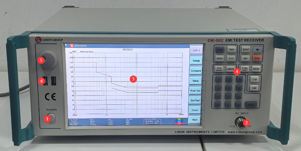
Lihat Gambar 3-1.
| Jumlah | Note |
|---|---|
| ① | Saklar daya |
| ② | Port input RF, terhubung ke LISN-C or CDNE via a coaxial cable |
| ③④⑤ | The touchscreen and on-screen control area function essentially the same as the desktop software; please refer to the software feature overview. |
| ⑥ | USB port: If a firmware update is available, you can use a USB flash drive to update it. |
3.1.2 Panel Belakang
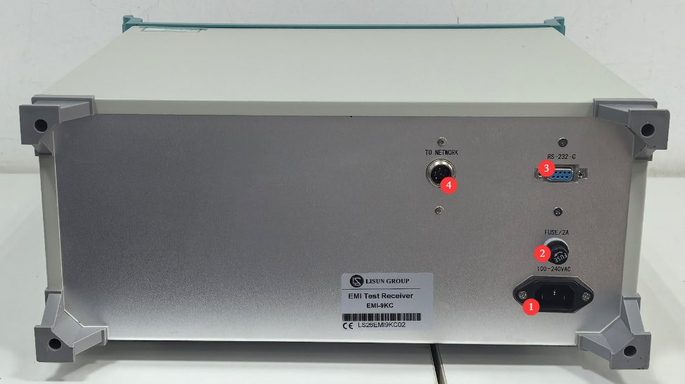
Lihat Gambar 3-2.
| Jumlah | Note |
|---|---|
| ① | Soket kabel daya, terhubung ke Transformator Isolasi |
| ② | Sekering |
| ③ | Port komunikasi RS-232: Hubungkan ke komputer menggunakan kabel komunikasi RS-232. Jika komputer tidak memiliki port RS-232, Anda dapat menggunakan kabel adaptor RS-232-ke-USB standar untuk menghubungkan ke komputer. Catatan: Jangan gunakan kabel atau adaptor komunikasi non-standar, karena hal ini dapat menyebabkan kesalahan komunikasi. |
| ④ | Aviation cable connector; connect to the LISN-C using an aviation cable |
3.2 LISN-C Jaringan Utama Buatan
3.2.1 Panel Depan
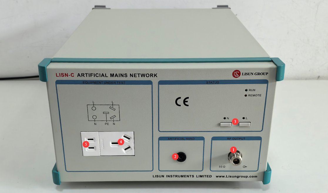
Lihat Gambar 3-3.
| Jumlah | Note |
|---|---|
| ① | Port keluaran RF; hubungkan ke EMI-9KC menggunakan adaptor N-ke-BNC dan kabel koaksial |
| ② | L/N switch, used to switch between test phase and neutral lines for interference signals |
| ③ | Antarmuka Tangan Buatan, terminal koneksi tangan simulasi, digunakan untuk menguji perangkat genggam. |
| ④ | Port koneksi kabel daya tiga kawat 16A; dapat dihubungkan langsung ke EUT atau melalui adaptor steker 16A ke 10A. |
| ⑤ | 10A two-conductor power cord connection port; can be connected directly to the EUT |
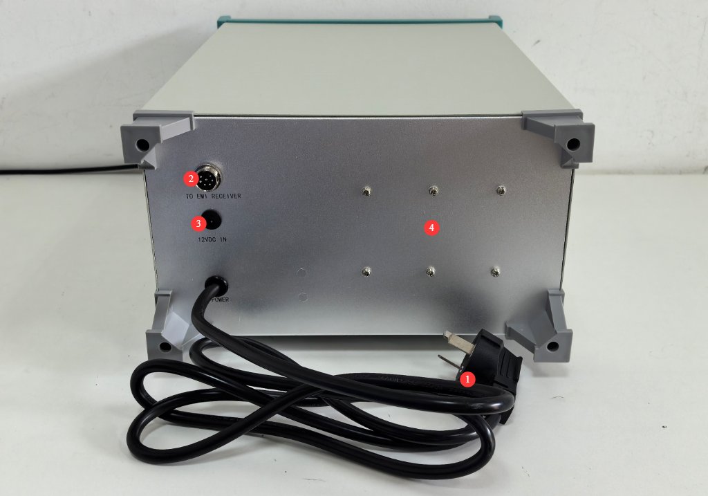
3.2.2 Panel Belakang
Lihat Gambar 3-4.
| Jumlah | Note |
|---|---|
| ① | Kabel daya dengan steker 16A; dapat dihubungkan langsung ke Trafo Isolasi atau dihubungkan ke Trafo Isolasi melalui steker adaptor 10A ke 16A. |
| ② | Aviation connector; connect to the EMI-9KC using an aviation cable |
| ③ | 12V power connector; no connection required |
| ④ | Terminal pembumian: Hubungkan menggunakan pelat pembumian tembaga sesuai dengan standar. |
3.3 Jaringan Kopling Dekopling CDNE
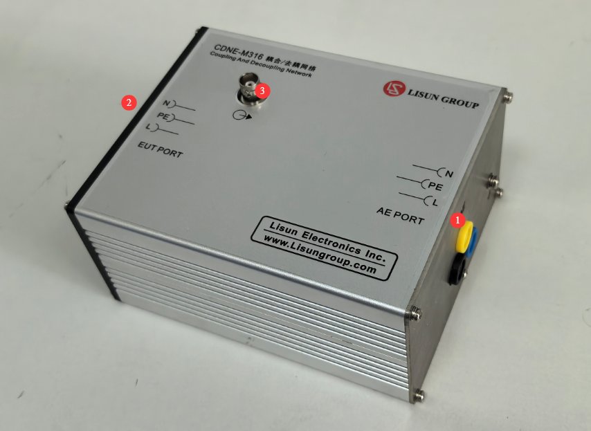
Lihat Gambar 3–5.
| Jumlah | Note |
|---|---|
| ① | PORT AE, terhubung ke Transformator Isolasi |
| ② | EUT PORT, connected to the EUT |
| ③ | Konektor keluaran RF tipe BNC, terhubung ke EMI-9KC via a coaxial cable |
3.4 Isolasi Transformator Isolasi
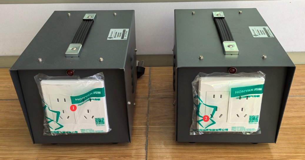
3.4.1 Panel Depan
Lihat Gambar 3–6.
| Jumlah | Note |
|---|---|
| ① | Transformator Isolasi 500VA Transformator Isolasi digunakan untuk menghubungkan EMI-9KC penerima, komputer, printer, dan perangkat lainnya. |
| ② | Transformator isolasi digunakan untuk menghubungkan LISN-C atau CDNE dan memasok daya ke EUT; ini termasuk satu stopkontak 16 A. |
3.4.2 Panel Belakang
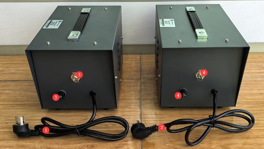
Lihat Gambar 3-7.
| Jumlah | Note |
|---|---|
| ①②. | Cukup hubungkan Trafo Isolasi ke jaringan listrik menggunakan kabel daya. Trafo Isolasi, yang memberi daya pada... EMI-9KC, harus dihubungkan ke jaringan listrik 220V; Trafo Isolasi 1kVA, yang memberi daya pada EUT, harus dihubungkan ke jaringan listrik yang sesuai berdasarkan kebutuhan EUT. |
| ③④ | Sekering |
| ⑤⑥ | Saklar daya |
4. Instalasi dan Gambaran Umum Perangkat Lunak
4.1 Instalasi Perangkat Lunak dan Driver
4.1.1 Persyaratan Operasi Sistem
Sistem Operasi: Windows 7 / Windows 8 / Windows 10 / Windows 11; Windows 10 direkomendasikan;
Persyaratan Perangkat Keras: Prosesor Pentium atau lebih tinggi, RAM ≥2 GB, ruang hard disk kosong ≥1 GB, dan setidaknya satu port USB yang tersedia;
Resolusi layar: 1024×768 atau lebih tinggi direkomendasikan.
Instalasi 4.1.2
Lihat Gambar 4-1.
| Jumlah | Note |
|---|---|
| ① | EMI-9KC Perangkat Lunak PC Penerima—Klik dua kali untuk menginstal |
| ② | Driver Adaptor RS-232 ke USB: Jika Anda menggunakan adaptor RS-232 ke USB, Anda harus menginstal driver ini. |

4.2 Pengantar Fitur Antarmuka Perangkat Lunak
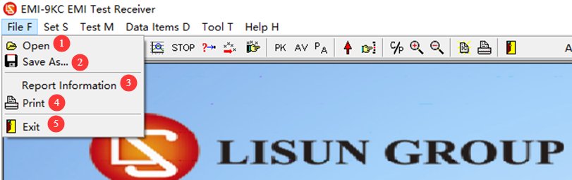
4.2.1 Menu File
Lihat Gambar 4-2.
| Jumlah | Note |
|---|---|
| ① | Buka file EMC |
| ② | Simpan hasil pengujian sebagai file emc. Catatan: file emc hanya dapat dibuka menggunakan LISUN EMI-9KC perangkat lunak. |
| ③ | Test Report Options: Enter test report information here |
| ④ | Cetak Laporan |
| ⑤ | Keluar dari Perangkat Lunak |
4.2.2 Menu Pengaturan
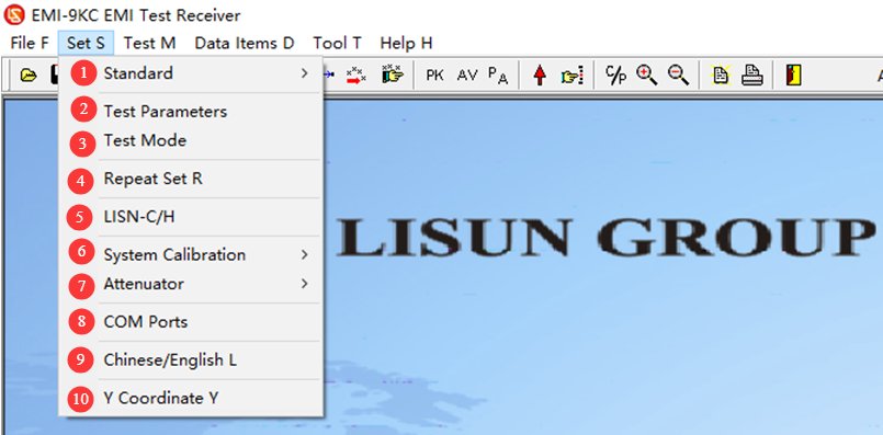
4.2.2.1 Daftar Dropdown
Lihat Gambar 4-3.
| Jumlah | Note |
|---|---|
| ① | Standar Pengujian: Pilih, Tambah, Edit, atau Hapus Standar |
| ② | For test parameters, simply use the default settings; no changes are necessary. If you have specific requirements, you may adjust them as needed. |
| ③ | Test mode; the factory default is automatic mode, so no changes are needed. If you have specific requirements, you can adjust the settings as needed. |
| ④ | Cyclic Sweep Settings |
| ⑤ | Control Artificial Mains Network. Note: This option is available only when selecting standards related to Artificial Mains Network |
| ⑥ | Kalibrasi Sistem: Digunakan oleh para insinyur profesional saat melakukan uji coba peralatan; fitur ini tidak diperlukan selama pengoperasian normal peralatan. |
| ⑦ | Attenuator: The EMI-9KC system does not come with an attenuator as standard equipment; please select “Disable” to proceed. |
| ⑧ | Communication port settings: Once the communication cable is properly connected and the driver is installed, the software will automatically detect the communication port. |
| ⑨ | Beralih antara Bahasa Mandarin dan Bahasa Inggris |
| ⑩ | Setting the Y-axis coordinate range |
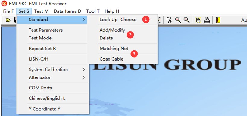
4.2.2.2 Opsi Standar Tes
Lihat Gambar 4-4.
| Jumlah | Note |
|---|---|
| ① | Kriteria Seleksi: Anda hanya dapat memilih kriteria yang telah ditambahkan sebelumnya; Anda tidak dapat mengubah parameternya. |
| ② | Tambahkan, ubah, atau hapus standar. Catatan: Harap berhati-hati; semua standar dan kurva batas ditambahkan sesuai dengan standar yang ada. Jika Anda memiliki data standar lain yang tidak termasuk dalam perangkat lunak kami, silakan kirimkan standar yang relevan kepada kami, dan kami akan menambahkannya untuk Anda. |
| ③ | Matching networks, coaxial cable corrections. Absorbing Clamp, voltage probes, CDN networks, large-loop antennas, coaxial cables, and other corrections. Note: For use only by LISUN insinyur profesional saat melakukan debugging perangkat lunak. |
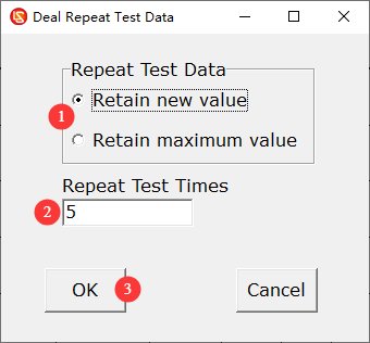
4.2.2.3 Cyclic Scan Settings
Lihat Gambar 4–5.
| Jumlah | Note |
|---|---|
| ① | You can choose to save the latest value or the maximum value. |
| ② | Jumlah pengulangan |
| ③ | Setelah Anda selesai mengkonfigurasi pengaturan, klik OK untuk menyimpannya. |
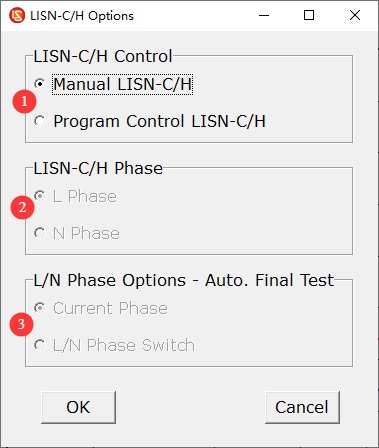
4.2.2.4 Interface with Artificial Mains Network
Lihat Gambar 4–6.
| Jumlah | Note |
|---|---|
| ① | The factory default setting is manual control, which means you must manually switch between the L and N phases on the LISN-C panel depan. |
| After selecting “Program Control,” | ② You can use the software to toggle the L/N switch on the front panel of the LISN-C. |
| ③ During automatic final testing, you can select the current phase or have the system automatically switch between L and N for the final test. |
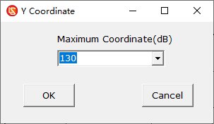
4.2.2.5 Setting the Y-axis Coordinate Range
See Figures 4–7. The default range is 0–130 dB, but you can adjust the setting as needed.
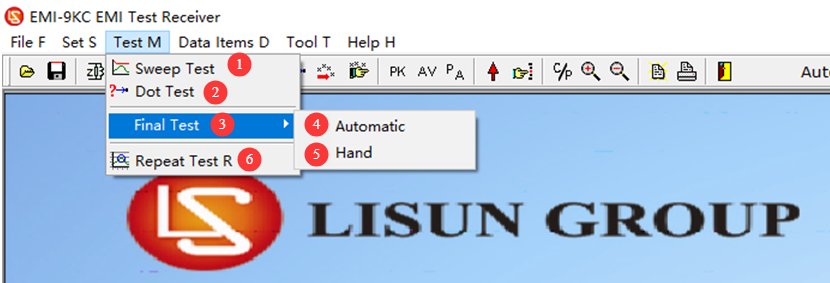
4.2.3 Menu Tes
Lihat Gambar 4–8.
| Jumlah | Note |
|---|---|
| ① | Tes Pemindaian |
| ② | Spot Test: If you only want to view data for a specific frequency, click here to manually enter the frequency and run the test. |
| ③ | Tes Akhir: Setelah tes pemindaian selesai, jika Anda ingin menguji data spesifik untuk titik-titik tertentu lagi, Anda dapat melakukan tes akhir. |
| ④ | Pengujian Akhir Otomatis: Perangkat lunak secara otomatis memilih titik frekuensi representatif berdasarkan hasil pengujian untuk pengujian akhir. |
| ⑤ | Pengujian Akhir Manual: Pengguna menambahkan titik frekuensi yang akan diuji secara manual berdasarkan kebutuhan mereka sendiri. |
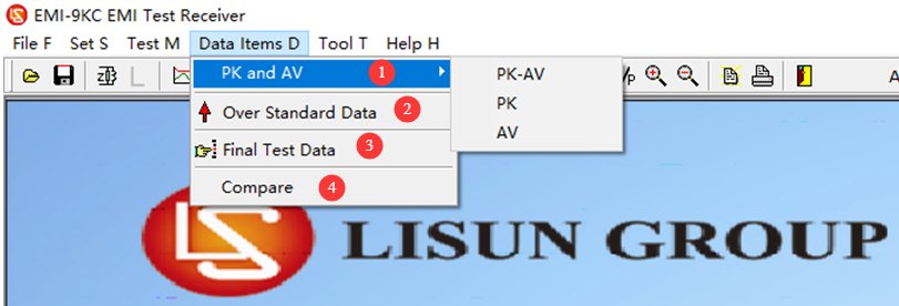
4.2.4 Menu Tampilan
Lihat Gambar 4-9.
| Jumlah | Note |
|---|---|
| ① | Grafik tersebut menunjukkan garis PK dan AV default. |
| ② | Tampilkan data yang berada di luar kurva batas. |
| ③ | Tampilkan data untuk titik uji akhir. |
| ④ | Setelah melakukan dua tes pemindaian berturut-turut, Anda dapat mengklik untuk membandingkan hasil dari kedua tes tersebut. |
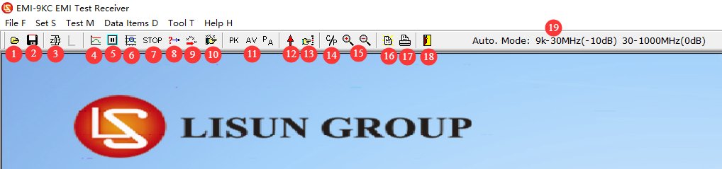
4.2.5 Pengenalan Pintasan Bilah Navigasi
Lihat Gambar 4-13.
| Jumlah | Note |
|---|---|
| ① | Buka file EMC |
| ② | Simpan sebagai file emc |
| ③ | Select this option, then click L/N to automatically toggle the L/N phase switch on the front panel of the LISN-C. Note: This option is available only when standards related to Artificial Mains Network are applied. |
| ④ | Tes Pemindaian |
| ⑤ | Pengujian Jeda |
| ⑥ | Cyclic Scan Test: Click here to perform a cyclic scan test according to the settings in Section 4.2.2.3. |
| ⑦ | Hentikan Pengujian |
| ⑧ | Pengukuran Titik |
| ⑨ | Pengujian Akhir Otomatis |
| ⑩ | Pengujian Akhir Manual |
| ⑪ | Kurva Tampilan: PK, AV, PK+AV |
| 1 | Tampilkan data yang berada di luar kurva batas. |
| ⑬ | Display data for the final test point |
| ⑭ | Tampilkan atau sembunyikan titik data yang tumpang tindih (menyembunyikan titik data yang tumpang tindih membuat kurva lebih jelas) |
| 3 | Perbesar/Perkecil: Anda dapat memperbesar kurva untuk tampilan yang lebih mudah. Setelah mengklik, gulir roda tombol tengah mouse di area tampilan kurva untuk memperbesar atau memperkecil. |
| 5 | Pengaturan Laporan Pengujian |
| ⑰ | Cetak Laporan |
| ⑱ | Keluar dari Perangkat Lunak |
| ⑲ | Menampilkan parameter modul internal perangkat; ditujukan semata-mata untuk digunakan oleh insinyur profesional selama proses debugging. |
5. Persiapan Sebelum Ujian
5.1 Persyaratan untuk Menyiapkan Lingkungan Pengujian
Prosedur Standar (Ruang Terlindung): Formal compliance testing must be conducted in a code-compliant Electromagnetic Shielding Cabinet, which completely isolates the test subject from external environmental interference, ensuring the most accurate test results. The LISUN Kabinet Pelindung Elektromagnetik seri SDR dapat digunakan untuk tujuan ini.
Pengaturan Pengujian (Ruang Standar): If no anechoic chamber is available, select a separate room with an area of at least 15 square meters that contains no other equipment emitting strong electromagnetic interference; the first floor is the optimal location, as it facilitates grounding and results in lower grounding resistance.
Area pengujian harus berjarak minimal 0.8 meter dari dinding dan benda konduktif lainnya untuk mencegah pantulan gelombang elektromagnetik memengaruhi hasil pengujian.
5.2 Diagram Tata Letak Lingkungan Pengujian Standar
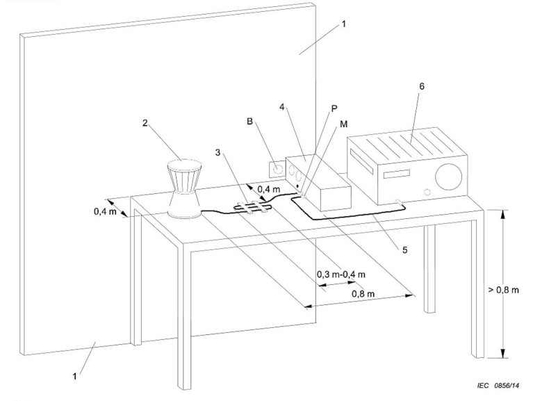
5.2.1 Test Setup for Conducted Disturbance Testing of an EUT Using a Single Cable
See Figure 5-1 (taken from CISPR-16-2-1, Figure 11).
| Jumlah | Note |
|---|---|
| ① | Dinding logam, 2 m × 2 m |
| ② | EUT |
| ③ | Kabel daya ekstra panjang yang dapat dilipat bolak-balik hingga berukuran 2 cm × 30 cm |
| ④ | LISN-C Jaringan Utama Buatan (Artificial Mains Network/AMN) |
| ⑤ | Kawat koaksial |
| ⑥ | EMI-9KC Penerima |
| B | Perhatikan titik-titik sambungan pentanahan dan gunakan pelat pentanahan tembaga untuk melakukan penyambungan. |
| M | Hubungkan LISN-C ke EMI-9KC menggunakan adaptor N-BNC dan kabel koaksial |
| P | Hubungkan kabel daya EUT ke LISN-C |
| Toleransi untuk panjang dan jarak kabel harus sedekat mungkin dengan toleransi pada aplikasi sebenarnya. | |
Depending on the specific circumstances, you may refer to other standard test layout diagrams. The following are the key points for the layout:
Peralatan meja kerja: Place on an insulated test bench 0.8 m high, with the rear of the equipment 40 cm from a grounded metal plate and ≥80 cm from other conductive objects; fold any excess length of the power cord into an S-shaped bundle 30–40 cm long; do not coil the cord;
Peralatan yang dipasang di lantai: Place the equipment on an insulating panel (12 mm thick) laid on the floor, with a grounded metal plate measuring at least 2 m × 2 m beneath the insulating panel; keep all sides of the equipment at least 50 cm from the edge of the metal plate and at least 80 cm from the LISN; fold any excess length of the power cord in the center;
Produk Pencahayaan: Lamps with built-in ballasts and separate ballasts shall be placed on insulated supports in accordance with standards; the power cord shall be 0.8 m long and laid out straight; the equipment grounding terminal shall be connected to the reference ground;
Peralatan genggam tanpa koneksi ground.: Wrap metal foil around the grip area to simulate a hand, in accordance with the standard; connect the other end of the simulated hand to the simulated hand interface on the LISN;
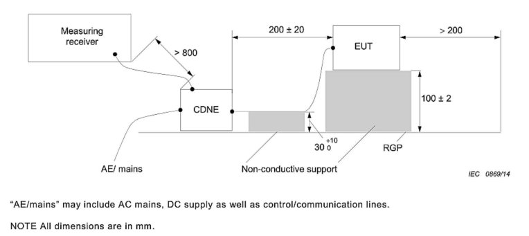
5.2.2 Pengaturan Pengujian untuk Pengujian Gangguan Radiasi pada EUT Kabel Tunggal
Lihat Gambar 5-2 (diadaptasi dari CISPR-16-2-1, Gambar 23).
Note 1: The CDNE method applies only to lighting and similar electrical equipment; standards for household appliances, IT equipment, and power tools (CISPR 14/CISPR 22) do not permit the use of CDNE as a substitute for an anechoic chamber or open-field test.
Note 2: CDNE substitute radiation testing may only be used for preliminary R& D testing and may not be used for third-party compliance certification testing.
Berikut adalah poin-poin penting untuk tugas ini:
Place an insulated wooden block 10 ± 0.2 cm high on the reference grounding metal plate, and carefully place the equipment under test on top of the block;
Perangkat yang sedang diuji dihubungkan ke port EUT CDNE melalui kabel daya sepanjang 20 ± 10 cm; kabel tersebut ditopang oleh spacer berinsulasi setinggi 4 ± 0.2 cm agar tetap sejajar dengan pelat logam;
RGP (Reference Ground Plane) adalah pelat logam pentanahan referensi di atas tanah; unit CDNE ditempatkan langsung di atas pelat logam pentanahan untuk memastikan kontak yang baik antara selubung dan pelat logam tersebut;
Port AE CDNE terhubung ke catu daya dari output Transformator Isolasi;
Refer to Figure 5-1 for the location of the EMI-9KC dan lingkungan pengujian lainnya.
5.3 Diagram pengkabelan
Lihat Gambar 5-3.
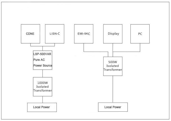
Catatan: Seri LSP terdiri dari LISUN pure sine wave regulated power supplies, designed to provide a stable, pure sine wave AC power supply to the EUT; these are available for optional purchase.
6. Prosedur Pengujian Kekebalan Tubuh yang Dilakukan dan Dipancarkan
6.1 Persiapan
Lihat Bab 3 dan 5 untuk menyiapkan lingkungan pengujian dan menghubungkan semua peralatan sistem dan EUT.
6.2 Pemanasan di Startup
Refer to Section 2.2.1. Power on all equipment and the EUT in the correct sequence and following the proper procedures, ensuring that the EUT is in its normal operating state. As required by the standard, the EUT must be allowed to warm up to a stable operating state (typically 15 to 30 minutes) before testing.
6.3 Konfirmasi Parameter Uji
6.3.1 Pemilihan Standar
Select the appropriate standard. For example, if you are using the LISN-C to test for conducted emissions, select EN 55015; if you are using the CDNE-M316 to test for radiated emissions, select EN 55015 CDNE-M3.
6.3.2 Pengaturan Attenuator
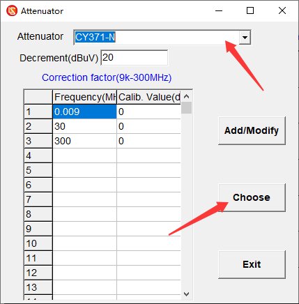
The EMI-9KC does not come with an attenuator as standard; simply select the option to disable the attenuator. If you purchase and use an external attenuator, you must select the correct attenuator parameters; see Figure 6-1 for the settings.
6.4 Tes Pemindaian
6.4.1 Pengalihan Fase L/N pada LISN-C
Both the L phase and the N phase must undergo conducted emission testing. After testing one phase, you can switch the LISN-C’s L/N phase switch manually or via software to test the other phase. Note: Do not switch the L/N phase switch during testing.
6.4.2 Antarmuka TANGAN BUATAN LISN-C
When testing Class I and Class II ungrounded handheld power tools (handheld drills, angle grinders, electric saws, grinders, etc.), ungrounded handheld small household appliances (handheld hair dryers, handheld vacuum cleaners, handheld food processors, etc.), and handheld medical electrical equipment (dental handpieces, handheld physical therapy devices, in accordance with IEC 60601-1-2), this must be used.
Copper wire and 0.05 mm thick copper foil must be used to connect the LISN-CAntarmuka TANGAN BUATAN ke pegangan dan wadah EUT untuk menerapkan kopling simulasi tubuh manusia.
6.4.3 Tes Pemindaian Umum
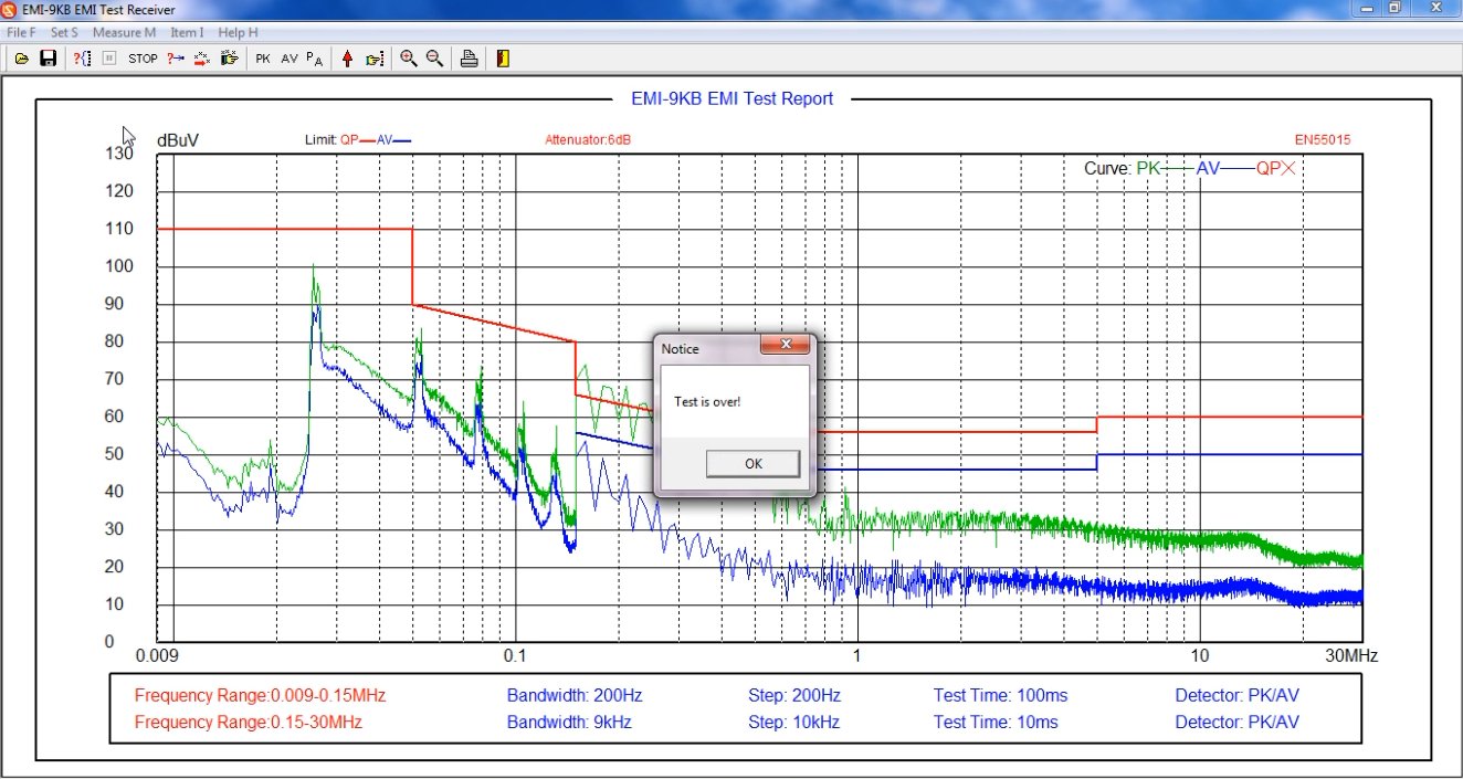
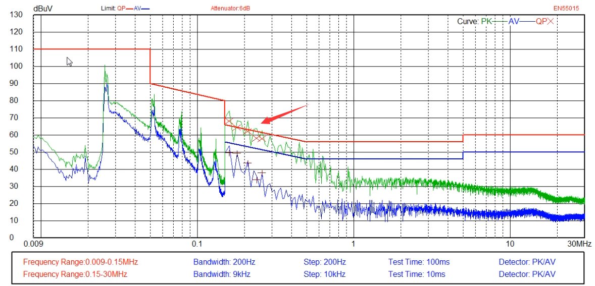
Click “Scan Test” (or “Loop Scan Test”), wait for the scan to complete. If an error occurs, click “Stop Test,” make the necessary adjustments, and then restart the test. Once the scan is complete, see Figure 6-2.
Garis merah: Garis batas quasi-peak (QP);
Garis biru: Garis batas rata-rata (AV);
Kurva hijau: Kurva uji puncak (PK);
Kurva biru: Kurva uji rata-rata (AV).
6.5 Ujian Akhir
If the average values (AV) of the test results are all below the limit curve, and the peak values (PK) are all below the quasi-peak (QP) limit curve, then the EUT meets the standard requirements, because the actual quasi-peak (QP) value measured during testing will not exceed the peak (PK) value. If the tested peak value (PK) exceeds the quasi-peak (QP) limit curve, the EUT is not necessarily non-compliant with the standard; a final test is required.
6.5.1 Pengujian Akhir Otomatis
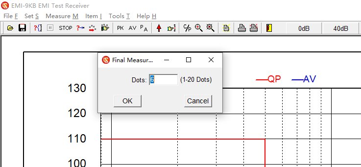
Masukkan jumlah titik frekuensi yang akan diuji, dan perangkat lunak akan secara otomatis memilih titik frekuensi berdasarkan kurva uji untuk melakukan pengujian akhir, seperti yang ditunjukkan pada Gambar 6-3.
6.5.2 Pengujian Akhir Manual
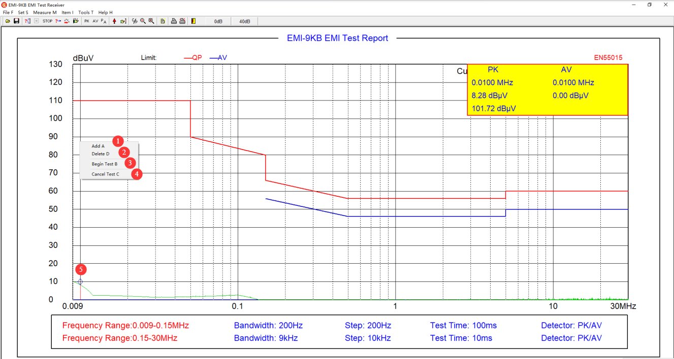
Di area kurva uji perangkat lunak, klik kanan pada titik di mana pengujian akhir akan dilakukan, seperti yang ditunjukkan pada Gambar 6-4.
| Jumlah | Note |
|---|---|
| ① | Tambahkan Endpoint |
| ② | Hapus Titik Akhir |
| ③ | Setelah menambahkan semua poin pengujian akhir yang diperlukan, klik “Mulai Pengujian Akhir.” |
| ④ | Jika Anda tidak lagi ingin berpartisipasi dalam ujian akhir, klik “Batalkan Ujian Akhir.” |
| ⑤ | Berlian biru menunjukkan lokasi titik uji akhir yang ditambahkan. |
6.5.3 Interpretasi Data Uji Akhir
See Figure 6-5. The red X marks the quasi-peak (QP) values from the final test. If all quasi-peak (QP) values from the final test fall below the quasi-peak (QP) limit curve, the EUT meets the standard requirements. Otherwise, it does not meet the standard requirements.
6.6 Point Measurement
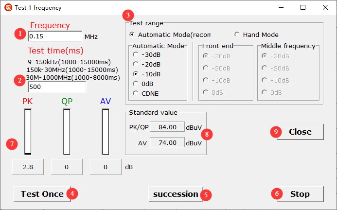
Lihat Gambar 6-6.
| Jumlah | Note |
|---|---|
| ① | Enter the frequency points you want to test |
| ② | Test duration: You can set it according to the prompts. |
| ③ | Test range: Unless otherwise specified, simply select “Auto” mode. |
| ④ | Perform a single test |
| ⑤ | Conduct continuous testing |
| ⑥ | Hentikan Pengujian |
| ⑦ | Display test results: PK, QP, and AV values |
| ⑧ | Displays the limit value for that frequency point under the currently selected standard. |
| ⑨ | Close the Point Measurement Interface |
6.6 Simpan dan Cetak Laporan Tes
Lihat Bagian 4.2.1 untuk menyimpan atau mencetak laporan pengujian.
6.7 Procedure for Shutting Down the System at the End of a Test
Ensure the equipment is in the “Test Stop” state → Disconnect the coaxial cable on the LISN/CDNE side → Turn off the EUT’s power → Turn off the receiver and computer → Turn off Isolation Transformer.
7. Pemeliharaan dan Perawatan Peralatan Harian
7.1 Routine Use and Maintenance
7.1.1 Pemeliharaan Bagian Luar dan Antarmuka
After each use, wipe the surface of the equipment with a dry, soft cloth to remove dust. Do not use highly corrosive organic solvents such as gasoline, acetone, or thinners. To clean stubborn stains, use a lint-free cloth dipped in a small amount of anhydrous ethanol to wipe the area quickly, then dry it immediately afterward.
Inspect the BNC connectors, power connectors, and terminal blocks monthly; remove any oxidation to ensure good contact; and cover the connectors with protective caps when not in use to prevent dust from entering.
Each piece of equipment is assigned to a specific user; unauthorized personnel are prohibited from operating it. Do not disassemble the equipment casing without the manufacturer’s authorization; any hardware damage resulting from unauthorized disassembly is not covered under the free warranty.
7.1.2 Pemeliharaan Kabel dan Aksesoris
Hindari menekuk kabel koaksial secara tajam, menginjaknya, atau memberinya tekanan dari benda berat. Saat menyimpannya, gulung kabel secara longgar untuk mencegah konduktor internal putus.
Tangani aksesori presisi seperti attenuator dan konektor dengan hati-hati untuk mencegah kerusakan internal akibat terjatuh.
Pengaturan perangkat lunak tidak boleh diubah secara sembarangan, dan standar bawaan serta data kalibrasi tidak boleh diubah tanpa izin.
7.2 Spesifikasi Penyimpanan
7.2.1 Persyaratan Lingkungan Penyimpanan
Suhu: 5°C hingga 35°C; relative humidity: ≤65% RH; dry, dust-free environment free of corrosive gases.
7.2.2 Operasi Penyimpanan Jangka Panjang
Matikan daya dan cabut semua kabel; bersihkan peralatan dan bungkus dengan plastik anti debu; hidupkan daya selama 30 menit setiap bulan untuk mencegah kerusakan akibat kelembapan pada komponen.
7.3 Persyaratan Interval Kalibrasi
Untuk memastikan akurasi pengukuran dan keandalan operasional peralatan, disarankan agar peralatan tersebut secara berkala dikirim ke laboratorium metrologi pihak ketiga yang berkualifikasi untuk kalibrasi. Interval kalibrasi yang disarankan adalah 12 bulan. Pengguna dapat menentukan interval kalibrasi spesifik berdasarkan frekuensi penggunaan, kondisi lingkungan, dan persyaratan sistem mutu.
8. Pemecahan Masalah dan Penyelesaian Masalah Umum
| Gejala Kesalahan | Prosedur |
|---|---|
| Berbagai pesan kesalahan mungkin muncul saat menggunakan perangkat lunak, seperti perangkat lunak gagal terbuka atau kesalahan yang terjadi selama pemindaian. | Pastikan Anda masuk ke komputer menggunakan akun administrator, dan pastikan perangkat lunak tersebut berjalan dengan hak akses administrator. |
| Perangkat lunak berfungsi normal selama uji pemindaian, tetapi macet selama uji akhir. | Tes terakhir memiliki persyaratan komunikasi yang lebih ketat daripada tes pemindaian. Pastikan Anda hanya menggunakan kabel komunikasi asli kami dan bukan kabel komunikasi atau kabel ekstensi lainnya; pastikan Anda menggunakan port komunikasi di bagian belakang komputer desktop (port USB pada laptop dan port di bagian depan komputer desktop biasanya tidak menyediakan daya yang cukup, yang dapat memengaruhi komunikasi); jika masih tidak berhasil, silakan coba menambahkan kabel tambahan. RS232 port komunikasi ke komputer Anda dan hanya gunakan RS232 kabel komunikasi—jangan gunakan RS232adaptor -ke-USB untuk komunikasi |
| Hasil tes umumnya lebih rendah atau lebih tinggi dari yang diharapkan. | Harap verifikasi bahwa pengaturan attenuator perangkat lunak sesuai dengan kondisi sebenarnya. |
| Hasil pengujian selalu mendekati kebisingan latar belakang, dan penerima EMI tidak dapat mendeteksi sinyal apa pun. | Periksa sambungan kabel koaksial; ganti kabel koaksial dan coba lagi. |
| Tingkat kebisingan latar belakang yang terlalu tinggi dan fluktuasi yang signifikan pada data uji. | Verify that all equipment in the system uses Isolation Transformer; optimize the grounding system to reduce grounding resistance; turn off other electrical equipment in the laboratory or conduct testing inside a shielded room. |