
 Inggris
 中文简体
中文简体 Русский
 Español
 Português
 Türkçe
 العربية
 Deutsch
 Polski
 Italiano
 Français
 한국어
한국어 ไทย
ไทย Tiếng Việt
 日本語
日本語





























Pengukuran Kekebalan EFT
Pengguna manual
berlaku LISUN models: EFT-CLAMP、EFT-DESK、EFT61000-4,EFT61000-4-100A、EFT61000-4-32A、EFT61000-4A、EFT61000-4A-100A、EFT61000-4A-32A
1. Membuka Kemasan dan Mengenal Peralatan Secara Dasar
1.1 Spesifikasi Teknis Utama
| LISUN Pilih Model | EFT61000-4 | EFT61000-4A | EFT61000-4-32A | EFT61000-4A-32A | EFT61000-4-100A | EFT61000-4A-100A |
| Tegangan Output | 0–5 meter persegi | 0–6 meter persegi | 0–5 meter persegi | 0–6 meter persegi | 0–5 meter persegi | 0–6 meter persegi |
| Frekuensi Pulsa | 0.1 kHz to 1200 kHz, continuously adjustable | |||||
| Polaritas denyut nadi | Positive/Negative, Automatic Alternation Between Positive and Negative | |||||
| Perlawanan internal | 50 Ω ±20%, 1000 Ω ±20% | |||||
| Waktu Naik Pulsa | 5ns ±30% | |||||
| Pulse Width (at 50 Ω) | 50ns ±30% | |||||
| Pulse Width (at 1 kΩ) | 35 ns hingga 150 ns | |||||
| Periode Kereta Pulsa | 1 ms sampai 1000 ms | |||||
| Number of Pulse Strings | 1-255 | |||||
| Waktu Tes | 1 s–9999 s | |||||
| Fitur Pengujian | Set the test mode or IEC class as desired | |||||
| Coupling dan Decoupling Network | Built-in 16A, 3 fase/5 kawat | Built-in 32A, 3 fase/5 kawat | Eksternal 100A, 3 fase/5 kawat | |||
| Sumber Daya listrik | AC 220 V (110 V optional) ±10%, 50/60 Hz | |||||
1.2 Pemeriksaan dan Verifikasi Aksesori Saat Membuka Kemasan
1.2.1 Membuka Kemasan dan Pemeriksaan Visual
Saat membuka kemasan perangkat, tangani dengan hati-hati untuk menghindari goresan pada casing dengan alat tajam. Setelah membuka kemasan, periksa terlebih dahulu bagian luar perangkat untuk memastikan tidak ada deformasi atau penyok yang terlihat, dan tombol-tombolnya tidak rusak atau longgar.
Jika Anda melihat adanya kerusakan atau perubahan bentuk pada peralatan atau aksesori, jangan nyalakan daya. Segera hubungi kami.
1.2.2 Komputer Host dan Aksesoris
Main Units: ① EFT61000-4 EFT Immunity Measurement; ② EFT-DESK Standard Test Bench; ③ EFT-CLAMP Capacitive Coupling Clamp.
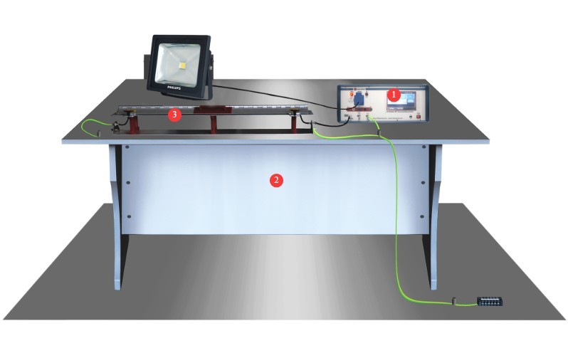
Gambar 1
Note: Items ② and ③ are optional.
The EFT-CLAMP Capacitive Coupling Clamp is used to test I/O lines.
Standard Accessories: ① Power cord; ② or ③ EUT power input cable (choose one);④ EUT power output, used to connect the EUT to the instrument’s front panel; ⑤ coaxial cable, used to connect to an external oscilloscope for waveform monitoring; ⑥ ground wire, used to connect to the PGND protective ground terminal; ⑦ discharge tube, used to check whether the instrument produces a pulse output in the event of a device malfunction.
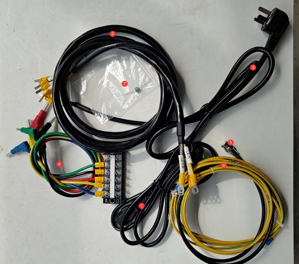
Gambar 2
Tautan unduhan untuk manual pengguna digital, kartu garansi, dan dokumen lainnya telah dikirimkan kepada Anda melalui email. Silakan unduh sesegera mungkin. Jika Anda melewatkan email tersebut, jangan ragu untuk menghubungi kami untuk meminta tautan unduhan lagi.
2. Tindakan Pencegahan Keamanan
2.1 Pedoman Penempatan
Letakkan di permukaan kerja yang stabil; hindari memiringkan atau membalikkannya, dan jauhkan dari sumber getaran;
The equipment must be placed at least 1000 mm away from walls and surrounding structures (such as other testing equipment and shelving) to facilitate maintenance; at least 2000 mm of space must be left in front of the equipment to ensure smooth operation, and there must be no obstructions in the surrounding area.
2.2 Standar Keselamatan Tegangan Tinggi
2.2.1 Pemeriksaan Keamanan
Pastikan catu daya kompatibel dengan peralatan, pastikan catu daya terhubung ke ground dengan benar, dan periksa apakah kabel ground tidak rusak atau longgar;
Grounding Requirements: The host unit’s protective grounding terminal (PGND) must be connected to the ground reference plane; the grounding resistance must be ≤4 Ω; the grounding cable must be securely connected, with no looseness or breaks;
The ground reference plane must be connected to the grounding metal plate and to the ground; all ground connections must have low impedance to prevent potential differences from occurring during discharge.
2.2.2 Persyaratan Keselamatan untuk Prosedur Operasional
Operators must undergo professional training and be familiar with this manual and the relevant standards. Non-professionals are prohibited from operating or disassembling the equipment. The equipment contains high-voltage circuits; opening the cover may pose an electric shock hazard. Contact the manufacturer’s technical staff for repairs;
Once the equipment is powered on, do not touch the terminal blocks, cables, or the EUT;
Operators should ensure their hands are dry and free of metal jewelry; it is recommended that they wear insulated gloves while working;
Selama pengujian, personel yang tidak berwenang dilarang berada dalam jarak 1 meter dari EUT untuk mencegah sengatan listrik yang tidak disengaja atau gangguan dari pelepasan listrik;
Before replacing the electrodes, you must first ensure that the high-voltage output has been turned off (the HV indicator light is off) and wait at least 5 minutes to ensure that the internal high-voltage capacitor is completely discharged;
Jangan makan atau minum selama pengujian untuk mencegah kecelakaan akibat sengatan listrik;
Jika melibatkan beberapa orang, tetapkan peran dan tanggung jawab dengan jelas, dan konfirmasikan satu sama lain sebelum memulai pengujian untuk menghindari kesalahan.
2.3 Lainnya
Untuk hal-hal yang tidak tercakup dalam panduan ini, harap berhati-hati atau hubungi kami.
3. Persiapan Sebelum Ujian
3.1 Test Environment and Wiring for Power Cord Immunity Testing
3.1.1 Front of the Instrument
① Grounded metal plate, connected to ground via a conductor; ② Wooden test bench; ③ Grounded reference plane, connected to the grounded metal plate via a ground wire;④ Can be connected to the EUT; ⑤ Can be connected to the EUT; ⑥ Connect the protective ground terminal of the SGND signal line on the front panel of the instrument to the reference ground plane; ⑦ Insulated support; ⑧ EUT test specimen.
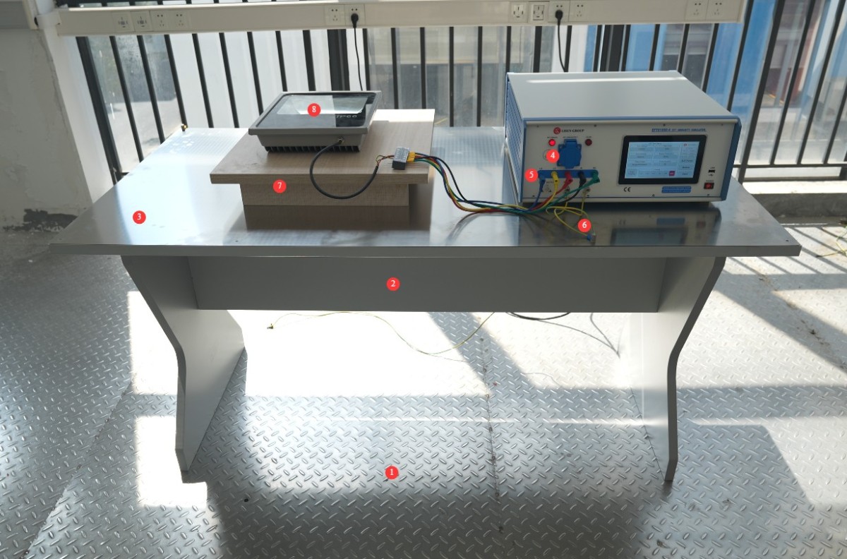
Gambar 3
The grounding reference plane must meet the following dimensions: thickness ≥ 0.25 mm; it must be large enough to accommodate the EUT, instruments, coupling devices, and all accessories; and it must extend 10 cm beyond the edges on all four sides.
The EUT must be placed on the grounded reference plane using an insulating support with a thickness of 10 cm, and the distance between the bottom of the EUT and the grounded reference plane must be strictly maintained at 10 cm.
The instrument (including the coupling network) shall be placed directly on the grounded reference plane, at a distance of ≥0.5 m from the EUT; the EUT shall be located at a distance of ≥0.5 m from conductive structures such as laboratory walls and anechoic chamber walls.
The length of the power and signal cables connecting the EUT to the test equipment shall be maintained at 0.5 m ± 0.05 m; if the EUT has a built-in, non-detachable cable longer than 0.5 m, the excess length shall be folded (avoiding the formation of a flat loop) and placed 10 cm above the ground reference plane.
3.1.2 Back of the Instrument
① Power cord; ② EUT power input cable—please connect the EUT to a suitable power source; ③ PGND protective ground terminal—please connect to a grounded metal plate.
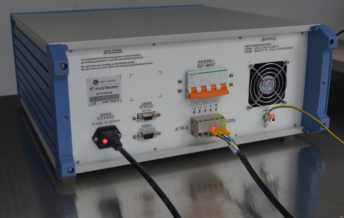
Gambar 4
3.2 Test Environment and Wiring for IO Signal Line Immunity Testing
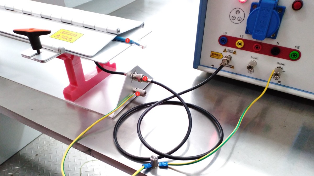
Place the Capacitive Coupling Clamp on the ground reference plane. ① Connect the ground terminal of the Capacitive Coupling Clamp to the ground reference plane; ② Connect the Capacitive Coupling Clamp to the BNC connector on the instrument’s front panel via a coaxial cable; ③ Route the I/O cable through the Capacitive Coupling Clamp.
Gambar 5
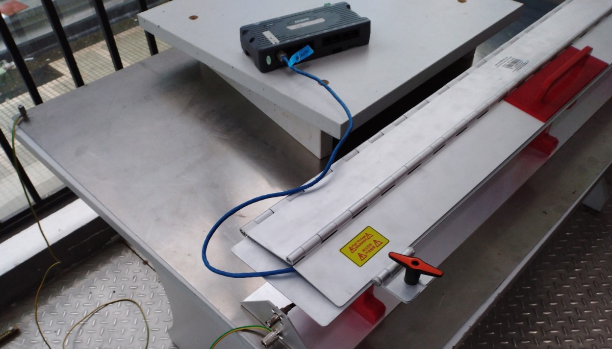
Route the EUT’s I/O cables through the capacitive coupling clamp, with one end of each cable connected to the EUT and the other to the AE (auxiliary) device. Place the EUT and the AE device on 10-cm-thick insulated supports, respectively.
Gambar 6
The distance between the AE equipment and the EUT must be ≥0.5 m, and its power cord must be connected to the power supply network via a decoupling network to prevent impulse interference from being conducted to auxiliary equipment.
3.3 Konfirmasi Parameter Uji
| Nama Parameter | Rentang pengaturan | Standard Requirements (GB/T 17626.4-2018) |
| Tegangan uji | 0.25–5/6 kV (open circuit) | Power Ports: Levels 1–4 (1 kV/2 kV/4 kV/6 kV); I/O Ports: 1 and 2 corresponding to the power ports |
| Waktu Tes | 1–9999 detik | The standard test duration is 60 seconds; custom durations are available upon request. |
| Periode Kereta Pulsa | 1–1000 mdtk | The default value is 300 ms, but it can be modified according to the test plan. |
| Frekuensi pengulangan pulsa | 0.1–1200 kHz | Commonly used frequencies: 5 kHz, 100 kHz, 300 kHz |
| Sudut fase | 0–359°/Asynchronous | If there are no synchronization requirements, select “Asynchronous.” |
| Jumlah Pulsa | 1-255 | The default is 75. The string length is calculated as (number of items – 1) / frequency of repetition. |
| Polaritas denyut nadi | Positive/Negative/Alternating Positive and Negative | For routine testing, select “Alternating Positive and Negative” to cover all interference scenarios. |
3.4 Pemanasan Peralatan dan Uji Mandiri
Turn on the power switch on the front panel of the host; the device enters standby mode, the power indicator lights up, and the cooling fan starts.
Tunggu 5 menit agar perangkat memanas, dan periksa apakah layar sentuh menampilkan gambar dengan normal dan tidak ada pesan kesalahan.
4. Pengantar Program Layar Sentuh
4.1 Layar Awal
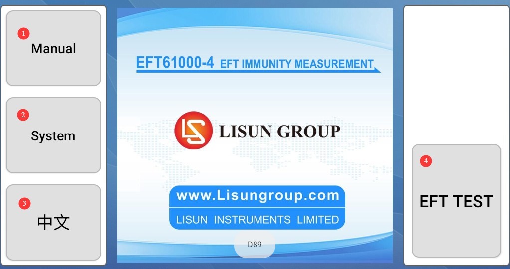
① General Usage Notes (Features are still being developed; no action is required at this time); ② System Information Screen; ③ Switch Between Chinese and English; ④ EFT Test Screen.
Gambar 7
4.2 System Information Screen
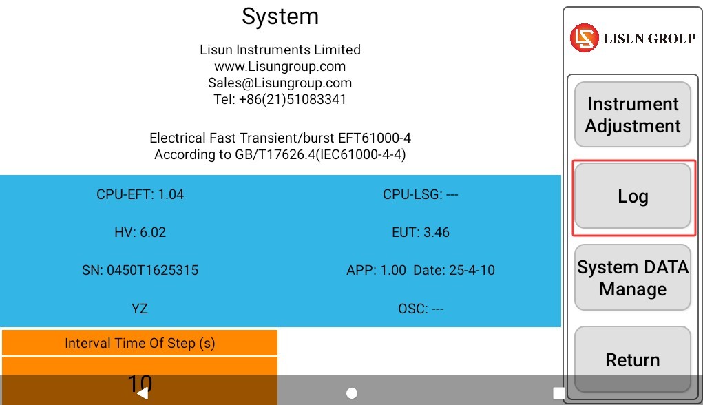
Test Logs: View or export historical test logs.
Gambar 8
4.3 EFT Test Interface
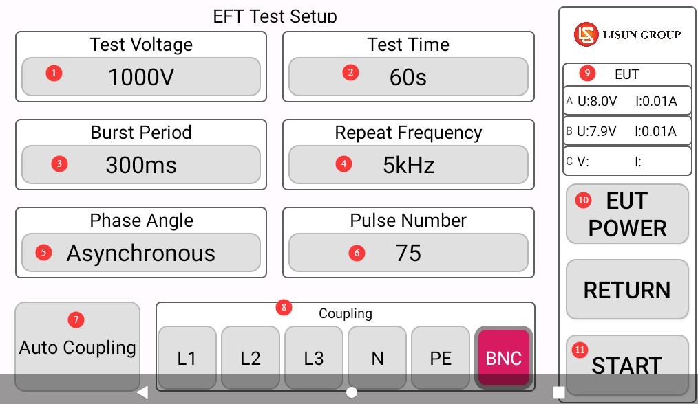
① Test voltage and polarity settings; ② Test duration settings; ③ Pulse train period settings; ④ Pulse repetition frequency settings; ⑤ Phase angle settings; ⑥ Number of pulses settings; ⑦ Automatic coupling option, allowing you to select the required coupling lines all at once;⑧ Manual selection of coupling lines; single or multiple selections are possible; ⑨ Display of the EUT’s current electrical parameters; ⑩ Click to turn the EUT power on or off; ⑪ Click to start or stop the test.
Gambar 9
Note: Power port coupling: Select any combination of “L1,” “L2,” “L3,” “N,” and “PE”; Signal port coupling: Select “BNC”; Automatic coupling: Applies interference in the system’s preset order (L1 → L2 → L3 → N → PE → combination), suitable for comprehensive testing.
5. Fast Transient and Burst (FTB) Test
5.1 Prosedur Operasional
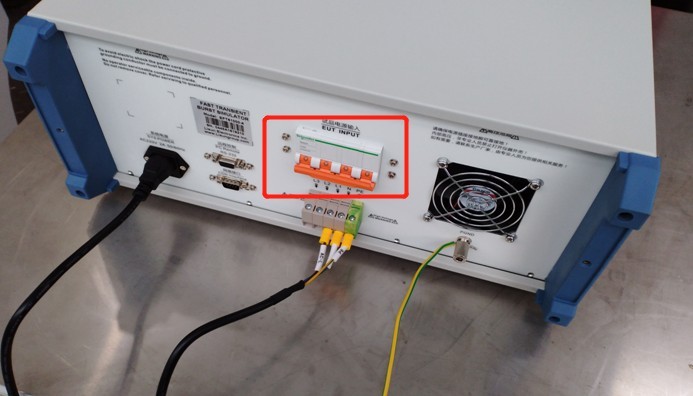
If the EUT requires power, close the EUT power input switch on the back of the device.
Gambar 10
Set all test parameters according to sections 3.3 and 4.3.
Click “EUT POWER” to turn on the EUT power supply.
Click “START” to begin the test.
5.2 Menentukan Apakah EUT Telah Lulus Uji
| Criteria Levels | Definition of Standards | Penjelasan Sederhana | Pernyataan Kepatuhan |
| Category A (Highest Requirements) | Performs normally within the limits specified by the manufacturer, the client, or the purchaser | During and after the test, the EUT’s functionality and performance were completely unaffected, with no abnormalities observed. | Fully meets the requirements; passed the test |
| Kategori B | Kehilangan atau penurunan fungsi atau kinerja sementara yang akan pulih dengan sendirinya setelah gangguan berhenti, tanpa memerlukan intervensi operator. | Temporary malfunctions (such as stuttering or brief data loss) may occur during the test, but normal operation will resume immediately after the pulse stops. | Generally considered acceptable and suitable for most non-critical equipment |
| Kategori C | A temporary loss or reduction in functionality or performance that requires operator intervention to restore (e.g., restart, reset, reconfiguration) | After the test, the EUT was unable to return to normal on its own and required manual intervention to restore functionality. | This is generally considered nonconforming, unless otherwise specified in the product standard. |
| Kategori D | Irreversible loss of functionality or reduced performance due to hardware or software damage, or data loss | The EUT has suffered a permanent failure, such as hardware damage, a software crash, or the loss of critical data that cannot be recovered. | Completely unsatisfactory; test failed |
6. Prosedur Pasca-Ujian
6.1 Tes Dihentikan
If the EUT is visibly damaged during the test, immediately tap “Stop Test” on the touchscreen, then tap “EUT Power” to turn off the EUT’s power.
If no abnormalities occur during the test, wait for the pulse test to complete automatically, then click “EUT Power” to turn off the EUT’s power.
Turn off the EUT input power supply switch on the back of the unit.
Wait 5 minutes to ensure that the high-voltage capacitors inside the host unit have fully discharged, then replace the EUT for testing, or turn off the host unit’s power.
6.2 Pembersihan dan Penataan Pasca-Pengujian
Bersihkan area pengujian dan lap dengan kain kering; jangan gunakan alkohol atau bahan pembersih korosif.
Pulse testing is a destructive test; it does not automatically generate a test report, but the device automatically saves the test data. You can go to “System Information,” click “Test Log,” and export the corresponding test data to a USB flash drive via the USB port. The exported file is in TXT text format.
6.3 Penyimpanan Peralatan
6.3.1 Persyaratan Penyimpanan Jangka Pendek
Jika peralatan tersebut digunakan setiap hari, tidak diperlukan tindakan lebih lanjut setelah setiap pengujian selesai dan peralatan telah dibersihkan.
6.3.2 Persyaratan Penyimpanan Jangka Panjang
Jika perangkat tidak akan digunakan dalam jangka waktu lama (lebih dari satu bulan), harap lepaskan semua kabel dan tutupi perangkat dengan penutup debu untuk mencegah penumpukan debu.
Perangkat ini sebaiknya dinyalakan sekali sebulan selama setengah jam saja untuk mencegah penuaan komponen listrik (seperti kapasitor dan kontaktor).
7. Pemecahan Masalah dan Penyelesaian Masalah Umum
7.1 Perangkat tidak mau menyala
Gejala: Setelah menyalakan sakelar daya, perangkat tidak merespons (lampu indikator tidak menyala, dan kipas tidak berputar).
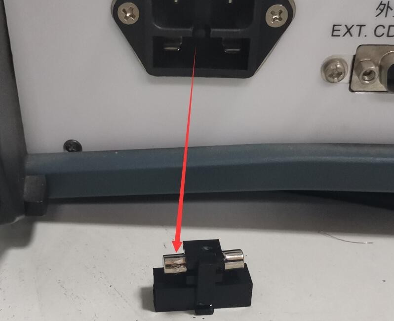
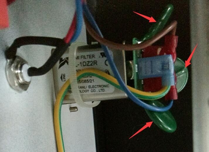
Kemungkinan penyebabnya: ① Kabel daya tidak terhubung dengan benar atau rusak; ② Tegangan suplai tidak normal; ③ Sekring putus; ④ Varistor (MOV) terbakar.
Solution: Ensure the power cord is intact and securely connected. Power supply issues—such as unstable voltage, excessively high voltage, or harmonic interference—can cause the fuse or varistor to burn out. We recommend using a regulated, clean sine-wave AC power supply to power the device. Replace the fuse or varistor with one of the same type.
Gambar di bawah ini menunjukkan lokasi sekering:
Gambar 39
Gambar berikut menunjukkan lokasi varistor (MOV) di dalam catu daya yang telah difilter:
Gambar 40
7.2 Restart Perangkat Otomatis
Symptom: The device automatically restarts during pulse output.
Kemungkinan penyebab: Kabel ground tidak terhubung dengan benar.
Solution: Refer to Section 2.2.1. Connect the PGND grounding terminal on the back of the host to ground, and ensure that the grounding resistance is ≤4Ω. Otherwise, high voltage may not be safely dissipated, causing the device to automatically restart.
7.3 Pulse Phase Angle Test Failed
Symptom: The synchronization phase angle has been set, but the pulse test is not being performed according to the corresponding phase angle.
Kemungkinan penyebab: Catu daya EUT tidak dinyalakan.
Procedure: The EUT must be powered by an AC source, and the EUT must be turned on during testing so that the pulse generator can detect the EUT’s power supply waveform and perform pulse testing according to the set phase angle.