
 Inggris
 中文简体
中文简体 Русский
 Español
 Português
 Türkçe
 العربية
 Deutsch
 Polski
 Italiano
 Français
 한국어
한국어 ไทย
ไทย Tiếng Việt
 日本語
日本語





























Generator Pulsa Lonjakan Tegangan
Pengguna manual
berlaku LISUN Model: DO160-S17
1. Membuka Kemasan dan Mengenal Peralatan Secara Dasar
1.1 Spesifikasi Teknis Utama
| Parameter Teknis | Note |
| Rentang Tegangan Uji | 5 V–1000 V (continuously adjustable) |
| Bangun Waktu | ≤2 mikrodetik |
| Durasi | >10 μs |
| impedansi | 50 ± 10% |
| Keluaran Polaritas | Positif negatif |
| Pelatuk | secara otomatis |
| Frekuensi Pulsa | Hingga 2 Hz |
| Jaringan Decoupling Kopling | AC/DC 440 V/16 A |
1.2 Membuka Kemasan dan Memeriksa Isinya
1.2.1 Membuka Kemasan dan Pemeriksaan Visual
When unpacking the device, handle it gently to avoid scratching the outer casing with sharp tools. After unpacking, first inspect the exterior of the device to ensure there are no visible deformations or dents, and that the buttons are not damaged or loose. If you notice any abnormalities with the device or its accessories, do not turn it on. Please contact us immediately.
1.2.2 Unit Utama dan Aksesoris
Host Category: DO160-S17 Voltage Spike Pulse Generator.
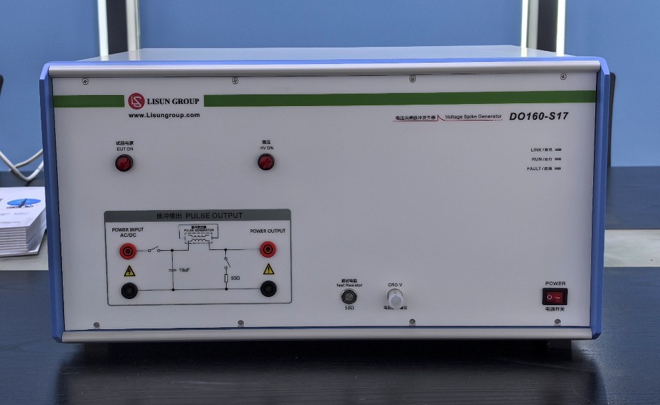
Gambar 1
Aksesoris standar:
| Jumlah | Note |
| ① | EUT Power Cord and EUT Connection Cable |
| ② | Coaxial cable, used to connect an external oscilloscope for waveform monitoring |
| ③ | PAD, with a pre-installed app for controlling the DO160-S17 |
| ④ | Kabel ground, digunakan untuk menghubungkan ke terminal ground pelindung PGND. |
| ⑤ | Kabel Listrik |
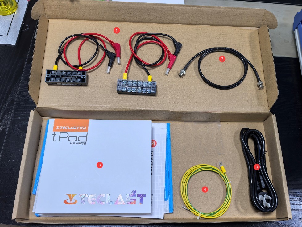
Gambar 2
Download links for the electronic user manual, warranty card, and other documents will be sent via email. Please download them promptly. If you miss the email, you may contact us to request the download links again.
2. Tindakan Pencegahan Keamanan
2.1 Pedoman Penempatan
Ensure the ambient temperature is between 15°C and 35°C, relative humidity between 10% and 60% (no condensation), and atmospheric pressure between 86 kPa and 106 kPa to prevent high-voltage short circuits or damage to the equipment caused by moisture;
The premises must be free of strong electromagnetic interference, corrosive gases, flammable or explosive materials, and dust, and must be well-ventilated to prevent sparks from causing hazards;
Letakkan di permukaan kerja yang stabil; hindari memiringkan atau membalikkannya, dan jauhkan dari sumber getaran;
The equipment must be placed at least 1 meter away from walls and surrounding structures (such as other testing equipment and shelves) to facilitate maintenance; at least 2 meters of space must be left in front of the equipment to ensure smooth operation, and there must be no obstructions around it.
2.2 Standar Keselamatan Tegangan Tinggi
2.2.1 Pemeriksaan Keamanan
Pastikan tegangan catu daya peralatan sesuai dengan tegangan listrik utama (AC 220 V ±10%, 50/60 Hz), dan pastikan catu daya terhubung ke ground dengan benar dan kabel ground tidak rusak atau longgar;
Grounding Requirements: The host unit’s protective grounding terminal (PGND) must be connected to ground, with a grounding resistance of ≤4 Ω, to ensure safe discharge of high voltage.
2.2.2 Persyaratan Keselamatan untuk Prosedur Operasional
Operators must undergo professional training and be familiar with this manual and the relevant standards. Non-professionals are prohibited from operating or disassembling the equipment. The equipment contains high-voltage circuits; opening the cover may pose an electric shock hazard. Contact the manufacturer’s technical staff for repairs.
The equipment generates high voltage when in operation; do not touch the terminals or cables under any circumstances.
During testing, unauthorized personnel are prohibited from remaining within 1 meter of the EUT to prevent accidental electric shock or interference from electrical discharges.
Before switching connections or replacing the EUT, you must first verify that the high-voltage output has been shut off (the HV indicator light is off) and wait at least 5 minutes to ensure that the internal high-voltage capacitors are completely discharged.
Operators must ensure their hands are dry and that they are not wearing any metal jewelry. Eating or drinking is prohibited during testing to prevent accidents caused by electric shock.
When multiple people are involved, clearly define roles and responsibilities, and confirm them with each other before testing begins to avoid errors.
2.3 Langkah-langkah Tanggap Darurat
Jika terjadi sengatan listrik: Segera matikan aliran listrik utama ke peralatan, pindahkan operator ke area yang aman, berikan pertolongan pertama jika perlu, dan hubungi petugas medis.
Equipment Malfunction (Smoke, Unusual Noises, Unusual Odors): Immediately shut down the equipment, disconnect the power supply, and disconnect all wiring. Do not turn the equipment back on. Contact the manufacturer for repairs.
Keluaran lonjakan abnormal: Hentikan pengujian, hubungi produsen untuk pemecahan masalah, dan jangan sentuh port pengujian secara langsung dengan tangan Anda.
2.4 Lainnya
Untuk hal-hal yang tidak tercakup dalam panduan ini, harap berhati-hati atau hubungi kami.
3. Persiapan Sebelum Ujian
3.1 Gambaran Umum Peralatan dan Pengkabelan
3.1.1 Bagian Belakang Perangkat
| Jumlah | Note |
| ① | Kabel Listrik |
| ② | Remote port; unless otherwise specified, this port has no function. |
| ③ | PGND: Protective ground wire, connected to earth |
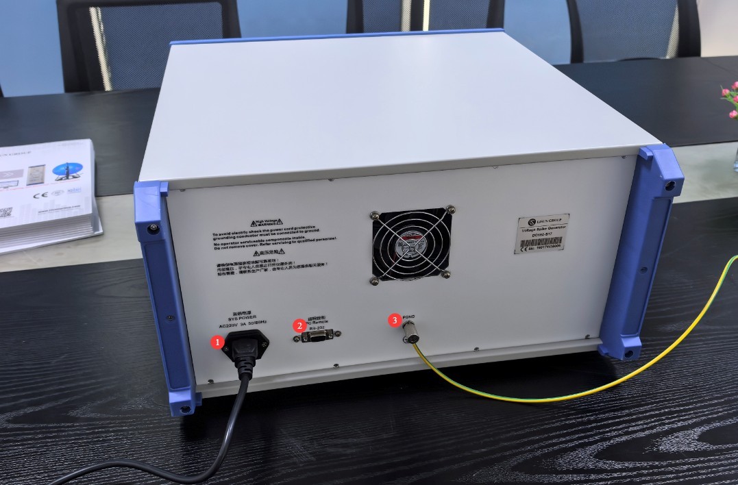
Gambar 3
3.1.2 Bagian Depan Perangkat
| Jumlah | Note |
| ① | EUT Power Indicator Light |
| ② | High-Voltage Indicator Light |
| ③ | A suitable external power source must be connected to the EUT. |
| ④ | Must be connected to the EUT |
| ⑤ | 50Ω Impedance Switch |
| ⑥ | Oscilloscope Interface: To view the device’s output waveforms, connect it to an oscilloscope using a coaxial cable. |
| ⑦ | Saklar daya |
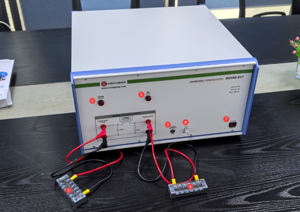
Gambar 4
Note: The 50Ω impedance switch is only used when connecting an oscilloscope to view waveforms; do not turn it on during normal testing.
3.2 Preparing the PAD
3.2.1 PAD Network Connection
Nyalakan DO160-S17 device and the PAD. Swipe down from the top of the PAD screen to find the Wi-Fi option.
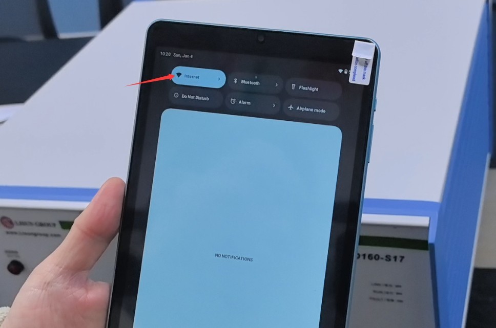
Gambar 5
Tap to connect to the Wi-Fi signal emitted by the DO160-S17 perangkat.
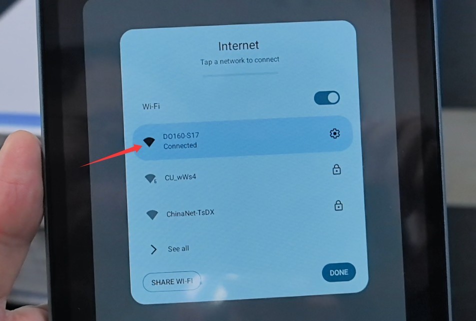
Gambar 6
Gambaran Umum Program 3.2.2
Ketuk DO160-S17 .
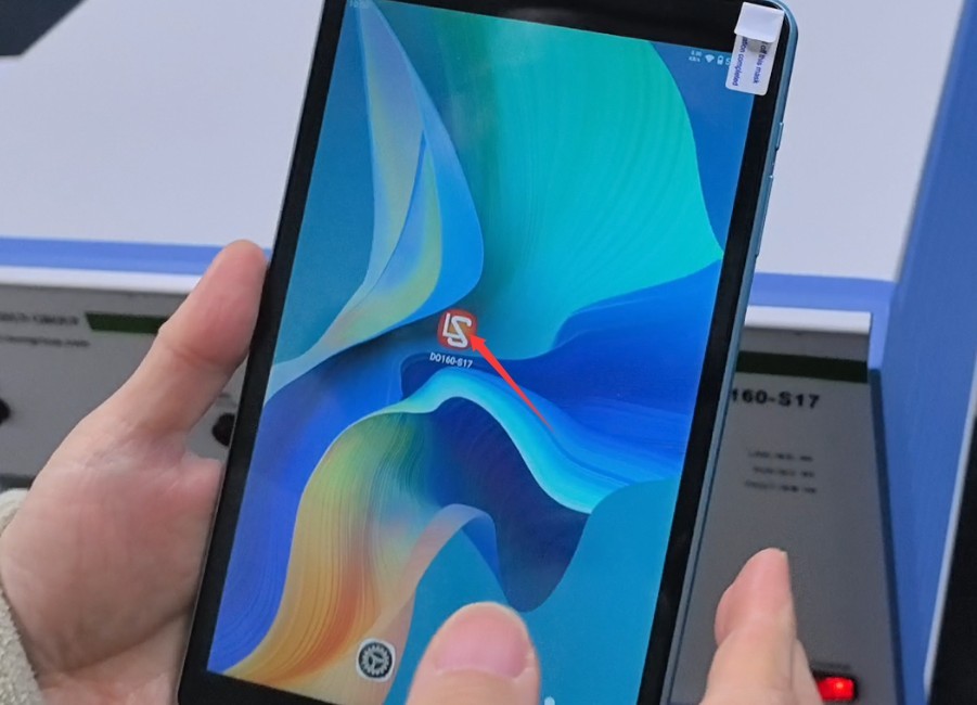
Gambar 7
| Jumlah | Note |
| ① | Help Interface (This feature is still under development; there is no need to access it at this time) |
| ② | Buka Antarmuka Pengujian |
| ③ | Switch the language to Chinese |
| ④ | Switch the language to English |
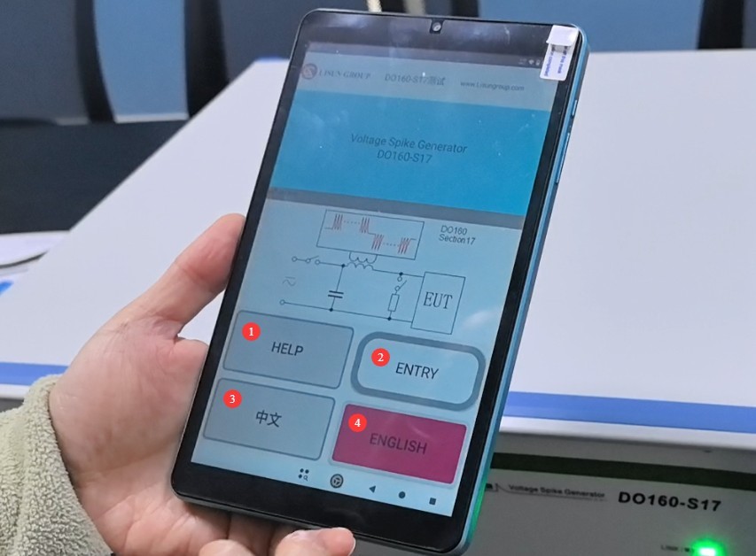
Gambar 8
Go to the test interface.
| Jumlah | Note |
| ① | Set the pulse voltage and polarity within the range of 5–1000 V |
| ② | Set the number of pulses per minute, within the range of 10 to 120 |
| ③ | Set the pulse train duration t1, 1–600 seconds |
| ④ | Set the pulse train interval t2 to a value between 1 and 6 seconds. |
| ⑤ | Set the cycle interval t3 to a value between 1 and 10 seconds. |
| ⑥ | Set the number of iterations, ranging from 1 to 100 |
| ⑦ | Automatic Pulse Voltage Polarity Switching |
| ⑧ | Click to turn the EUT’s power on or off |
| ⑨ | Click to start or stop the test |
| ⑩ | System Parameters screen—no action required |
| ⑪ | System Information screen—no action required |
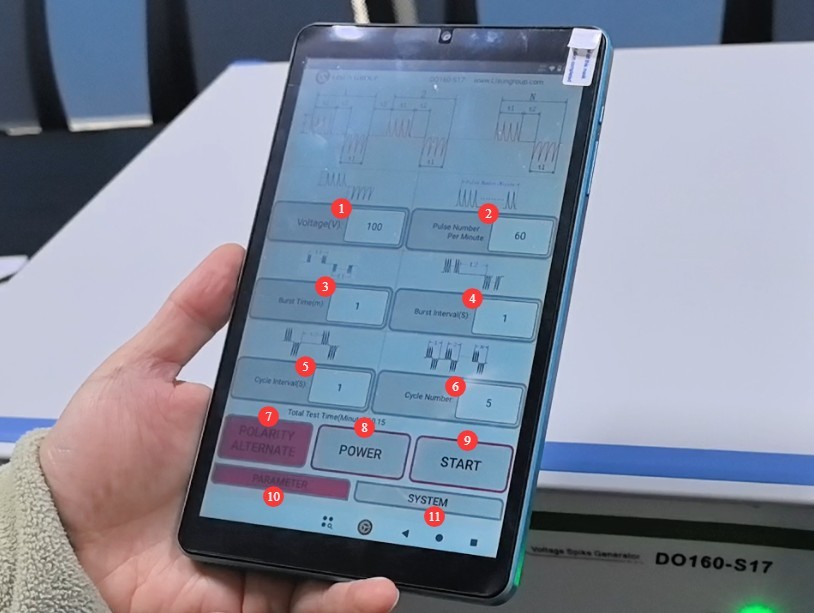
Gambar 9
4. Voltage Spike Test
4.1 Prosedur Uji
Refer to Chapter 3 to connect all cables, connect to the PAD network, and configure all test parameters.
Press the “POWER” button to turn on the EUT’s power. At this point, the EUT power indicator light on the front panel of the DO160-S17 device will illuminate, putting the EUT into normal operating mode.
Click “START” to begin the experiment.
4.2 Menentukan Apakah EUT Telah Lulus Uji
During the test (while the pulse is being applied), the EUT must meet the following requirements; otherwise, it will be deemed non-compliant:
The following are not permitted: smoke, fire, sparking, overheating of the enclosure (exceeding the EUT’s specified maximum operating temperature), or insulation breakdown (equipment leakage current exceeding the standard limit, e.g., ≥5 mA);
The following are not permitted: short circuits in power or signal lines, blown fuses (other than those intended as part of the EUT’s own protection design), or permanent safety failures such as the burning out of internal components.
The EUT must maintain its core functions without interruption (unless the standard or the EUT specifications permit a “temporary suspension of non-safety-related functions”);
Avionics EUTs (such as communication equipment and control modules): Functional anomalies that could affect safe operation—such as communication interruptions, data loss, or the erroneous triggering or failure of control commands—are not permitted;
Permissible Transient Phenomena: If the EUT incorporates its own immunity design, “brief performance fluctuations” (such as a slight decrease in signal amplitude or a response delay of ≤100 ms) may occur; however, the system must automatically recover within 1 second after the pulse ends, and core functions must not be affected.
5. Prosedur Pasca-Ujian
5.1 Tes Dihentikan
If the EUT is visibly damaged during the test, immediately tap “Stop Test” on the touchscreen and tap “Power” to turn off the EUT.
If no abnormalities occur during the test, wait for the test to end automatically, then click “Power” to turn off the EUT’s power.
Wait 5 minutes to ensure that the high-voltage capacitors inside the main unit have fully discharged, then replace the EUT for testing, or turn off the power to the main unit and the Isolation Transformer.
5.2 Pembersihan dan Pengorganisasian Pasca-Pengujian
Bersihkan area pengujian dan lap dengan kain kering. Jangan gunakan alkohol atau bahan pembersih korosif.
Pulse testing is a destructive test; it does not automatically generate a test report, and a person must manually verify whether the EUT has passed the test.
5.3 Penyimpanan Peralatan
5.3.1 Persyaratan Penyimpanan Jangka Pendek
Jika peralatan tersebut digunakan untuk operasi rutin, tidak diperlukan tindakan lebih lanjut setelah pembersihan selesai dilakukan setelah setiap pengujian.
5.3.2 Persyaratan Penyimpanan Jangka Panjang
Jika perangkat tidak akan digunakan dalam jangka waktu lama (lebih dari satu bulan), harap lepaskan semua kabel dan tutupi perangkat dengan penutup debu untuk mencegah penumpukan debu.
Perangkat ini sebaiknya dinyalakan sekali sebulan selama setengah jam saja untuk mencegah penuaan komponen listrik (seperti kapasitor dan kontaktor).
6. Pemecahan Masalah dan Penyelesaian Masalah Umum
6.1 Perangkat tidak mau menyala
Gejala: Setelah menyalakan sakelar daya, perangkat tidak merespons (lampu indikator tidak menyala, dan kipas tidak berputar).
Kemungkinan penyebabnya: ① Kabel daya tidak terhubung dengan benar atau rusak; ② Tegangan suplai tidak normal; ③ Sekring putus; ④ Varistor (MOV) terbakar.
Troubleshooting: Ensure the power cord is intact and securely connected. Power supply issues—such as unstable voltage, excessive voltage, or harmonic interference—can cause the fuse or varistor to burn out. We recommend using a regulated, clean sine-wave AC power supply to power the device. Replace the fuse or varistor with one of the same type.
Gambar di bawah ini menunjukkan lokasi sekering:
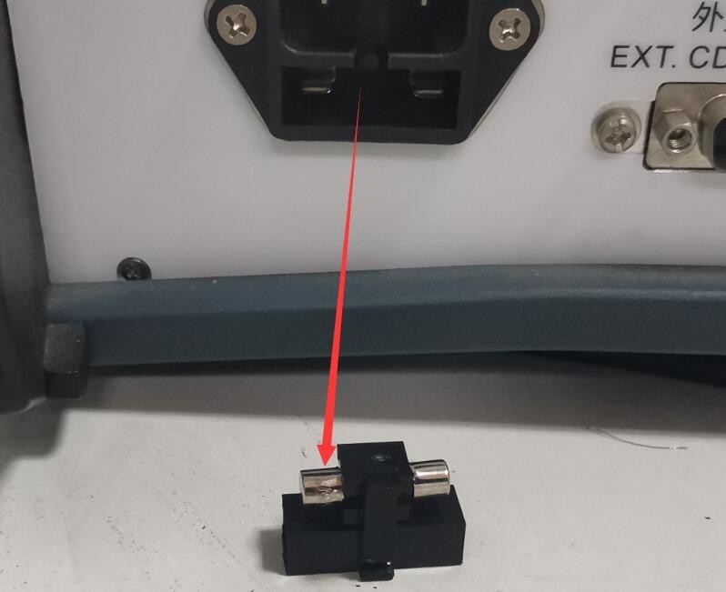
Gambar 10
Gambar di bawah ini menunjukkan lokasi varistor (MOV) di dalam catu daya yang telah difilter:
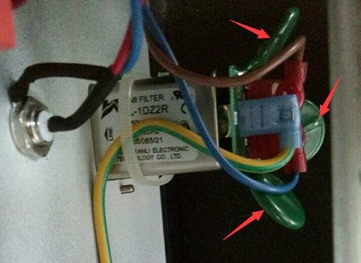
Gambar 11
6.2 Restart Perangkat Otomatis
Symptom: The device automatically restarts during pulse output.
Kemungkinan penyebab: Kabel ground tidak terhubung dengan benar.
Solution: Connect the PGND grounding terminal on the back of the host unit to ground, and ensure that the grounding resistance is ≤4Ω. Otherwise, high voltage may not be safely dissipated, causing the device to automatically restart.
6.3 The EUT Power Supply Fails to Turn On
Symptom: When the “POWER” button is pressed, the EUT does not power on.
Possible cause: 50Ω impedance switch.
Procedure: The 50Ω impedance switch is intended solely for connecting an oscilloscope to view waveforms. Do not turn it on during normal testing; otherwise, power will not be supplied to the EUT, and testing cannot proceed normally.