
 Inggris
 中文简体
中文简体 Русский
 Español
 Português
 Türkçe
 العربية
 Deutsch
 Polski
 Italiano
 Français
 한국어
한국어 ไทย
ไทย Tiếng Việt
 日本語
日本語





























Kabinet Pemuatan Lampu Tungsten/Halogen
Pengguna manual
berlaku LISUN models: DFX-WD20A
1. Membuka Kemasan dan Mengenal Peralatan Secara Dasar
1.1 Spesifikasi Teknis Utama
1.1.1 DFX Tungsten Filament Lamp Load Cabinet
Power Supply: Single-phase AC 220 ± 10% / 50 Hz with ground wire;
Digital Voltmeter: Range 0–300 V, accuracy ±0.5% ±2d;
Digital ammeter: Range 0–40 A, accuracy ±0.5% ±2d;
Digital Power Meter: Range 0–9 kW, Accuracy ±0.5% ±2d;
Load Configuration: Built-in 3 sets of multi-bulb 200W tungsten/halogen lamp combinations, with cyclic power supply;
Number of output channels: 1;
Load capacity: 7.5 kVA;
The maximum output current is 20 A; the load is automatically disconnected when the current exceeds 22 A;
The maximum output voltage is 300 V; when it exceeds 305 V, the load is automatically disconnected;
Selecting the number of tungsten filament lamps/halogen lamps: Each lamp has a power rating of 200 W, available in sets of 1, 2, 3, 4, 10, or 10 lamps;
Counter: Preset range of 0 to 999999;
Features a long-stick protection function: The upper limit for long-stick time can be preset from 0 to 99 seconds.
1.1.2 Mesin Uji Ketahanan Soket dan Sakelar Seri CZKS
| LISUN Pilih Model | CZKS-3 | CZKS-3P | CZKS-3S | CZKS-3A |
| Workstation | 2 Stopkontak + 1 Sakelar | stopkontak 3 lubang | 3 Beralih | 1 Stopkontak + 2 Sakelar |
| Drive Type | Pneumatic drive; customer-supplied air source: 0.8 MPa | |||
| Metode Pengendalian | PLC + Layar Sentuh Ekstra Besar | |||
| Waktu Menyalakan/Mematikan | 0–99.9 detik per menit (dapat disesuaikan) | |||
| Jumlah Tes | 0–999999 kali (preset) | |||
| tes Run | Linear: -40 to 110 mm (presettable); Rotation: 0 to 360° (presettable) | |||
| Tingkat Uji | Linier: 0–100 mm/s (pengaturan awal); Rotasi: 0–90°/s (pengaturan awal) | |||
| Contoh Perlengkapan | Comes standard with a universal clamp that can be adjusted up and down (other special clamps can be custom-made according to customer requirements) | |||
| LISUN Pilih Model | CZKS-6 | CZKS-6P | CZKS-6S | CZKS-6X |
| Workstation | 3 Stopkontak + 3 Sakelar | stopkontak 6 lubang | 6 Beralih | Jumlah Stopkontak + Sakelar Sesuai Pesanan |
| Drive Type | Pneumatic drive; customer must provide their own air supply: 0.8 MPa | |||
| Metode Pengendalian | PLC + Layar Sentuh Ekstra Besar | |||
| Waktu Menyalakan/Mematikan | 0–99.9 detik per menit (dapat disesuaikan) | |||
| Jumlah Tes | 0–999999 kali (preset) | |||
| tes Run | Linear: -40 to 110 mm (presettable); Rotation: 0 to 360° (presettable) | |||
| Tingkat Uji | Linier: 0–100 mm/s (pengaturan awal); Rotasi: 0–90°/s (pengaturan awal) | |||
| Contoh Perlengkapan | Comes standard with a universal clamp that can be adjusted up and down (other special configurations can be customized according to customer requirements) | |||
1.2 Pemeriksaan dan Verifikasi Aksesori Saat Membuka Kemasan
1.2.1 Membuka Kemasan dan Pemeriksaan Visual
Saat membuka kemasan perangkat, tangani dengan hati-hati untuk menghindari goresan pada casing dengan alat tajam. Setelah membuka kemasan, periksa terlebih dahulu bagian luar perangkat untuk memastikan tidak ada deformasi atau penyok yang terlihat, dan tombol-tombolnya tidak rusak atau longgar.
Jika Anda melihat adanya kerusakan atau perubahan bentuk pada peralatan atau aksesori, jangan nyalakan daya. Segera hubungi kami.
1.2.2 Unit Utama dan Aksesoris
Load cabinet: 1 unit; CZKS life tester: 1 unit.
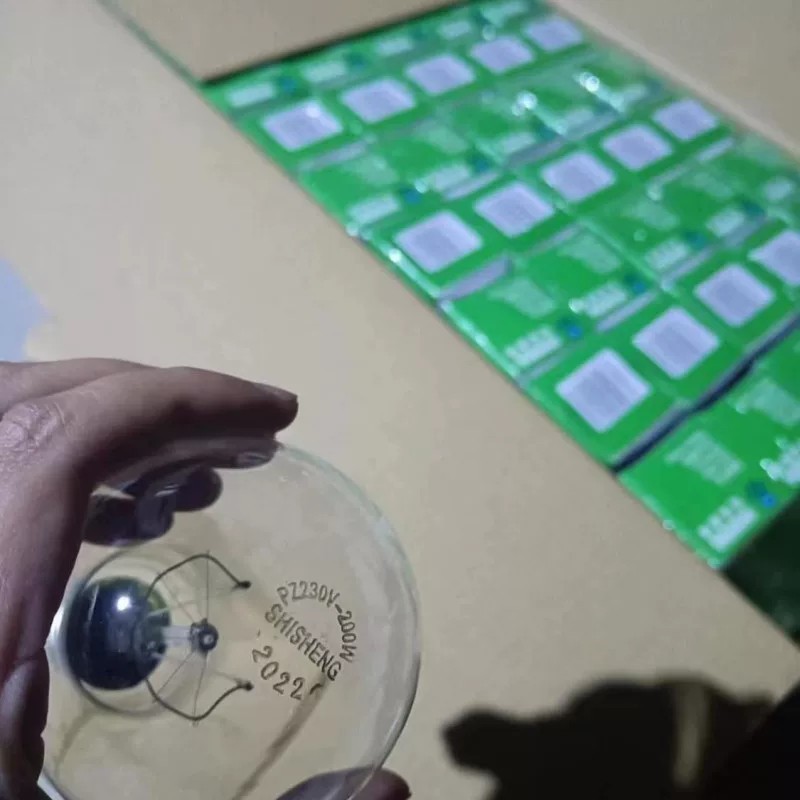
Standard accessories: 200W tungsten bulbs—52 in total (32 for the load cabinet, with the remaining 20 as spares).
Gambar 1
Catatan: LISUN switch life tester must be used in conjunction with an air compressor. Users may purchase one from LISUN or provide their own. If providing your own, please ensure it is capable of delivering compressed air at 0.8 MPa. An air hose with an 8 mm outer diameter is required for connection to the switch life tester.
Tautan unduhan untuk manual pengguna digital, kartu garansi, dan dokumen lainnya telah dikirimkan kepada Anda melalui email. Silakan unduh sesegera mungkin. Jika Anda melewatkan email tersebut, jangan ragu untuk menghubungi kami untuk meminta tautan unduhan lagi.
1.3 Deskripsi Struktur Peralatan
1.3.1 Kabinet Pemuatan
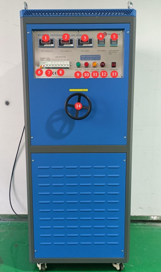
Front of the load cabinet:
① Load (tungsten filament lamp) voltage display; ② Load current display; ③ Load power display; ④ Number of tests: the top line shows the current number of tests performed, and the bottom line shows the set total number of tests;⑤ Long-duration stick-on protection time: the top line shows the current load on-time, and the bottom line shows the set long-duration stick-on time. Once the load’s single on-time reaches the set long-duration stick-on time, the load cabinet will sound an alarm and automatically cut off the output; ⑥ Load cabinet power switch; ⑦ Load power switch;⑧ Tungsten filament lamp quantity selector switch; combinations can be freely configured as needed; ⑨ Enable load output; ⑩ Disable load output; ⑪ Load on/off indicator light / Alarm reset button; ⑫ Alarm; ⑬ Cooling fan switch; ⑭ Load voltage adjustment dial.
Gambar 2
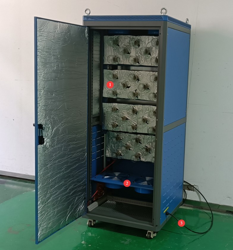
Left side and interior of the load cabinet:
① Tungsten filament lamp mounting slots—please install tungsten filament lamps in all 32 slots before use; ② Cooling fan; ③ Power cord for the load cabinet.
Gambar 3
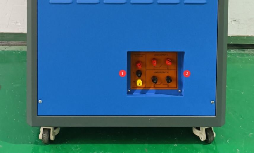
Right side of the load cabinet:
① The three terminals on the left are used to connect a separate power supply to power the tungsten filament lamp; ② The four terminals on the right are used to connect to the switch life tester and the test switch.
Gambar 4
1.3.2 Mesin Uji Ketahanan
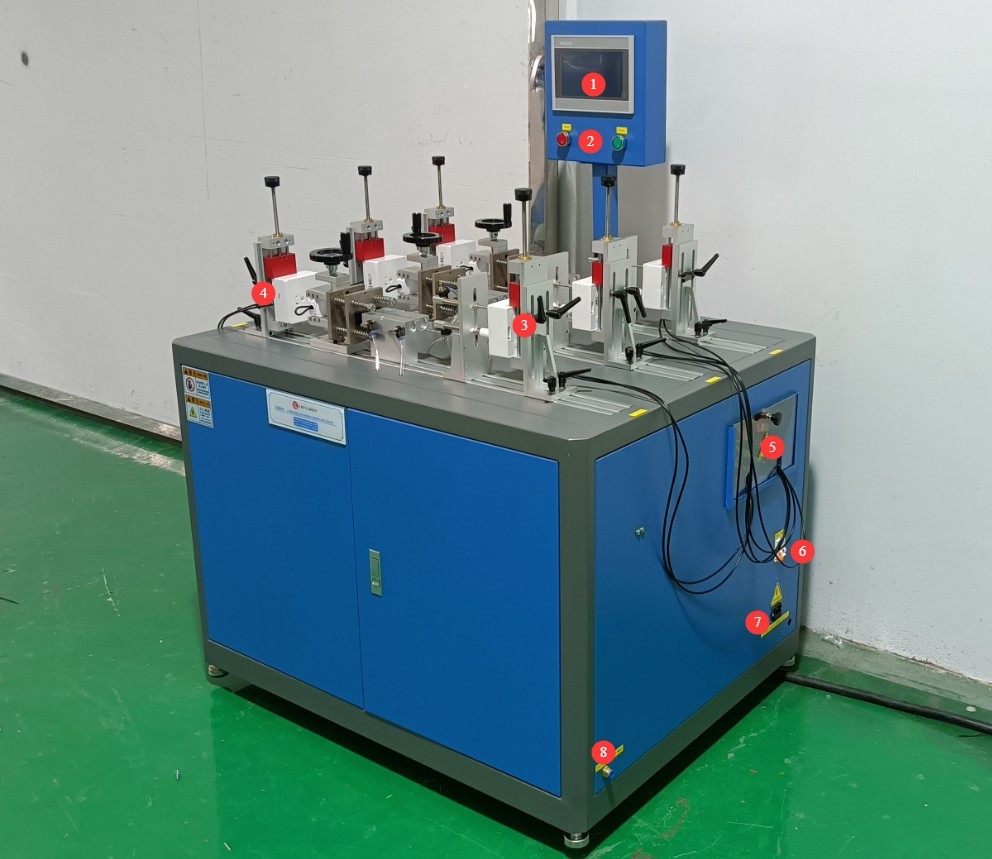
Mesin uji ketahanan tersedia dalam dua seri: seri 3 stasiun. CZKS-3 dan 6 stasiun CZKS-6Terdapat dua jenis perlengkapan: perlengkapan untuk menguji soket dan perlengkapan untuk menguji sakelar. Dengan mengambil CZKS-6 Model sebagai contoh:
① Layar sentuh; ② Sakelar daya; ③ Perlengkapan sakelar; ④ Perlengkapan stopkontak; ⑤ Blok terminal; ⑥ Pemutus sirkuit; ⑦ Soket kabel daya; ⑧ Sambungan kompresor udara.
Gambar 5
2. Tindakan Pencegahan Keamanan
2.1 Keamanan Listrik
2.1.1 Koneksi Daya
220V single-phase power; power outlets must comply with safety standards, have proper grounding, and have a rated current that matches the equipment’s power rating.
Note: The load cabinet itself does not have a high power rating; its maximum current is less than 1 A. However, tungsten filament lamps draw a significant amount of power when in operation. Please check the nameplate and the markings on the terminal blocks, and select a suitable power supply.
2.1.2 Spesifikasi Pembumian
The equipment must be reliably grounded, with a grounding resistance of ≤4 Ω. Do not use gas pipes, non-metallic water pipes, or neutral wires as substitutes for the grounding wire. After grounding is complete, use a Grounding Resistance Tester to measure the grounding resistance. Power may only be applied after confirming that the requirements are met, to prevent electric shock, equipment malfunctions, or measurement errors caused by poor grounding.
2.2 Keselamatan Operasional
Sebelum melakukan pemasangan kabel, pemeriksaan, atau perawatan peralatan, Anda harus mematikan sakelar daya peralatan dan catu daya utama, serta memastikan tidak ada tegangan sisa sebelum melanjutkan;
Jangan mengoperasikan sakelar daya peralatan, layar sentuh, atau tombol instrumen dengan tangan basah untuk menghindari risiko sengatan listrik;
Jangan meletakkan benda asing apa pun (seperti perkakas atau kertas) di dalam kabinet kontrol listrik untuk mencegah debu atau benda asing menyebabkan korsleting atau merusak komponen;
Do not plug in or unplug power cords or signal cables while the equipment is running, to prevent short circuits that could damage the controller or electrical components.
2.3 Keselamatan Lingkungan
The equipment should be placed in a dry environment free of corrosive gases and flammable or explosive materials.
The equipment must be installed in an air-conditioned room, with the ambient temperature maintained between 5°C and 35°C and relative humidity ≤ 85%.
The distance between the equipment and walls, as well as surrounding structures (such as other testing equipment and shelving), must be at least 1000 mm to facilitate maintenance; at least 2000 mm of space must be left in front of the equipment to ensure smooth operation and keep the surrounding area free of obstructions;
Peralatan harus diletakkan di permukaan yang rata dan kokoh; tinggi kaki peralatan dapat disesuaikan.
2.4 Lainnya
Untuk hal-hal yang tidak tercakup dalam panduan ini, harap berhati-hati atau hubungi kami.
3. Pengenalan Program Layar Sentuh untuk Mesin Uji Ketahanan
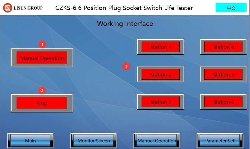
3.1 Halaman Kerja
① Sakelar Manual/Otomatis; ② Uji Mulai/Berhenti; ③ Daftar Stasiun.
Gambar 6
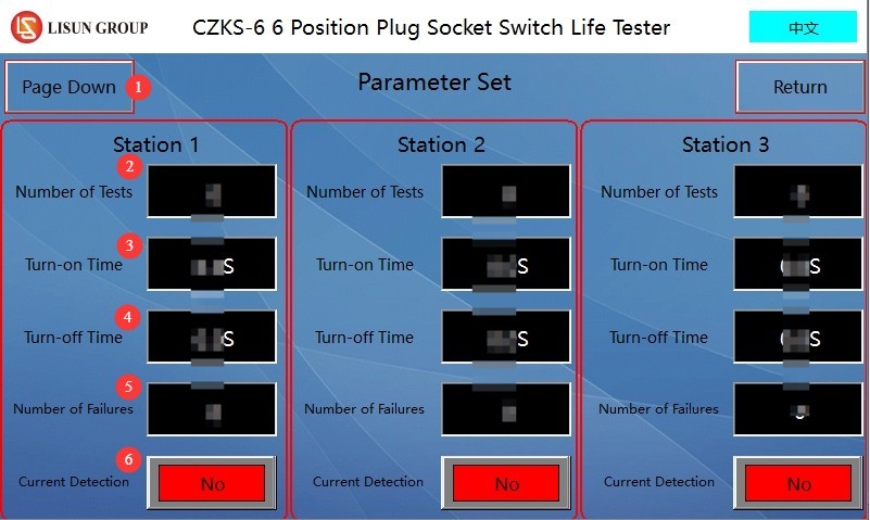
3.2 Halaman Pengaturan Parameter
① Navigasi halaman; ② Jumlah total pengujian; ③ Waktu pemuatan aktif; ④ Waktu pemuatan nonaktif; ⑤ Jumlah upaya pemantauan arus yang gagal; ⑥ Apakah arus sedang dipantau.
Gambar 7
Catatan: Pengguna dapat mengatur parameter yang berbeda untuk stasiun kerja yang berbeda.
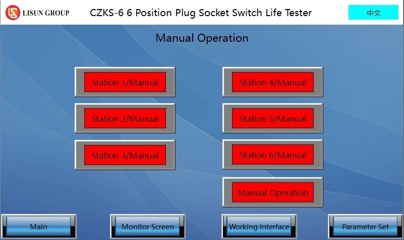
3.3 Jendela Manual
Klik tombol kontrol manual untuk stasiun kerja yang bersangkutan untuk menyesuaikan posisi perlengkapan secara manual di stasiun kerja tersebut.
Gambar 8
3.4 Rekaman Pengawasan
① Navigasi halaman; ② Jalankan/Jeda; ③ Monitor saat ini; ④ Jumlah total tes; ⑤ Jumlah tes yang dilakukan; ⑥ Jumlah sesi pemantauan saat ini; ⑦ Atur ulang.
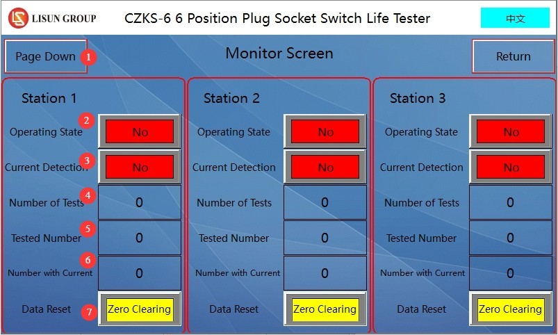
Gambar 9
4. Persiapan Sebelum Ujian
4.1 Pengkabelan Peralatan
4.1.1 Koneksi Kabel Daya
Please refer to Chapter 2. Turn on the life-cycle tester; do not turn on the load cabinet at this time.
4.1.2 Sambungan Kompresor Udara
Connect an air hose with an outer diameter of 8 mm to the endurance testing machine, then turn on the air compressor.
4.1.3 Connecting the Load Cabinet, Endurance Tester, and Specimen
The load cabinet has the following four terminals—two red and two black—as shown in the figure below.
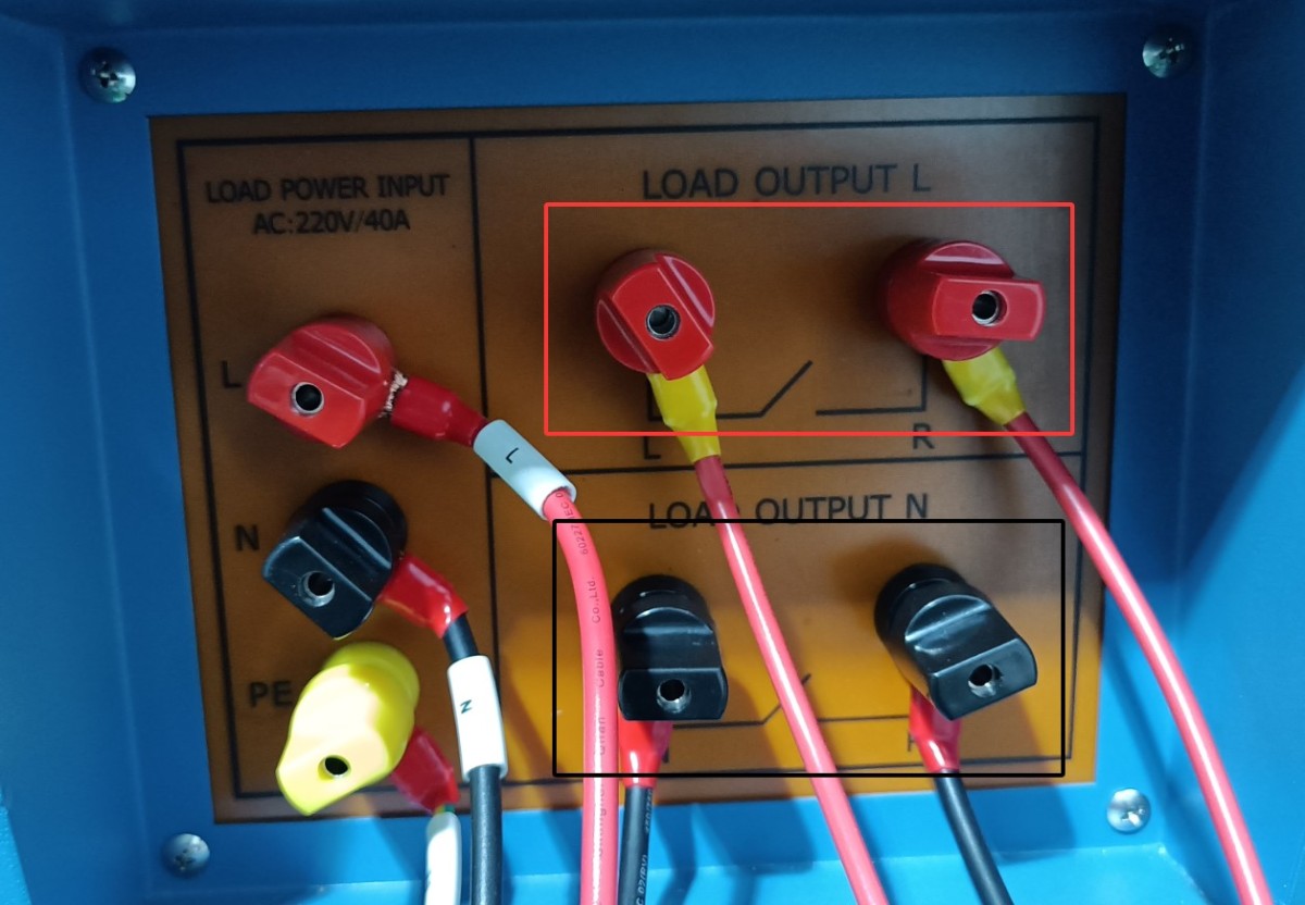
Gambar 10
4.1.3.1 Single-Pole Switch
Connect the two red terminals or the two black terminals of the load cabinet to the life tester, and then short-circuit the other two terminals.
The two terminals on the load cabinet are connected to terminals A and B on the life testing machine, and terminals A and C on the life testing machine are connected to the sample switch, as shown in the wiring diagram for workstation 4 of the life testing machine below.
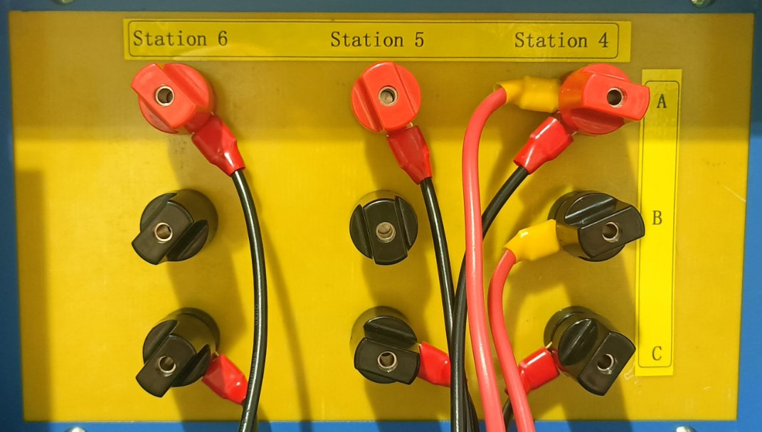
Gambar 11
4.1.3.2 Dual-Control Switch
Connect the two terminals on the load panel that are short-circuited directly to one circuit of the double-pole switch, and then connect the other circuit of the double-pole switch as described in section 4.1.3.1.
4.2 Kalibrasi Sampel
Open the manual window of the life test machine. Click the button for the corresponding test station to perform a single-cycle operation, then observe the position of the machine’s actuators. If the test specimen is a switch, adjust the machine so that when the upper actuator extends, it just closes the switch, and when the lower actuator extends, it just opens the switch.
After debugging is complete, the switch should be set to the off position.
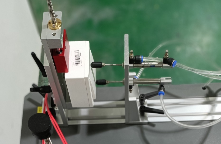
Gambar 12
5. Switch Life Test Procedure
5.1 Konfigurasi Kabinet Muat
Turn on the power switch for the load cabinet.
The number of test cycles is factory-set to 9999, and the adhesive holding time is factory-set to 90 seconds. Users can also adjust these settings as needed.
Turn on the load cabinet’s power switch, press the “Start Load Output” button, and turn on all cooling fans.
Slowly rotate the voltage adjustment dial while monitoring the test voltage until the voltage meets the test specifications. Note: When the load voltage exceeds 305 V, the device will automatically disconnect the load.
Turn on the tungsten filament lamp quantity selector switch as needed; with a maximum load of 30 tungsten filament lamps (if switches 1, 2, 3, 4, 10, and 10 are all turned on, the total number of tungsten filament lamps in use is 1 + 2 + 3 + 4 + 10 + 10 = 30). Users may also freely combine switches according to their needs.
Example: According to Clause 18.3 of standard GB/T 16915.1-2024 (IEC 60669-1:2017, Clause 18.3), when testing a 10 A, 250 V switch, the voltage required for a 200 W tungsten filament lamp is 240 V, and 15 such lamps are required.
In the manual window of the life test machine, turn on the switch for the corresponding workstation. See the figure below:
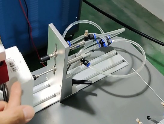
Gambar 13
After the switch is turned on, the voltage will drop slightly, requiring you to turn the voltage adjustment knob again. At this point, the test load current is 1.2 times the rated current of the sample switch, or approximately 12 A. Note: When the load current exceeds 22 A, the load cabinet will automatically disconnect the load.
Once the adjustment is complete, go to the manual control panel of the endurance tester and return the specimen to its original state by setting the specimen switch to the “OFF” position.
5.2 Menyiapkan Mesin Uji Ketahanan
Parameter Settings Interface. For each workstation, configure the total number of tests, load on time, load off time, number of failed current monitoring attempts, and whether to monitor current.
Catatan 1: Jumlah kesalahan mengacu pada jumlah kali sampel diberi daya tetapi tidak ada arus yang terdeteksi (pengujian akan berhenti secara otomatis setelah jumlah kesalahan aktual selama pengujian mencapai batas kesalahan yang ditetapkan; parameter ini tidak valid ketika pemantauan arus dinonaktifkan);
Catatan 2: Pemantauan arus hanya boleh diaktifkan ketika kabinet beban terhubung ke stasiun uji tersebut untuk pengujian.
Monitoring Interface. Used to view the test status and data for the corresponding workstation. Please click the “Reset” button for the corresponding workstation to clear the previous test data before you can begin testing at that workstation.
5.3 Uji Ketahanan Hidup
5.3.1 Memulai Tes
Masuk ke antarmuka kerja. ① Pilih stasiun kerja yang ingin Anda jalankan, ② klik untuk beralih dari manual ke otomatis, ③ klik untuk memulai pengujian.
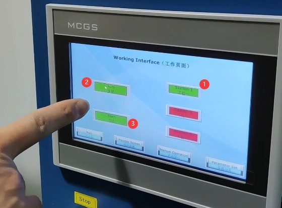
Gambar 14
5.3.2 Pemantauan Uji
Selama pengujian, Anda dapat melihat data secara real-time di layar pemantauan.
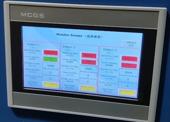
Gambar 15
5.3.3 Akhir Tes
If the number of test cycles at a life test machine station reaches the set limit, that station will stop the test and automatically place the specimen in the disconnected state. Important note: The load cabinet is still outputting power; please turn off the load output before proceeding.
If the life tester station is equipped with selective current monitoring and the number of failures during the test reaches the preset limit, the life tester will automatically stop the test at that station and automatically disconnect the test specimen. Important Note: The load cabinet will still be in the output state; please turn off the load output before proceeding with any further operations.
If a sample at a test station on the life tester is damaged during testing and remains in the “always on” state, the load cabinet will trigger an alarm after the load has been continuously applied for 90 seconds and will automatically cut off the output. Please press the alarm reset button on the front panel of the load cabinet and manually end the test for the corresponding station on the life tester.
6. Prosedur Pasca-Ujian
6.1 Melihat Data Uji yang Direkam
Akses layar pemantauan mesin uji ketahanan, periksa dan catat data uji untuk setiap stasiun.
6.2 Shutting Down
Matikan kompresor udara;
Turn off the life-cycle testing machine;
Disconnect the load output from the load cabinet, turn off the cooling fan, reset the tungsten lamp quantity selector switch to its original position, and turn off the power to the load cabinet.
6.3 Periksa Kondisi Sampel
Use a screwdriver to loosen the clamp screws, remove the tested sample, inspect the sample’s appearance (e.g., check for deformation of the socket and plug, or ablation of the switch contacts), and record the test results.
7. Pemeliharaan dan Perawatan Peralatan Harian
7.1 Pembersihan dan Perawatan
After the test is complete, wipe down the life-test machine fixtures and other components with a dry cloth; do not use corrosive cleaning agents. Remove dust from the equipment’s terminal blocks to prevent poor contact.
7.2 Pelumasan dan Perawatan
Apply lubricating oil to the sliding components of the endurance testing machine (slide rails, cylinder piston rods) to ensure smooth mechanical operation; check the fixture screws and tighten any loose parts promptly.
7.3 Penyimpanan Peralatan
7.3.1 Persyaratan Penyimpanan Jangka Pendek
Jika peralatan tersebut digunakan setiap hari, tidak diperlukan tindakan lebih lanjut setelah pembersihan selesai dilakukan setelah setiap pengujian.
7.3.2 Persyaratan Penyimpanan Jangka Panjang
Jika perangkat tidak akan digunakan dalam jangka waktu lama (lebih dari satu bulan), harap lepaskan semua kabel dan tutupi perangkat dengan penutup debu untuk mencegah penumpukan debu.
Perangkat ini sebaiknya dinyalakan sekali sebulan selama setengah jam saja untuk mencegah penuaan komponen listrik (seperti kapasitor dan kontaktor).
8. Pemecahan Masalah dan Penyelesaian Masalah Umum
8.1 Failures in Life Testing Machines
8.1.1 Mesin pengujian tidak memiliki gerakan mekanis
Causes of malfunction: Insufficient air supply pressure < 0.8 MPa, air leak at the air supply connection, or malfunction of the cylinder solenoid valve;
Solusi: Sesuaikan tekanan kompresor udara ke 0.8 MPa, ganti selang suplai udara yang bocor, dan hubungi pabrikan untuk memperbaiki katup solenoid.
8.1.2 Tidak Ada Tampilan di Layar Sentuh / Layar Sentuh Tidak Merespons
Penyebab kerusakan: Daya tidak terhubung, kabel pita layar sentuh longgar, kesalahan program PLC;
Penyelesaian Masalah: Periksa sambungan daya pada mesin pengujian dan sambungkan kembali kabel pita layar sentuh dengan benar. Jika terdapat kesalahan perangkat lunak, hubungi produsen untuk mendapatkan bantuan.
8.1.3 Workstation Gagal Memulai
Cause of failure: Current monitoring failure, short circuit in the sample wiring, or the number of tests or failures has reached the preset value;
Solusi: Periksa contoh pemasangan kabel, klik tombol “Reset” pada layar pemantauan, dan ganti modul deteksi arus jika rusak.
8.2 Kegagalan Kabinet Beban
8.2.1 Tidak Ada Keluaran Tegangan/Arus
Causes of malfunction: Main power not turned on, voltage knob not adjusted, loose terminal connections;
Prosedur: Hidupkan catu daya utama ke kabinet beban, atur kenop tegangan ke nilai nominal, dan kencangkan sekrup terminal.
8.2.2 Tampilan Abnormal pada Tabel Parameter Kelistrikan
Causes of malfunction: Corrupted parameter table, stuck voltage dial, poor sample contact;
Solusi: Ganti meteran parameter listrik, bersihkan kotoran dari meja putar, dan pasang kembali sampel untuk memastikan kontak yang tepat.
8.2.3 Alarm Peralatan Berkelanjutan
Causes of malfunction: Sample current remains active for more than 90 seconds, load overload, or a malfunctioning alarm reset button;
Troubleshooting: Check for a short circuit in the sample, reduce the load current to the rated value, and replace the alarm reset button.
8.3 Kegagalan Uji Gabungan
Failure Symptom: Frequent failures of test specimens during electrical life testing
Penyebab kerusakan: Parameter beban tidak memenuhi persyaratan standar; penyimpangan pada posisi pemasangan sampel;
Solution: Readjust the current and power factor of the load cabinet to the standard values, and adjust the mechanical position of the testing machine to ensure good contact with the sample.