
 Inggris
 中文简体
中文简体 Русский
 Español
 Português
 Türkçe
 العربية
 Deutsch
 Polski
 Italiano
 Français
 한국어
한국어 ไทย
ไทย Tiếng Việt
 日本語
日本語





























Dips Tegangan dan Gangguan Generator
Pengguna manual
berlaku LISUN Model: CSS61000-11,CSS61000-11T,CSS61000-11T-100A,CSS61000-11T-32A
1. Membuka Kemasan dan Mengenal Peralatan Secara Dasar
1.1 Spesifikasi Teknis Utama
| LISUN Pilih Model | CSS61000-11 | CSS61000-11T | CSS61000-11T-32A | CSS61000-11T-100A |
| Gelombang Output | Gelombang Sinus AC | |||
| Rentang voltase | 0–110% of 220 V | 0–110% of 380 V | ||
| Internal IEC Rating | 100%, 80%, 70%, 40%, 0% | |||
| Drop Angle Setting | 0°–360° (in 1° increments) | |||
| Duration of the voltage change | 0.5–9999.5 T | |||
| Interval between voltage changes | 1 s–9999 ms | |||
| Number of times the voltage changes | 0 – 9999 kali | |||
| Metode Kerja | Fully Automatic Free-Fall Test | Select any one to three phases that drop simultaneously | ||
| Metode Pemicu | Manual, Automatic, and 50 ms | |||
| Power Supply for the EUT | Single-phase AC 220 V ±10%, max. 16 A | Three-phase AC 380 V ±10%, max. 20 A per phase | Three-phase AC 380 V ±10%, max. 32 A per phase | Three-phase AC 380 V ±10%, max. 100 A per phase |
| Catu Daya Instrumen | Tegangan AC 220 V (110 V opsional) ±10%, 50/60 Hz | |||
1.2 Pemeriksaan dan Verifikasi Aksesori Saat Membuka Kemasan
1.2.1 Membuka Kemasan dan Pemeriksaan Visual
When unpacking the device, handle it gently to avoid scratching the casing with sharp tools. After unpacking, first inspect the exterior of the device to ensure there is no obvious deformation or dents, and that the buttons are not damaged or loose.
Jika Anda melihat adanya kerusakan atau perubahan bentuk pada peralatan atau aksesori, jangan nyalakan daya. Segera hubungi kami.
1.2.2 Unit Utama dan Aksesoris
Main Equipment: 1 Voltage Dips and Interruptions Generator.
The CSS61000-11 single-phase EUT device looks as follows:
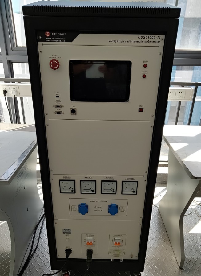
Gambar 1
The CSS61000-11T three-phase EUT device looks as follows:
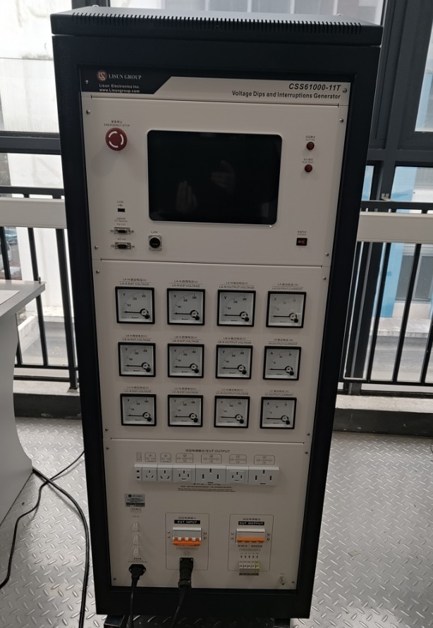
Gambar 2
Standard Accessories: ① Equipment power cord; ② EUT (test specimen) input power supply cord; ③ EUT output connection cable; ④ Coaxial cable, which can be connected to an external oscilloscope to view waveforms; ⑤ Ground wire.
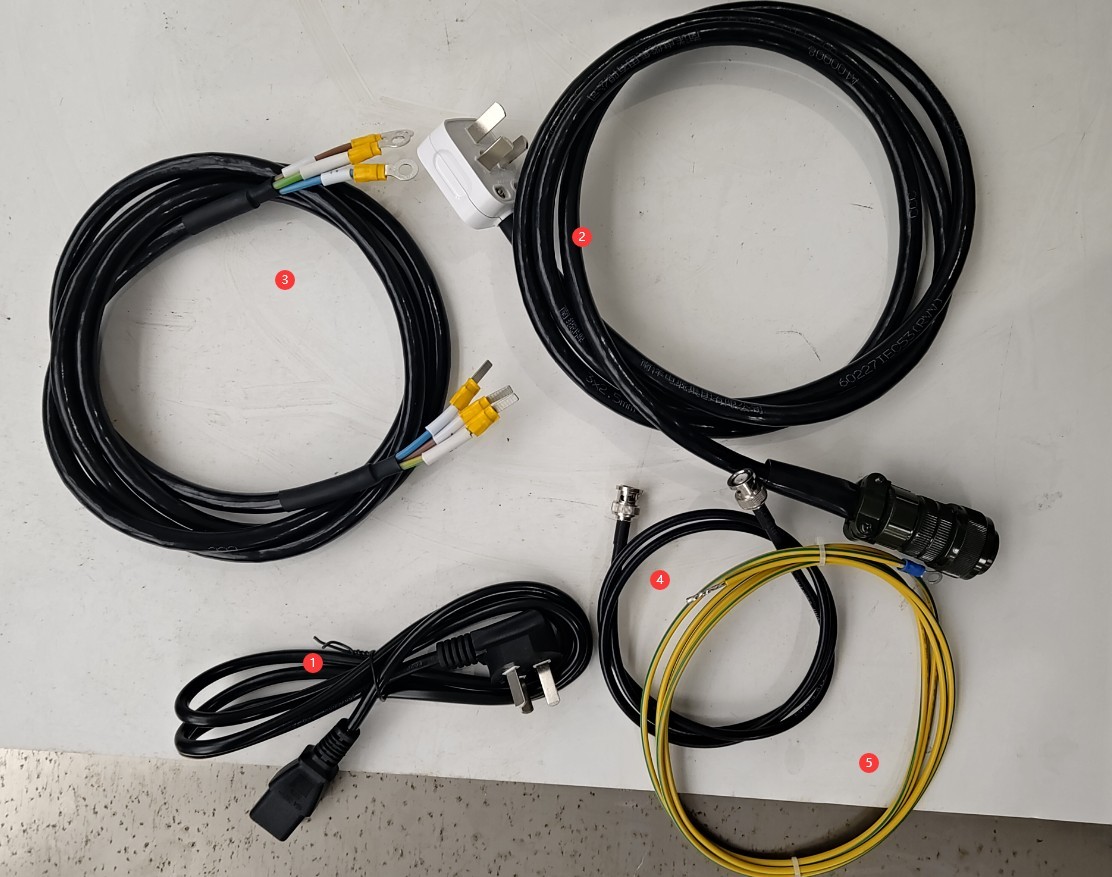
Gambar 3
Tautan unduhan untuk manual pengguna digital, kartu garansi, dan dokumen lainnya telah dikirimkan kepada Anda melalui email. Silakan unduh sesegera mungkin. Jika Anda melewatkan email tersebut, jangan ragu untuk menghubungi kami untuk meminta tautan unduhan lagi.
2. Tindakan Pencegahan Keamanan
2.1 Pedoman Penempatan
Ensure the ambient temperature is between 15°C and 35°C, relative humidity between 30% and 60% (no condensation), and atmospheric pressure between 86 kPa and 106 kPa to prevent high-voltage short circuits or damage to the equipment caused by moisture;
The premises must be free of strong electromagnetic interference, corrosive gases, flammable or explosive materials, and dust, and must be well-ventilated;
Place it on a stable workbench; avoid tilting or inverting it, and keep it away from sources of vibration;
The equipment must be placed at least 1000 mm away from walls and surrounding structures (such as other testing equipment and shelving) to facilitate maintenance; at least 2000 mm of space must be left in front of the equipment to ensure smooth operation and keep the surrounding area free of obstructions.
2.2 Standar Keselamatan Listrik
2.2.1 Pemeriksaan Keamanan
Verify that the equipment’s power supply voltage matches the supply voltage, and ensure that the power supply is properly grounded and that the grounding wire is free of damage or looseness.
Grounding Requirements: The protective grounding terminal (PG) on the main unit must be connected to ground, with a grounding resistance of ≤4 Ω.
The EUT’s ground terminal must be at the same potential as the equipment’s grounding system to ensure test safety.
2.2.2 Persyaratan Keselamatan untuk Prosedur Operasional
Operators must undergo professional training and be familiar with this manual and the relevant standards. Non-professionals are prohibited from operating or disassembling the equipment. The equipment contains high-voltage circuits; opening the cover may pose an electric shock hazard. Contact the manufacturer’s technical staff for repairs.
While the equipment is in operation, do not touch the EUT’s input and output wires or terminals.
Before switching connections or replacing the EUT, you must first ensure that the EUT’s power input and output switches are turned off.
Jika melibatkan beberapa orang, tetapkan peran dan tanggung jawab dengan jelas, dan konfirmasikan satu sama lain sebelum memulai pengujian untuk menghindari kesalahan.
2.3 Lainnya
Untuk hal-hal yang tidak tercakup dalam panduan ini, harap berhati-hati atau hubungi kami.
3. Persiapan Sebelum Ujian
3.1 Preparation of the EUT (Test Item)
Inspect the EUT to ensure there are no visible damages, no water ingress, and no rust, and that the power connector is intact.
Prepare an external power supply based on the EUT’s rated voltage and current.
3.2 Verification of Standard Parameters
3.2.1 Single-Phase Test Parameters (GB/T 17626.11)
| Tingkat Tes | Drop Voltage (relative to UT) | Durasi | Skenario yang Berlaku |
| Level 1 | UT 80% | 10 ms/20 ms/50 ms | Environment with minimal interference |
| Level 2 | UT 70% | 10 ms/20 ms/100 ms | General Industrial Environments |
| Level 3 | UT 40% | 20 ms/50 ms/200 ms | Lingkungan Industri yang Keras |
| Level 4 | 0% UT (Total Drop) | 50 ms/100 ms/500 ms | Extreme Interference Environments |
3.2.2 Three-Phase Test Parameters (GB/T 17626.34)
Drop Type: Single-phase drop, two-phase drop, three-phase drop (select according to test requirements).
Synchronization Requirements: During a three-phase drop, the initial phase difference between phases must be ≤5°, and the duration deviation must be ≤1 ms.
Recovery Requirements: After the drop ends, the voltage recovery time must be ≤ 10 ms, with no overshoot (overshoot voltage ≤ 110% UT).
3.3 Introduction to the Equipment Front Panel and Wiring
① Emergency stop switch; ② USB port, which can be used to connect a mouse or update the software; ③ The remaining three ports are reserved; if not specified at the time of purchase, they have no function;④ Touchscreen; ⑤ EUT power indicator and test indicator; ⑥ Power switch; ⑦ EUT rated voltage display; ⑧ Voltmeter displaying the EUT voltage drop; ⑨ Voltmeter displaying the EUT current voltage; ⑩ Ammeter displaying the EUT current;⑪ Connects to the EUT; ⑫ Connects to the EUT; ⑬ Connects to an external oscilloscope to view the voltage drop waveform; ⑭ Power cord; connect as specified in 2.2.1;⑮ EUT power input terminal; connect to an external power source to supply power to the EUT; ⑯ EUT power input switch; ⑰ EUT connection port; ⑱ EUT power output switch; ⑲ PG protective grounding terminal; connect as specified in 2.2.1; ⑳ EUT test specimen.
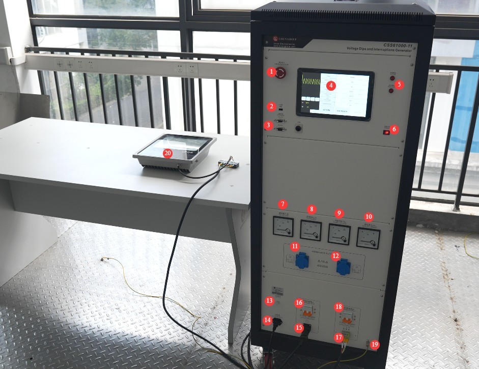
Gambar 4
Note: Based on the EUT’s maximum current and for ease of wiring, simply select one of ports ⑪, ⑫, or ⑰ for connection.
3.4 Pemanasan Peralatan dan Uji Mandiri
Turn on the power switch on the front panel of the host; the device enters standby mode, the power indicator light turns on, and the cooling fan starts.
Tunggu 5 menit agar perangkat memanas, dan periksa apakah layar sentuh menampilkan gambar dengan normal dan tidak ada pesan kesalahan.
4. Pengantar Program Layar Sentuh
4.1 Layar Awal
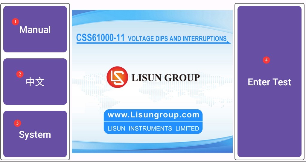
① General Precautions for Use (This feature is still under development; there is no need to access it at this time); ② Switch between Chinese and English; ③ System Information Screen; ④ Voltage and Frequency Dip Test Screen.
Gambar 5
4.2 System Information Screen
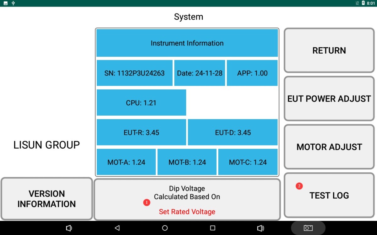
① Switch the voltage drop mode to perform the voltage drop based on either the rated voltage or the actual voltage. Example: If the rated voltage is 220 V, the actual voltage is 230 V, and the set voltage drop is 160 V, the voltage drop will be 160 V if calculated based on the rated voltage; If the voltage drop is calculated based on the actual voltage, the drop voltage will be 230/(220/160) = 167.3 V.
② Click to view the test log.
Gambar 6
4.3 Antarmuka Pengujian
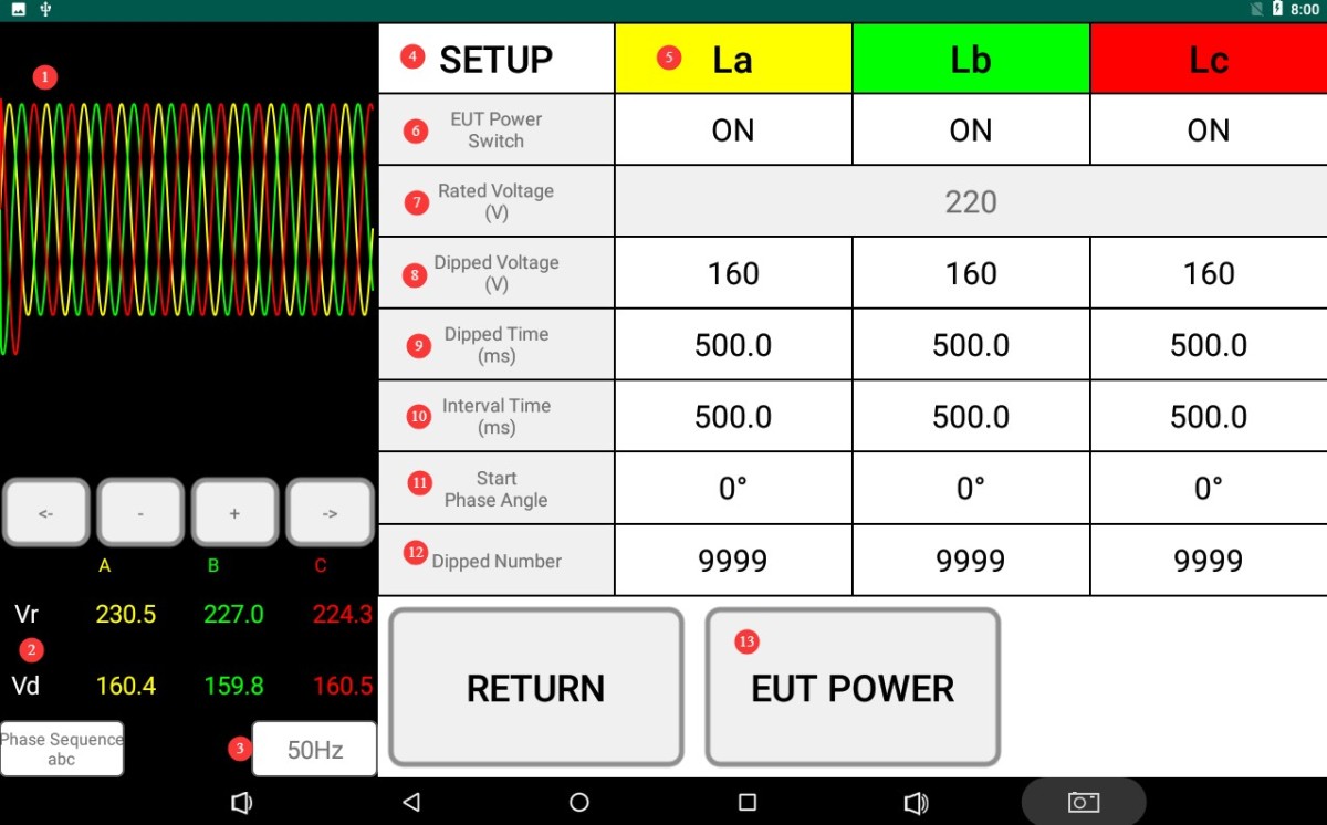
① Voltage waveform display; ② Display of the EUT’s actual voltage and voltage dip; ③ EUT frequency display;④ Special function settings; ⑤ For three-phase EUTs, test parameters can be set separately for each phase (La, Lb, Lc); ⑥ Control whether to perform a voltage dip test on a specific phase; if a dip test is not required for that phase, simply set it to OFF;⑦ Rated voltage setting; ⑧ Voltage dip setting; ⑨ Voltage dip duration setting; ⑩ Interval duration setting; ⑪ Voltage dip phase angle setting; ⑫ Number of voltage dips setting; ⑬ Click to turn the EUT power on or off.
Gambar 7
Catatan 1: Untuk CSS61000-11 single-phase EUT Voltage Dips and Interruptions Generator, after turning on the EUT input/output switch and setting the rated voltage, the generator will automatically adjust the EUT input power supply to the set rated voltage value based on the setting. The CSS61000-11T three-phase EUT Voltage Dips and Interruptions Generator does not have an automatic rated voltage adjustment function; if you need to adjust the EUT input voltage, you must adjust the external input power supply.
Note 2: If all drop tests are to be conducted at a fixed phase angle: If your EUT sample operates at 50 Hz, set both the drop time and the interval time to be integer multiples of a single cycle (20 ms). If your EUT sample operates at 60 Hz, set both the drop time and the interval time to be integer multiples of a single cycle (16.67 ms). If the set times are not integer multiples of a single cycle, only the first dip may occur at the set phase angle.
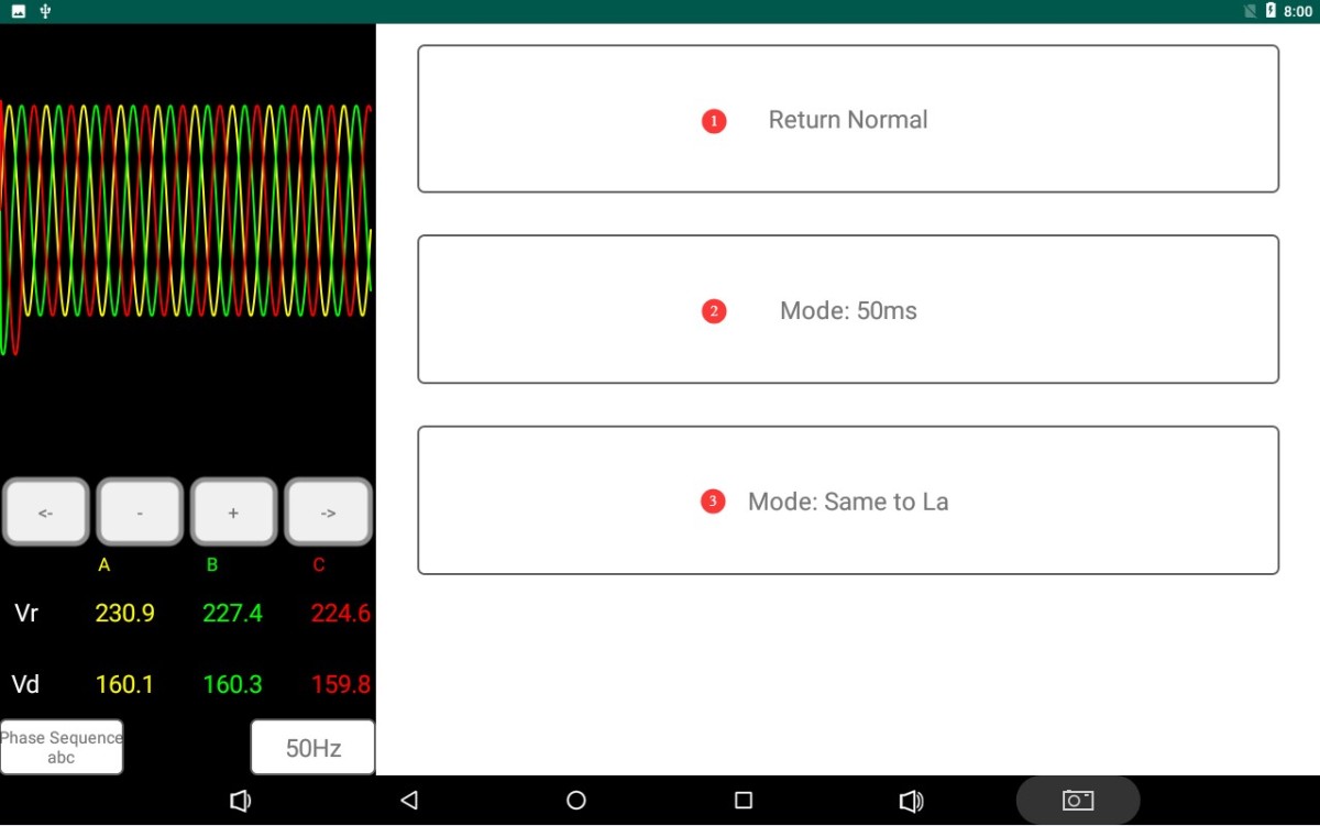
Click to enter the special features settings screen (you may choose to enable or disable this feature; it does not affect the test).① Return to the General Settings screen; ② Automatically configure settings according to the electricity meter industry standard; each drop test consists of 3 consecutive drops (spaced 50 ms apart); ③ If your device uses a three-phase circuit for drop testing, click to have Lb and Lc automatically use the settings for La.
Gambar 8
5. Voltage and Frequency Dip Test
5.1 Prosedur Operasional
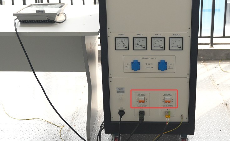
Turn on the EUT input power supply switch, and turn on the EUT power output switch.
Gambar 9
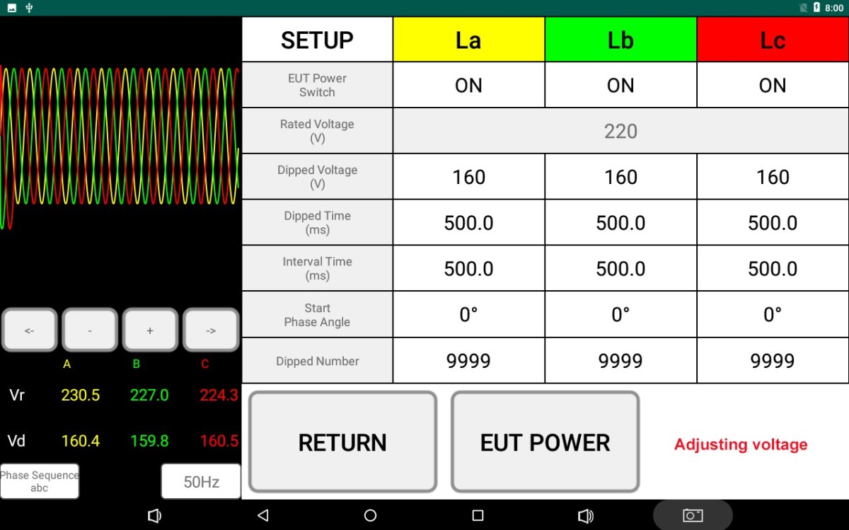
After setting all parameters on the touchscreen interface, the screen displays “Voltage Adjusting.” Observe the rated voltage and voltage dip displays on the screen, as well as the voltmeter reading. When the rated voltage (applicable only to the CSS61000-11 Single-Phase EUT Voltage Dips and Interruptions Generator) and the voltage dip are automatically adjusted to the set values, the prompt disappears.
Gambar 10
Note: When the above message appears, it indicates that the device is in the process of self-calibration; do not perform any other operations.
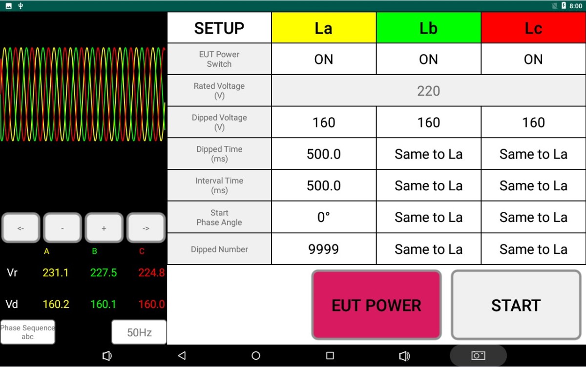
Click “EUT POWER” to connect the EUT power supply to the EUT. Follow the instructions in the EUT manual to set it to its normal operating state (e.g., power on and warm up, set the operating mode).
Gambar 11
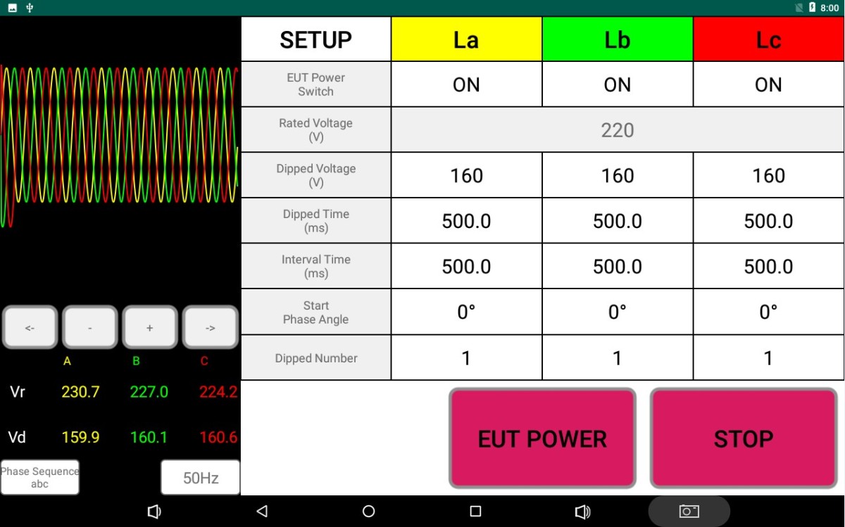
Click “START” to begin the voltage dip test.
Gambar 12
The current voltage and current of the EUT can be monitored, and the display can be switched between the rated values and the test values.
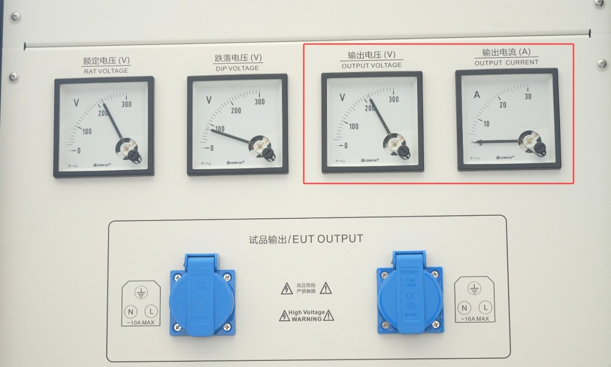
Gambar 13
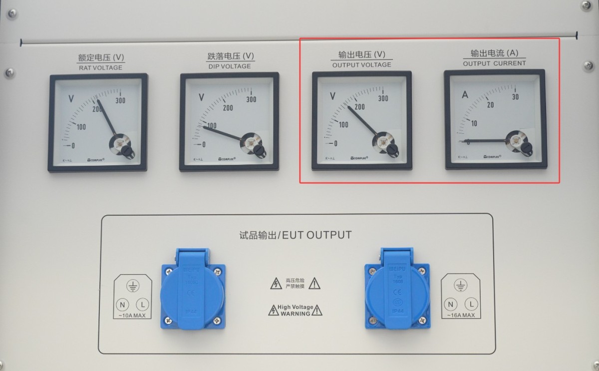
Gambar 14
Catatan: CSS61000-11 series testers are capable of testing high-power EUTs; the selected current meter is a wide-range current meter. If the EUT current is relatively low, the display may not be clearly visible, but this does not affect the test.
5.2 Menentukan Apakah EUT Telah Lulus Uji
The four-level performance classification system (A/B/C/D) specified in GB/T 17626.1 (General Principles for Immunity Testing) is adopted.
| Tingkat | Definisi | Determination Result |
| PC A | During and after the test, the EUT functioned and performed completely normally, with no abnormalities observed, and complied with the technical specifications set by the manufacturer. | By |
| PC B | Temporary loss of function or temporary degradation in performance may occur during the test; however, once the disturbance ceases, the EUT shall recover to normal operation on its own without operator intervention. | Approved (subject to product specifications) |
| PC C | During testing, a loss of function or reduced performance may occur; while the system cannot recover on its own once the disturbance ceases, it can return to normal through operator intervention (such as resetting, restarting, or reconfiguring), and no permanent damage occurs. | |
| PC D | The EUT has sustained permanent damage, experienced a software failure, or suffered data loss; or its operational metrics or performance deviate from expected values and cannot be restored | Gagal |
GB/T 17626.11-2023 (Equipment ≤ 16 A) Preferred test level:
| Jenis Tes | Test Level (Percentage of Residual Voltage) | Durasi | Skenario yang Berlaku | Recommendation Criteria |
| Penurunan tegangan | 40%, 70% | 0.01 s (half-cycle), 0.1 s, 0.5 s, 1 s | Consumer and commercial electronic devices, small industrial controllers | PC A/B (Use PC A for critical equipment) |
| Short-term interruption | 0% (Completely Interrupted) | 0.001 s (0.05 cycles), 0.01 s, 0.1 s, 1 s | All devices rated at 16A or less | PC B/C (PC B for Critical Equipment) |
| Variasi Tegangan | Step Changes: ±10%, ±20% | Sustained and Stable | Voltage-sensitive equipment (such as medical devices and precision instruments) | PC A |
GB/T 17626.34-2012 (Equipment >16A) Preferred Test Level:
| Jenis Tes | Test Level (Percentage of Residual Voltage) | Durasi | Skenario yang Berlaku | Recommendation Criteria |
| Penurunan Tegangan | 40%, 70% | 0.01 s, 0.1 s, 0.5 s, 1 s, 3 s | Industrial motors, large UPS systems, and power equipment | PC B/C (Use PC B for applications requiring high continuity) |
| Brief interruption | 0% | 0.01 s, 0.1 s, 1 s, 3 s, 10 s | Industrial automation systems, large-scale refrigeration equipment | PC C (PC C may be accepted in special circumstances) |
| Fluktuasi Tegangan | Step changes: ±10%, ±20% | Sustained and Stable | Power Supplies for Large-Scale Industrial Control Systems and Data Centers | PC A/B |
6. Prosedur Pasca-Ujian
6.1 Emergency Stop Procedure
6.1.1 Conditions for Triggering an Emergency Stop
The EUT presents serious safety hazards, such as smoke, fire, or explosion.
The equipment exhibits abnormal noises, odors, or overheating (casing temperature exceeds 60°C).
Loose terminal connections and short circuits caused the equipment to trip.
6.1.2 Prosedur Tanggap Darurat
Immediately press the emergency stop switch (red; rotate clockwise to reset), and all power to the equipment will be cut off.
If the EUT catches fire, use a dry-powder fire extinguisher to put out the fire (never use water).
Once the equipment has cooled down, check for the cause of the malfunction (e.g., wiring, parameters, EUT status).
After troubleshooting, turn the “Emergency Stop” button to reset it, and restart the equipment following the normal wiring and startup procedures.
6.2 Procedure for Concluding a Normal Test
6.2.1 Testing Complete
The test is complete, and the device has entered standby mode.
6.2.2 Power Disconnection and Disconnection of Wires from the EUT
Turn off the EUT in the following order: Click “EUT POWER” to cut off power to the EUT, turn off the EUT power output switch, and turn off the EUT power input switch.
Replace the EUT for testing, or turn off the device’s power.
6.3 Pembersihan dan Pengorganisasian Pasca-Pengujian
Bersihkan area pengujian dan lap dengan kain kering. Jangan gunakan alkohol atau bahan pembersih korosif.
6.4 Penyimpanan Peralatan
6.4.1 Persyaratan Penyimpanan Jangka Pendek
Jika peralatan tersebut digunakan setiap hari, tidak diperlukan tindakan lebih lanjut setelah pembersihan selesai dilakukan setelah setiap pengujian.
6.4.2 Persyaratan untuk Penyimpanan Jangka Panjang
Jika perangkat tidak akan digunakan dalam jangka waktu lama (lebih dari satu bulan), harap lepaskan semua kabel dan tutupi perangkat dengan penutup debu untuk mencegah penumpukan debu.
Perangkat ini sebaiknya dinyalakan sekali sebulan selama setengah jam saja untuk mencegah penuaan komponen listrik (seperti kapasitor dan kontaktor).
7. Pemecahan Masalah dan Penyelesaian Masalah Umum
7.1 Symptom: The device does not respond after power-on (the indicator light does not come on, and the fan does not spin)
Possible causes: The power cord is not properly connected or is damaged; abnormal supply voltage; a blown fuse; a blown varistor (MOV).
Penyelesaian Masalah: Pastikan kabel daya dalam keadaan utuh dan terhubung dengan aman. Masalah catu daya—seperti tegangan tidak stabil, tegangan terlalu tinggi, atau interferensi harmonik—dapat menyebabkan sekering atau varistor terbakar. Kami merekomendasikan penggunaan catu daya AC gelombang sinus murni yang distabilkan tegangannya untuk memberi daya pada perangkat. Ganti sekering atau varistor dengan yang sejenis.
Gambar di bawah ini menunjukkan lokasi sekering:
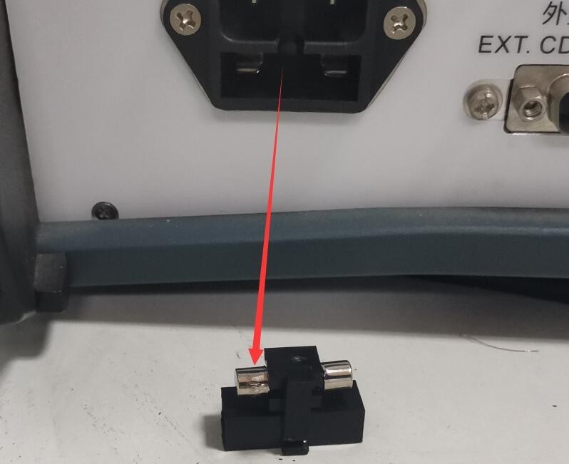
Gambar 39
Gambar di bawah ini menunjukkan lokasi varistor (MOV) di dalam catu daya yang telah difilter:
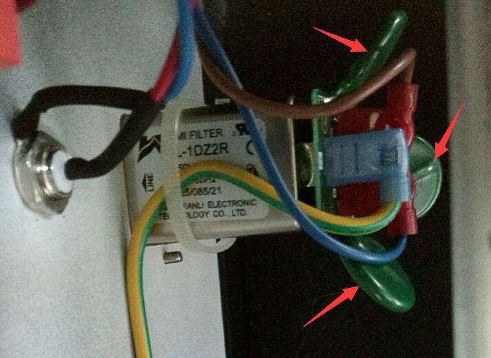
Gambar 40
7.2 Symptom: The circuit breaker trips immediately after startup
Possible causes: Short circuit in the EUT; short circuit between the EUT input and output conductors
Troubleshooting: Check whether the EUT’s input/output wires are exposed or shorted, and replace any damaged cables; check whether the EUT is shorted (measure the resistance at the EUT’s power input terminals with a multimeter); after resolving the EUT fault, try again.
7.3 Symptoms: The “(START) Start Test” button cannot be activated
Possible causes: The voltage has not been adjusted properly; the EUT has not been powered on.
Solution: Wait 3 to 5 seconds to allow the device to automatically adjust the voltage to the set value (wait until the Vr and Vd readings stabilize); click the “EUT Power” button to power on the EUT, then try again.