
 Inggris
 中文简体
中文简体 Русский
 Español
 Português
 Türkçe
 العربية
 Deutsch
 Polski
 Italiano
 Français
 한국어
한국어 ไทย
ไทย Tiếng Việt
 日本語
日本語





























Digital Torsi Meter
Pengguna manual
berlaku LISUN Model: CH338
1. Membuka Kemasan dan Mengenal Peralatan Secara Dasar
1.1 Spesifikasi Teknis Utama
| Parameter Teknis | Note |
| Rentang torsi | 0–10 N·m |
| Arah Pengukuran | Clockwise + Counterclockwise |
| Alarm Function | A maximum limit can be preset; an alarm is triggered if the test value exceeds this limit. |
| Lamp Holder Fixture | Various sockets can be configured as needed, such as E27/E26, B22d, E14/E12, G13/G5, etc. |
1.2 Membuka Kemasan dan Memeriksa Isinya
1.2.1 Membuka Kemasan dan Pemeriksaan Visual
Saat membuka kemasan perangkat, tangani dengan hati-hati untuk menghindari goresan pada casing luar dengan alat tajam. Setelah membuka kemasan, periksa terlebih dahulu bagian luar perangkat untuk memastikan tidak ada deformasi atau penyok yang terlihat, dan tombol-tombolnya tidak rusak atau longgar. Jika Anda melihat kelainan pada perangkat atau aksesorinya, jangan menyalakannya. Segera hubungi kami.
1.2.2 Unit Utama dan Aksesoris
Main Unit: 1 CH338 Digital Torsion Meter.
The standard accessories are as follows:
| Jumlah | Note |
| ① | Kabel Listrik |
| ② | Several lamp holders |
Download links for the digital user manual, software, warranty card, and other items have been sent via email. Please download them as soon as possible. If you missed the email, please feel free to contact us to receive the download links again.
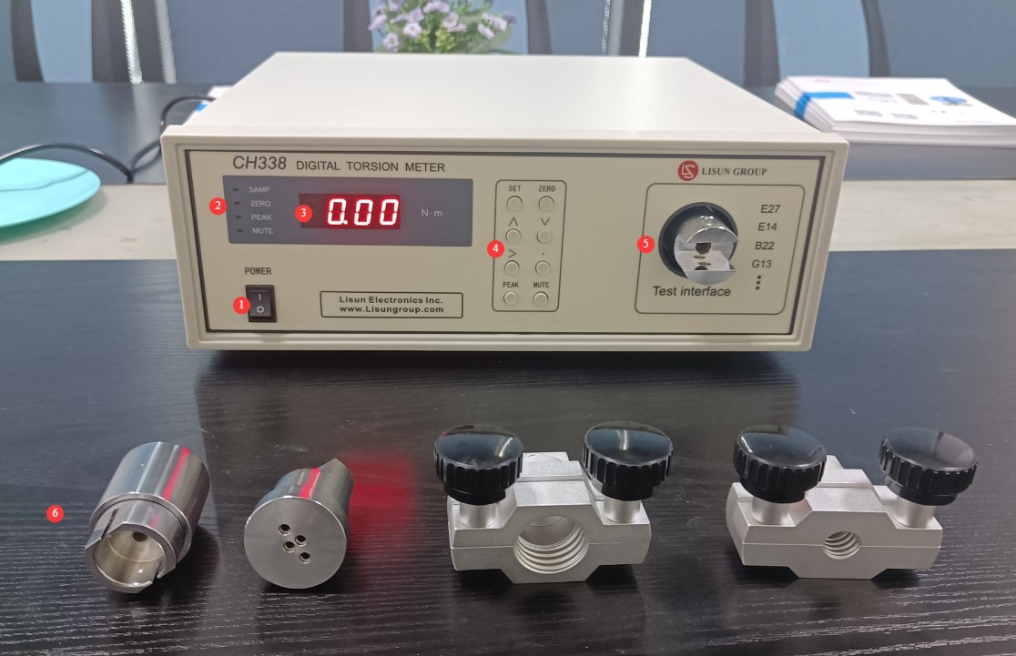
1.3 Gambaran Umum Peralatan
| Jumlah | Note |
| ① | Saklar daya |
| ② | Device status indicators. SAMP (Sampling): Flashing = measurement in progress; refreshes approximately twice per second; ZERO (Zero Calibration): Lit = zero calibration mode; PEAK (Peak): Lit = peak hold; MUTE (Mute): Lit = buzzer off |
| ③ | Torque Display Window |
| ④ | Keypad. ZERO: Zero the measurement; PEAK: Clear the peak value; SET: Enter torque upper limit setting; PEAK: Toggle between peak hold and normal measurement; ∧/∨: Increase/decrease digits; >: Move cursor to the right; •: Set decimal point; MUTE: Buzz alarm on/off switch |
| ⑤ | Torque measurement interface, connects to the device’s internal sensor |
| ⑥ | Lamp Holder Fixture |
Gambar 1
2. Tindakan Pencegahan Keamanan
2.1 Keamanan Listrik
2.1.1 Koneksi Daya
Single-phase AC 220 V ±10 V, 50/60 Hz. The power outlet must comply with safety standards and provide proper protective grounding. Ensure that all connections are secure and free of looseness.
2.1.2 Grounding Standards
The equipment must be reliably grounded, with a grounding resistance of ≤4 Ω. Do not use gas pipes, non-metallic water pipes, or the neutral wire as a substitute for the ground wire. This will help prevent electric shock, equipment malfunctions, or measurement errors caused by poor grounding.
2.2 Keselamatan Operasional
Measuring range: 0–10 N·m; maximum overload: 12 N·m (120% FS); exceeding the maximum overload may damage the sensor;
When installing fixtures or test specimens, do not tap or bump the sensor. Rotate at a constant speed during testing, and do not twist it forcefully;
When moving instruments, handle them with care to avoid violent shaking or impact, and place them securely on a stable surface;
Before inspecting or maintaining equipment, you must disconnect the main power supply and confirm that there is no residual voltage before proceeding;
Do not operate the equipment’s power switch or instrument buttons with wet hands to avoid the risk of electric shock; do not plug in or unplug the power cord while the equipment is running.
2.3 Keselamatan Lingkungan
Operating temperature: 0–40°C; Operating humidity: ≤65% RH;
The use of this instrument in explosive atmospheres or areas where flammable or explosive materials are stored is strictly prohibited to prevent safety incidents;
Keep away from oil, water, and chemicals to prevent corrosion of the sensor;
Keep away from strong electromagnetic interference and heat sources.
2.4 Lainnya
Untuk hal-hal yang tidak tercakup dalam panduan ini, harap berhati-hati atau hubungi kami.
3. Persiapan Sebelum Ujian
3.1 Pemasangan Perlengkapan
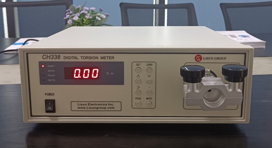
Secure the fixture to the sensor spindle using M6 hex socket screws, ensuring there is no looseness or misalignment. Do not strike the measurement interface.
Gambar 2
3.2 Equipment Warm-up
After turning on the device, let it warm up for 5 minutes to ensure stable measurements.
3.3 Instrument Zero Calibration Procedure
3.3.1 Prerequisites for Zero Calibration
The sensor is not under any torque load, the fixture is unloaded, preheating is complete, and the display is stable.
3.3.2 Standard Procedure for Zero Calibration
| petunjuk | Note |
| ① | Press the ZERO key; the display shows “ZERO,” and the ZERO indicator lights up. |
| ② | Press the ZERO key again, and the instrument will automatically zero itself. |
| ③ | The ZERO light turns off, zero calibration is complete, and the system returns to measurement mode. |
3.4 Setting the Upper Torque Limit
| petunjuk | Note |
| ① | In measurement mode, press the SET key; the window will display “SET.” |
| ② | Press the SET button again to enter upper limit editing mode. |
| ③ | Use the >, ∧, ∨, and • keys to set the target torque (e.g., 3 N·m) |
| ④ | Press the SET button to save and exit. |
In accordance with the requirements of the GB/T 14196.1-2023 standard, the torque test requirements for different lamp sockets are as follows:
| Jenis Dudukan Lampu | Initial Torque (Tested at Room Temperature) | Torque After Heating (tested after heating at the specified temperature and for the specified duration) |
| B15 | 1.15 N · m | 0.75 N · m |
| B15d | ||
| B22 | 3.0 N · m | 2.0 N · m |
| B22d | ||
| E12 | 0.8 N · m | 0.5 N · m |
| E14 | 1.15 N · m | 0.75 N · m |
| E17 | 1.5 N · m | 1.0 N · m |
| E26 | 3.0 N · m | 2.0 N · m |
| E26d | ||
| E27 |
3.5 Pengaturan Lainnya
3.5.1 Switching Between Measurement and Peak Modes
In measurement mode, the display shows the real-time torque value; if you press the PEAK button, it displays the maximum value from the current measurement; pressing the PEAK button again returns you to measurement mode.
3.5.2 Buzzer Alarm On/Off Switch
You can toggle this setting by pressing the MUTE button.
4. Prosedur Uji
4.1 Sample Installation and Securing
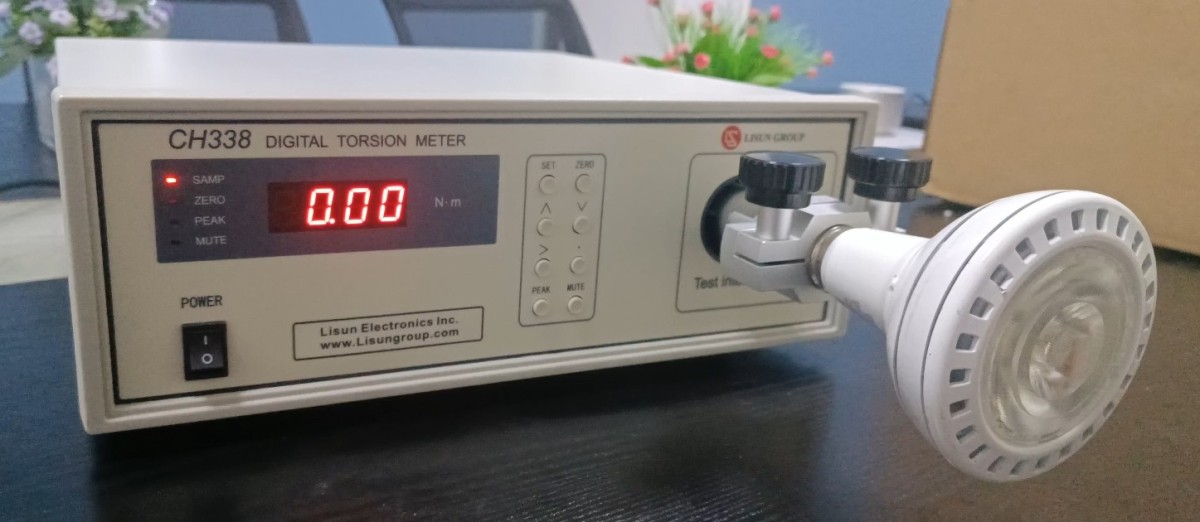
Fully insert the lamp base under test into the corresponding fixture, ensuring a snug fit with no gaps. Tighten manually to ensure there is no relative movement between the lamp base and the fixture. Do not apply excessive force to avoid deforming the lamp base.
Gambar 3
4.2 Torque Test Procedure
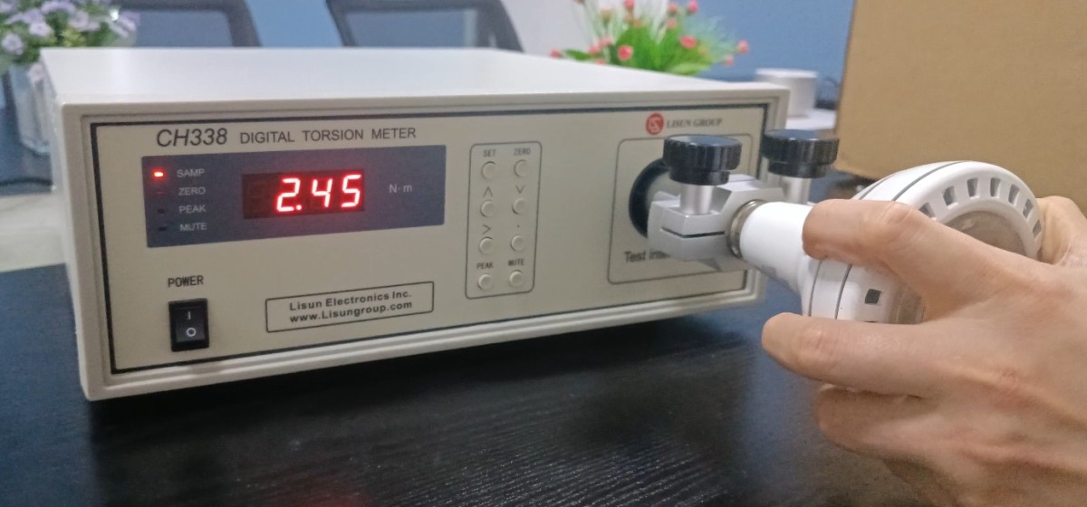
Forward: Rotate clockwise; Reverse: Rotate counterclockwise. Rotate at a constant speed without any sudden jerks.
Rotate until the instrument emits a beep (if the alarm is enabled), then stop rotating immediately; the alarm indicates that the torque has reached the set upper limit.
After rotation stops, if the system is in measurement mode, the window will display a torque value of zero; if it is in peak mode, the window will continue to display the peak torque value from the current test. Press the ZERO key to reset the peak data to zero.
Gambar 4
4.3 Interpretasi Hasil Tes
Acceptance Criteria: After testing, there must be no relative displacement between the lamp base and the glass envelope; there must be no looseness or separation.
5. Pemeliharaan dan Perawatan Peralatan Harian
5.1 Routine Equipment Maintenance
Wipe the instrument’s control panel and housing with a dry, soft cloth to remove dust and grease. Avoid using corrosive or solvent-based cleaners, such as acetone.
Regularly clean dust and oil residue from measurement interfaces and fixtures, and keep the threads in good condition.
5.2 Long-Term Storage and Maintenance (When Not in Use for More Than 1 Month)
Turn off the instrument, unplug all cables, and cover the instrument with a dust-proof cloth to prevent dust buildup;
Select a dry, well-ventilated area free of corrosive gases, with an ambient temperature of -20 to 50 °C and a relative humidity of <75% RH;
Organize accessories such as power cords and clamps, pack them separately, and store them to prevent crushing;
Power on the instrument once a month for 30 minutes to ensure that its electronic components are functioning properly.
6 Troubleshooting and Resolving Common Problems
| Gejala Kesalahan | Kemungkinan penyebab | Prosedur |
| Tidak dapat menyala | Kabel daya tidak terpasang dengan benar; sekring putus. | Plug the power cord back in; check the fuse, and if it is blown, replace it with a 0.5A fuse of the same type. |
| No display appears on the screen after powering on | Loose internal wiring, display malfunction | Please disassemble the device following our instructions and check the internal wiring connections; contact us to have the display replaced. |
| Abnormal torque data | Missing calibration data or equipment that has fallen into disrepair | Please contact us for torque calibration instructions. |