
 Inggris
 中文简体
中文简体 Русский
 Español
 Português
 Türkçe
 العربية
 Deutsch
 Polski
 Italiano
 Français
 한국어
한국어 ไทย
ไทย Tiếng Việt
 日本語
日本語





























Menyerap Clamp
Pengguna manual
berlaku LISUN Model: AB-CLP
1. Pemahaman Dasar tentang Peralatan
1.1 Ikhtisar Produk
1.1.1 Parameter Utama
| Parameter Teknis | indikator | Catatan |
| Rentang frekuensi | 30 MHz sampai 1000 MHz | Rated Operating Frequency Band |
| Output Impedance | 50 Ω | Matching Coaxial System |
| Allowed cable diameter for testing | ≤20 mm | Exceeding the specifications may damage the equipment. |
| Konektor Sinyal | Tipe N | Port Output |
| Absorption Clamp Factor CF | -4 dB to 4 dB | That is, the correction factor K varies with frequency |
| Decoupling Factor (DF) | ≥21 dB | Ensure isolation between the test side and the power supply side |
| Faktor Dekopling DR | ≥30 dB | Decoupling Capability of Coaxial Cable Shielding |
| Ukuran | 640 mm (P) × 109 mm (L) × 100 mm (T) | |
| Berat | 5 kg | |
1.1.2 Skenario Aplikasi
The AB-CLP Absorbing Clamp (ACA) is a specialized device used for disturbance power testing in the field of electromagnetic compatibility (EMC) and serves as an alternative measurement device for radiated emission testing. By coupling and extracting common-mode disturbance power from the cable under test, it indirectly evaluates the device’s radiated emission levels. Since it does not require a large anechoic chamber, it can significantly reduce testing costs and shorten testing cycles, and is widely used in product R& D debugging and pre-compliance testing scenarios.
1.2 Scope of Application and Basis for Standards
1.2.1 Equipment and Method Standards
The performance of this system’s equipment and the test methods fully comply with the following international and national standards:
Equipment Specifications: CISPR 16-1-3, GB/T 6113.103 (Specifications for Equipment for the Measurement of Radio Disturbance and Immunity—Part 3: Equipment for the Measurement of Disturbance Power)
Test Method Standards: CISPR 16-2-2, GB/T 6113.202 (Methods for Measuring Radio Disturbance and Immunity—Part 2: Measurement of Disturbance Power)
1.2.2 Applicable Products and Test Frequencies
The absorption clamp method is primarily used to evaluate electromagnetic interference radiated by equipment through power and signal lines. The mandatory test frequency bands vary depending on the product standard:
The 30 MHz to 300 MHz frequency range (which provides full coverage when used with the EMI-9KB)
is the mandatory compliance testing range for the vast majority of products. The corresponding product standards include:
CISPR 14-1 / GB 4343.1: Electromagnetic Compatibility—Emission Requirements for Household Appliances, Power Tools, and Similar Equipment; CISPR 15 / GB 17743: Radio Disturbance Characteristics of Electrical Lighting and Similar Equipment.
300 MHz to 1000 MHz (requires use with the EMI-9KC penerima)
The AB-CLP Absorbing Clamp has a rated frequency range of 30 MHz to 1000 MHz, while the EMI-9KC receiver has an upper frequency limit of 1000 MHz.
When testing products such as audio-video receivers and multimedia devices (in accordance with standards such as CISPR 13 and CISPR 32), the standards require evaluation of disturbance power across the entire 30 MHz to 1000 MHz frequency band.
1.3 Verifikasi Konfigurasi Peralatan
1.3.1 Membongkar
When unpacking the device, handle it gently to avoid scratching the exterior with sharp tools. After unpacking, first inspect the exterior of the device to ensure there is no visible deformation or dents, and that the buttons are not damaged or loose. If you notice any abnormalities with the device or its accessories, please contact us immediately.
1.3.2 Unit Utama dan Aksesoris
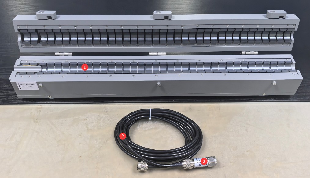
Lihat Gambar 1-1.
| Jumlah | Note |
| ① | AB-CLP Menyerap Clamp |
| ② | Kawat koaksial |
| ③ | Attenuator Koaksial 6 dB |
Gambar-1 1
1.3.3 Mengunduh Dokumen Elektronik
Links to the electronic user manual, warranty card, calibration certificate, and other documents have been sent via email. If you missed the email, please contact us to receive the links again.
2. Tindakan Pencegahan Keamanan
2.1 Keamanan Listrik
The device under test and the receiver must each be connected to the power grid via an Isolation Transformer that meets the appropriate specifications. Direct connection to the mains power supply is strictly prohibited to prevent power surges and the risk of electric shock.
A separate and reliable grounding system must be installed; the lower the grounding resistance, the more accurate the test results will be. Sharing a grounding electrode with high-power electrical equipment is strictly prohibited, and the grounding terminals of all equipment must be securely connected to the grounding electrode.
Do not use the equipment if the power connections are loose or the cable sheath is damaged; during thunderstorms, disconnect all equipment from the power source and ground connections to prevent damage from lightning strikes.
The receiver’s RF input port is a sensitive RF interface; do not connect high-voltage or high-level signals directly to it, as this may damage the internal circuitry.
2.2 Keselamatan Operasional
Strictly follow the sequence: “Turn on the peripherals first, then the computer; turn off the computer first, then the peripherals.”
Before powering on or off the device under test, you must first disconnect the coaxial cable from the front end of the receiver to prevent switching transients from damaging the receiver’s internal circuitry; under no circumstances should you plug in or unplug the coaxial cable during testing.
When opening and closing the Absorbing Clamps, operate them smoothly to avoid pinching your hands; do not insert cables or hard metal objects with a diameter greater than 20 mm into the jaws to prevent the internal ferrite cores from cracking.
During testing, move the absorption clamp by gently pushing and pulling it to avoid violent impacts with the slide rail, thereby preventing displacement of the internal components that could affect test accuracy.
Unless authorized by the manufacturer, do not disassemble the casing of the absorption clamp or the receiver unit; otherwise, your warranty will be void.
2.3 Keselamatan Lingkungan
The equipment operating environment temperature is 5–35°C, with a relative humidity of ≤80% and no condensation; flammable, explosive, or corrosive materials must not be stored in the test area.
It is recommended that formal testing be conducted in an electromagnetically shielded room; for preliminary testing, select a separate room located far from sources of strong electromagnetic interference—such as variable-frequency drives, arc welders, high-power chargers, and wireless transmitting equipment—to minimize the impact of environmental background noise.
The test area must be at least 0.8 m away from walls and other large conductive objects to prevent electromagnetic wave reflections from affecting the test results.
3. Introduction to Auxiliary Equipment and System Wiring
3.1 EMI-9KB Penerima
3.1.1 Panel Depan
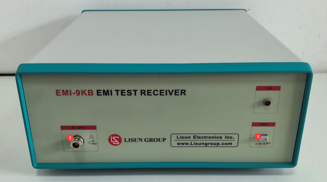
Lihat Gambar 3-1.
| Jumlah | Note |
| ① | Saklar daya |
| ② | RF input port, connected to the AB-CLP using a coaxial attenuator and coaxial cable |
Gambar-3 1
3.1.2 Panel Belakang
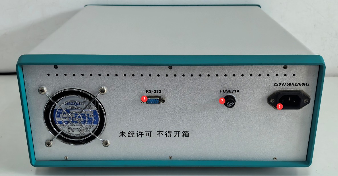
Lihat Gambar 3-2.
| Jumlah | Note |
| ① | Power cord jack, connected to an Isolation Transformer |
| ② | Sekering |
| ③ | RS-232 communication port: Connect to a computer using an RS-232 cable. If the computer does not have an RS-232 port, you can use the standard RS-232-to-USB adapter cable to connect to the computer. Note: Do not use non-standard cables or adapters, as this may cause communication errors. |
Gambar-3 2
3.2 Test System Wiring Procedure
Please complete the system wiring in the following order to ensure reliable connections.
| Instruksi Pengkabelan | Note |
| ① Power Supply Circuit Wiring | Connect Isolation Transformer 1 to the mains power supply; use its output to connect the power supply circuit for the device under test. Connect Isolation Transformer 2 to the mains power supply; connect its output to the EMI-9KB receiver and the computer. |
| ② Wiring the Absorber Clamp to the Receiver | Screw the 6 dB coaxial attenuator onto the N-type output port of the AB-CLP Absorbing Clamp; connect one end of the coaxial cable to the 6 dB attenuator and the other end to the RF input port of the EMI-9KB penerima. |
| ③ Communication Wiring | Gunakan sebuah RS232 cable to connect one end to the RS232 port on the back panel of the receiver and the other end to the computer, either directly or via an RS232-to-USB adapter. |
| ④ Grounding Connection | Reliably connect the receiver’s ground terminal and the metal reference ground plate used for testing to a separate ground electrode using a copper ground wire. |
4. EMI-9KB Software Installation and Overview
4.1 Instalasi Perangkat Lunak dan Driver
4.1.1 Persyaratan Operasi Sistem
Sistem Operasi: Windows 7 / Windows 8 / Windows 10 / Windows 11; Windows 10 direkomendasikan;
Hardware Requirements: Pentium or higher processor, ≥2 GB of RAM, ≥1 GB of free hard drive space, and at least one available USB port;
Resolusi layar: 1024×768 atau lebih tinggi direkomendasikan.
Instalasi 4.1.2
Lihat Gambar 4-1.
| Jumlah | Note |
| ① | EMI-9KB Perangkat Lunak PC Penerima—Klik dua kali untuk menginstal |
| ② | RS-232-to-USB Adapter Driver: If you are using an RS-232-to-USB adapter, you must install this driver. |

Gambar-4 1
4.1.3 Pengaturan Port Komunikasi
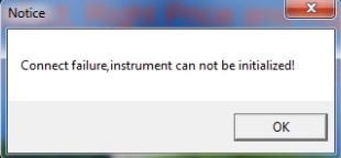
Saat Anda membuka perangkat lunak untuk pertama kalinya, Anda mungkin melihat pesan kesalahan komunikasi, seperti yang ditunjukkan pada Gambar 4-2.
Gambar-4 2
Klik OK untuk membuka antarmuka awal perangkat lunak, lalu klik Uji > Pengaturan Port, seperti yang ditunjukkan pada Gambar 4-3.
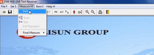
Gambar-4 3
Cukup pilih nomor port komunikasi yang benar secara manual, seperti yang ditunjukkan pada Gambar 4-4.
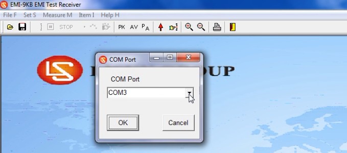
Gambar-4 4
As shown in Figures 4 and 5, you can go to “My Computer” > “Properties” > “Device Manager” to verify the communication port used by the device.
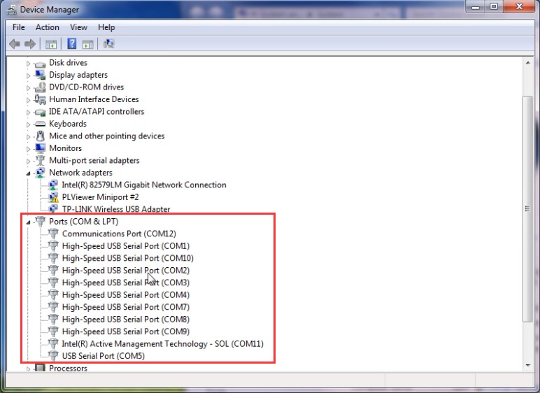
Gambar 4–5
The next time you open the software, it will open directly to the initial interface. Note: If the communication port changes, you will need to reselect the correct communication port.
4.2 Introduction to Software Interface Features
4.2.1 Menu File
4.2.1.1 Daftar Dropdown
Lihat Gambar 4–6.
| Jumlah | Note |
| ① | Buka file EMC |
| ② | Simpan hasil pengujian sebagai file emc. Catatan: file emc hanya dapat dibuka menggunakan LISUN EMI-9KB perangkat lunak. |
| ③ | Pengaturan Laporan Pengujian |
| ④ | Print a report that includes data from the final test points |
| ⑤ | Cetak laporan yang mencakup data tentang tempat-tempat menarik. |
| ⑥ | Keluar dari Perangkat Lunak |
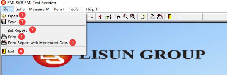
Gambar 4–6
4.2.1.2 Report Option Information
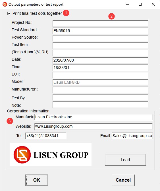
Saat menyimpan atau mencetak laporan pengujian, layar berikut akan muncul terlebih dahulu, seperti yang ditunjukkan pada Gambar 4-7.
| Jumlah | Note |
| ① | Simpan/Cetak Data Titik Inspeksi Akhir/Titik Fokus? |
| ② | Isilah informasi terkait tes. |
| ③ | Fill in the Laboratory Information |
Gambar 4-7
4.2.2 Menu Pengaturan
4.2.2.1 Daftar Dropdown
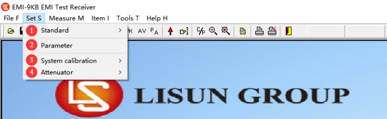
Lihat Gambar 4–8.
| Jumlah | Note |
| ① | Test Standards: Select, Add, Edit, or Delete Standards |
| ② | Parameter pengujian: Tidak perlu perubahan; cukup gunakan pengaturan default. |
| ③ | System Calibration: Used by professional engineers when commissioning the equipment; this function is not required during normal operation. |
| ④ | Peredam getaran: Pilih berdasarkan kondisi aktual. |
Gambar-4 8
4.2.2.2 Opsi Standar Tes
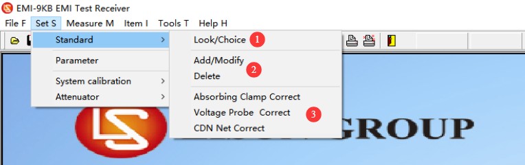
Lihat Gambar 4–9.
| Jumlah | Note |
| ① | Kriteria Seleksi: Anda hanya dapat memilih kriteria yang telah ditambahkan sebelumnya; Anda tidak dapat mengubah parameternya. |
| ② | Tambahkan, ubah, atau hapus standar. Catatan: Harap berhati-hati; semua standar dan kurva batas ditambahkan sesuai dengan standar yang ada. Jika Anda memiliki data standar lain yang tidak termasuk dalam perangkat lunak kami, silakan kirimkan standar yang relevan kepada kami, dan kami akan menambahkannya untuk Anda. |
| ③ | Absorbing Clamps, Voltage Probes, CDN network correction. Note: For use only by LISUN insinyur profesional saat melakukan debugging perangkat lunak. |
Gambar-4 9
4.2.2.3 Opsi Attenuator
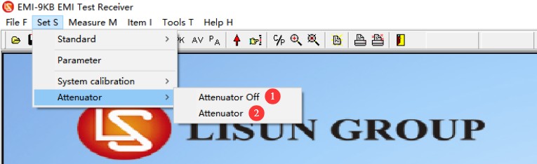
Lihat Gambar 4-10.
| Jumlah | Note |
| ① | Jangan gunakan attenuator. |
| ② | Saat menggunakan attenuator, harap pilih dan masukkan parameter atenuasi yang benar di dalam perangkat lunak. |
Gambar-4 10
Note: When connecting the EMI-9KB ke AB-CLP, a 6 dB attenuator must also be connected; please set the correct attenuator parameters before use.
4.2.3 Menu Tes
Lihat Gambar 4-11.
| Jumlah | Note |
| ① | Untuk pengaturan port komunikasi, lihat 4.1.3 |
| ② | Pindai: Lakukan uji pemindaian sesuai dengan kriteria dan pengaturan parameter yang dipilih pada saat itu. |
| ③ | Tes Setitik: Jika Anda hanya ingin melihat data untuk titik frekuensi tertentu, klik di sini untuk memasukkan frekuensi secara manual dan menjalankan tes. |
| ④ | Tes Akhir: Setelah tes pemindaian selesai, jika Anda ingin menguji data spesifik untuk titik-titik tertentu lagi, Anda dapat melakukan tes akhir. |
| ⑤ | Pengujian Akhir Otomatis: Perangkat lunak secara otomatis memilih titik frekuensi representatif berdasarkan hasil pengujian untuk pengujian akhir. |
| ⑥ | Manual Final Test: Users manually add the frequency points to be tested based on their needs. |
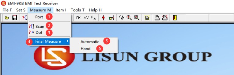
Gambar-4 11
4.2.4 Menu Tampilan
Lihat Gambar 4-12.
| Jumlah | Note |
| ① | Grafik tersebut menunjukkan garis PK dan AV default. |
| ② | Tambahkan titik pemantauan; fitur ini berfungsi sama seperti pada pengujian akhir di versi 4.2.3, dan Anda dapat mengatur titik frekuensi secara manual. |
| ③ | Tampilkan data yang berada di luar kurva batas. |
| ④ | Tampilkan data untuk titik uji akhir. |
| ⑤ | Setelah melakukan dua tes pemindaian berturut-turut, Anda dapat mengklik untuk membandingkan hasil dari kedua tes tersebut. |
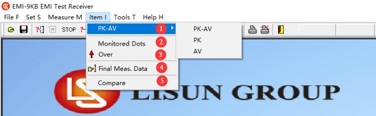
Gambar-4 12
4.2.5 Introduction to Navigation Bar Shortcut Keys
Lihat Gambar 4-13.
| Jumlah | Note |
| ① | Buka file EMC |
| ② | Simpan sebagai file emc |
| ③ | Tes Pemindaian |
| ④ | Pengujian Jeda |
| ⑤ | Hentikan Pengujian |
| ⑥ | Spot Measurement |
| ⑦ | Pengujian Akhir Otomatis |
| ⑧ | Pengujian Akhir Manual |
| ⑨ | Kurva Tampilan: PK, AV, PK+AV |
| ⑩ | Tampilkan data yang berada di luar kurva batas. |
| ⑪ | Tampilkan data untuk titik pemeriksaan akhir. |
| 1 | Tampilkan atau sembunyikan titik data yang tumpang tindih (menyembunyikan titik data yang tumpang tindih membuat kurva lebih jelas) |
| ⑬ | Perbesar/Perkecil: Anda dapat memperbesar kurva untuk tampilan yang lebih mudah. Setelah mengklik, gulir roda tombol tengah mouse di area tampilan kurva untuk memperbesar atau memperkecil. |
| ⑭ | Pengaturan Laporan Pengujian |
| 3 | Cetak laporan yang mencakup data titik uji akhir. |
| 5 | Cetak laporan yang mencakup data tentang tempat-tempat menarik. |
| ⑰ | Keluar dari Perangkat Lunak |
| ⑱ | Menampilkan parameter modul internal perangkat; ditujukan semata-mata untuk digunakan oleh insinyur profesional selama proses debugging. |
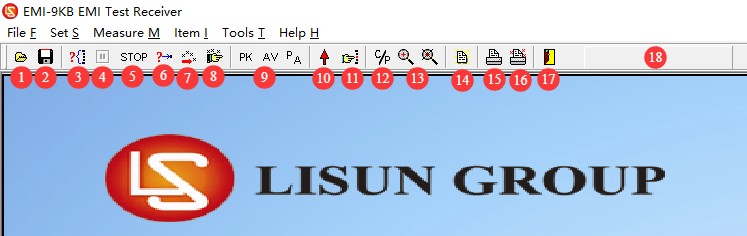
Gambar-4 13
5. Pre-Test Preparation and System Setup
5.1 Persyaratan Lingkungan Pengujian
Shielded Room Solution (Compliance Testing): Formal conformity assessment testing must be conducted in a standard-compliant electromagnetic shielded room that completely isolates the test equipment from external interference, ensuring the authority of the test results.
Standard Room Specifications (Preliminary Testing): For R& D preliminary testing, a dedicated room with an area of at least 15 square meters and free of other devices that generate strong electromagnetic interference should be used. Priority should be given to rooms on the first floor to facilitate grounding and reduce grounding resistance.
Sufficient space must be reserved in the test area to accommodate the length of the slide rails and the required spacing between equipment.
5.2 Requirements for Standard Test Setups
The test setup strictly complies with the requirements of the CISPR 16-2-2 / GB/T 6113.202 standard and is divided into two configurations—desktop and floor-standing—based on the type of equipment under test.
5.2.1 Layout of Benchtop Equipment Under Test (EUT)
See Figure 5-1 (taken from CISPR 16-2-2, Figure 8).
Place the insulation test bench above the ground reference plane, with the bench top at a height of 0.8 m; place the equipment under test securely on the test bench, with the rear of the equipment 0.4 m away from the metal wall or ground reference plane.
Place an insulated slide rail that is 0.8 m high horizontally; the rail must be at least 6 m long and located on the same horizontal plane as the equipment under test.
The lead under test (LUT) must be straightened and placed horizontally, with one end connected to the device under test and the other end extending along the slide rail and hanging naturally to the ground, where it is connected to a power source; The total length of the lead under test shall be no less than 7.5 m (including a 6 m section on the slide rail, a 1 m hanging section, and a 0.5 m allowance). If the length of the equipment’s original power cord is insufficient, it must be extended using a replacement cord of the same type and construction.
Open the Absorbing Clamp, insert the wire to be tested into the center hole of the Clamp, close the Clamp, and secure the latch; place the Absorbing Clamp on the slide rail so that it can slide freely along the rail.
The initial distance between the slide rail reference point (SRP) and the clamp reference point (CRP) is set to 10 ± 1 cm. This distance has a significant impact on the test results and must be strictly controlled.
Connect an attenuator, coaxial cable, and the EMI-9KB receiver to the output of the absorption clamp as specified in Chapter 3. Place the receiver on the outer side of the end of the slide rail to avoid interfering with the test area.
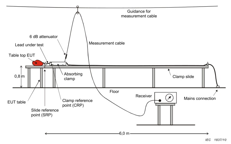
Gambar-5 1
5.2.2 Floor-Standing Equipment Under Test (EUT) Setup
See Figure 5-2 (taken from CISPR 16-2-2, Figure 9).
Place a metal grounding reference plate measuring at least 2 m × 2 m on the floor. Place an insulating mat 0.1 m high on top of the metal plate, and carefully place the device under test on the insulating mat.
The insulated rail remains at a height of 0.8 m and is positioned horizontally next to the equipment under test; the rest of the wiring layout, absorption clamp installation, and spacing requirements are the same as those for the benchtop unit.
All surfaces of the device under test must be at least 50 cm from the edge of any metal plate and at least 80 cm from any conductive objects in the vicinity.
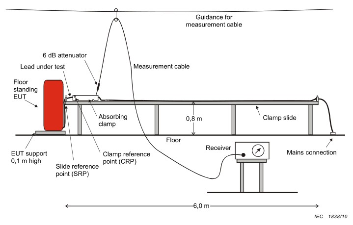
Gambar-5 2
6. Procedure for Interference Power Testing
6.1 Powering On and Warm-Up
First, turn on the Isolation Transformer, then turn on the EMI-9KB receiver, and finally turn on the computer and launch the test software;
After turning on the receiver, let it warm up for 10 minutes; wait until the internal circuitry has stabilized before beginning the test;
Turn on the power to the device under test to bring it into normal operating mode, and allow it to warm up to a stable operating state in accordance with the standard requirements (typically 15 to 30 minutes).
6.2 Konfirmasi Parameter Uji
6.2.1 Pemilihan Standar
Refer to Section 4.2.2.2. Go to the standard selection menu and choose the standard labeled “Power”; this is the standard for Absorbing Clamps. See Figure 6-1.
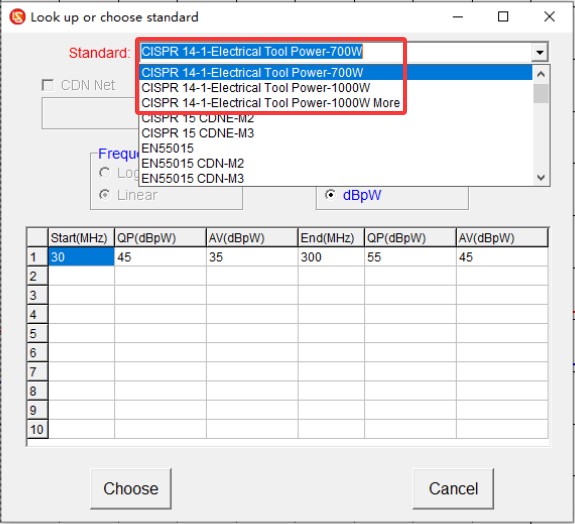
Gambar-6 1
6.2.2 Pengaturan Attenuator
Refer to Section 4.2.2.3 and select a 6 dB attenuator, as shown in Figure 6-2.
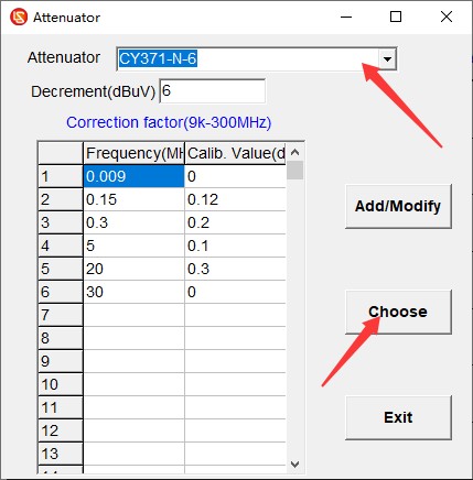
Gambar-6 2
6.4 Scan Test
Click “Scan Test,” wait for the scan to complete, and if any issues arise, click “Stop Test,” make the necessary adjustments, and then restart the test. The scan is complete; see Figure 6-3.
Garis merah: Garis batas quasi-peak (QP);
Garis biru: Garis batas rata-rata (AV);
Kurva hijau: Kurva uji puncak (PK);
Kurva biru: Kurva uji rata-rata (AV).
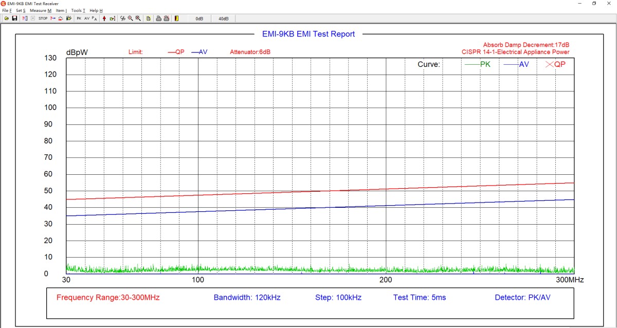
Gambar-6 3
6.5 Final Exam
If the average values (AV) of the test results are all below the limit curve, and the peak values (PK) are all below the quasi-peak (QP) limit curve, then the EUT meets the standard requirements, because the actual quasi-peak (QP) value measured during testing will not exceed the peak (PK) value. If the tested peak value (PK) exceeds the quasi-peak (QP) limit curve, the EUT does not necessarily fail to meet the standard requirements; a final test must be conducted.
6.5.1 Pengujian Akhir Otomatis
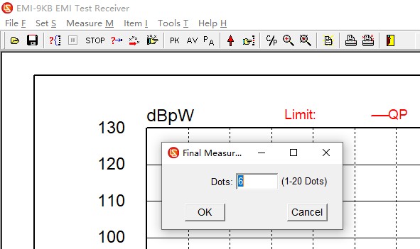
Masukkan jumlah titik frekuensi yang akan diuji, dan perangkat lunak akan secara otomatis memilih titik frekuensi berdasarkan kurva uji untuk melakukan pengujian akhir, seperti yang ditunjukkan pada Gambar 6-4.
Gambar-6 4
6.5.2 Pengujian Akhir Manual
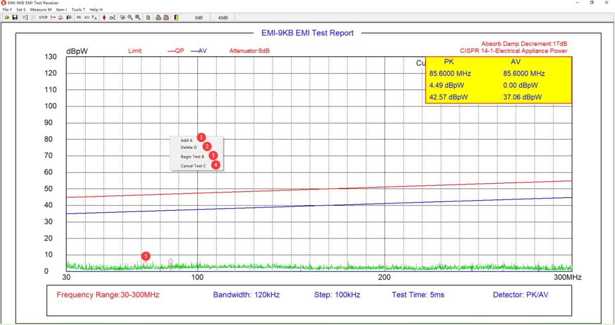
In the software test curve area, right-click on the point where you want to perform the final test, as shown in Figure 6-5.
| Jumlah | Note |
| ① | Tambahkan Endpoint |
| ② | Hapus Titik Akhir |
| ③ | Setelah menambahkan semua poin pengujian akhir yang diperlukan, klik “Mulai Pengujian Akhir.” |
| ④ | Jika Anda tidak lagi ingin berpartisipasi dalam ujian akhir, klik “Batalkan Ujian Akhir.” |
| ⑤ | Berlian biru menunjukkan lokasi titik uji akhir yang ditambahkan. |
Gambar-6 5
6.5.3 Menambahkan Tempat Menarik
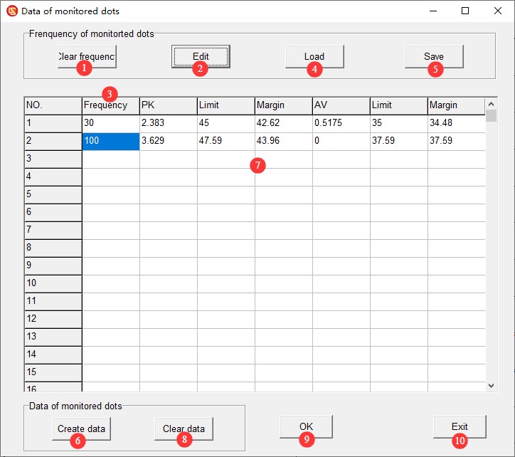
Lihat Gambar 6-6.
| Jumlah | Note |
| ① | Klik untuk menghapus semua titik frekuensi dan data dari layar saat ini. |
| ② | Tap to edit the frequency point status; tap again to exit the frequency point editing mode. |
| ③ | Titik frekuensi untuk diedit; Anda dapat memasukkan setiap titik frekuensi secara manual. |
| ④ | Anda dapat langsung memuat file titik frekuensi yang telah Anda edit sebelumnya. |
| ⑤ | Anda dapat menyimpan berkas data titik frekuensi yang sedang Anda edit agar dapat diakses langsung selama pengujian akhir. |
| ⑥ | Klik “Buat Data” untuk langsung membaca data uji untuk titik frekuensi yang sesuai dari laporan uji saat ini. |
| ⑦ | Bacalah data uji untuk titik frekuensi yang sesuai dari laporan uji saat ini. |
| ⑧ | Klik “Hapus Data” untuk menghapus data yang telah diambil. |
| ⑨ | Klik OK untuk menyimpan data titik fokus saat ini ke laporan pengujian. |
| ⑩ | Klik KELUAR untuk keluar segera tanpa menyimpan data titik fokus layar saat ini. |
Gambar-6 6
6.5.4 Interpretasi Data Uji Akhir
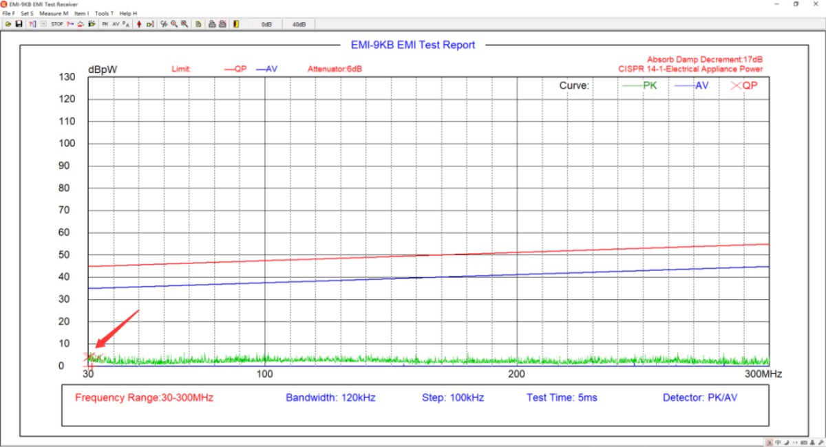
See Figures 6–7. The red X marks the quasi-peak (QP) values from the final test. If all quasi-peak (QP) values from the final test are below the quasi-peak (QP) limit curve, the EUT meets the standard requirements. Otherwise, it does not meet the standard requirements.
Gambar 6–7
6.6 Save and Print the Test Report
Lihat Bagian 4.2.1 untuk menyimpan atau mencetak laporan pengujian.
6.7 Procedure for Shutting Down the Machine at the End of a Test
Ensure the equipment is in the “test stop” state → Disconnect the coaxial cable on the EMI-9KB receiver side → Turn off the EUT’s power → Turn off the receiver and the computer → Turn off the Isolation Transformer.
7. Pemeliharaan dan Perawatan Peralatan Harian
7.1 Perawatan Rutin
7.1.1 Absorbing Clamps
After each use, wipe the surface of the pliers with a dry, soft cloth to remove dust and stains; Do not use highly corrosive solvents such as gasoline, acetone, or thinners for cleaning. To remove stubborn stains, use a lint-free cloth dipped in a small amount of anhydrous ethanol to wipe the area quickly, then dry it immediately.
Check the latch and hinge of the pliers monthly to ensure they open and close smoothly; you may apply a small amount of silicone grease for lubrication. Inspect the N-type output connector, remove any oxidation, and cover it with a protective cap when not in use to prevent dust from entering.
Handle the equipment with care; do not drop or subject it to impact, to prevent the internal ferrite cores from shattering. Do not use the pliers to grip hard objects or apply excessive force when opening or closing them.
Do not disassemble the clamp body on your own. The internal magnetic ring and structural alignment have been calibrated before shipment; disassembly will result in a loss of testing accuracy.
7.1.2 Coaxial Cables and Attenuators
Avoid bending coaxial cables sharply, stepping on them, or subjecting them to pressure from heavy objects. When storing them, coil them loosely to prevent the internal conductors from breaking.
Tangani aksesori presisi seperti attenuator dan konektor dengan hati-hati untuk mencegah kerusakan internal akibat terjatuh.
7.2 Spesifikasi Penyimpanan
7.2.1 Persyaratan Lingkungan Penyimpanan
Suhu: 5°C hingga 35°C; kelembapan relatif: ≤65% RH; lingkungan kering, bebas debu, dan bebas dari gas korosif.
7.2.2 Operasi Penyimpanan Jangka Panjang
Turn off the power and unplug all cables; clean the equipment and wrap it in dust-proof film.
7.3 Persyaratan Interval Kalibrasi
Untuk memastikan akurasi pengukuran dan keandalan operasional peralatan, disarankan agar peralatan tersebut secara berkala dikirim ke laboratorium metrologi pihak ketiga yang berkualifikasi untuk kalibrasi. Interval kalibrasi yang disarankan adalah 12 bulan. Pengguna dapat menentukan interval kalibrasi spesifik berdasarkan frekuensi penggunaan, kondisi lingkungan, dan persyaratan sistem mutu.
8. Pemecahan Masalah dan Penyelesaian Masalah Umum
8.1 Absorbing Clamps
| Gejala Kesalahan | Prosedur |
| The suction forceps do not open and close smoothly, and the latch does not secure tightly | Clean the pivot shaft and apply a small amount of silicone grease for lubrication; remove any foreign objects from inside the jaws and ensure the magnetic ring is undamaged; verify that the diameter of the cable being tested is ≤20 mm, and replace it with a suitable cable. |
8.2 EMI-9KB Penerima
| Gejala Kesalahan | Prosedur |
| Various error messages appear while using the software, such as “The software cannot be opened” or “An error occurred during scanning.” | Pastikan Anda masuk ke komputer menggunakan akun administrator, dan pastikan perangkat lunak tersebut berjalan dengan hak akses administrator. |
| The software worked normally during the scan test, but crashed during the final test. | The final test has stricter communication requirements than the scan test. Please ensure that you are using only our original communication cable and no other communication cables or extension cords; please ensure that you are using the communication port on the back of the desktop computer (USB ports on laptops and those on the front of desktop computers typically do not provide sufficient power, which can affect communication); if that still does not work, please try adding an RS232 port to your computer and use only an RS232 cable for communication—do not use an RS232-to-USB adapter. |
| Hasil tes umumnya lebih rendah atau lebih tinggi dari yang diharapkan. | Harap verifikasi bahwa pengaturan attenuator perangkat lunak sesuai dengan kondisi sebenarnya. |
| Hasil pengujian selalu mendekati kebisingan latar belakang, dan penerima EMI tidak dapat mendeteksi sinyal apa pun. | Periksa sambungan kabel koaksial; ganti kabel koaksial dan coba lagi. |
| Tingkat kebisingan latar belakang yang terlalu tinggi dan fluktuasi yang signifikan pada data uji. | Verify that all equipment in the system uses Isolation Transformers; optimize the grounding system to reduce ground resistance; turn off other electrical equipment in the laboratory or conduct testing inside a shielded room. |